Table of Contents
Advertisement
Quick Links
Trademarks
FOXWELL is trademark of Shenzhen Foxwell Technology Co., Ltd.
All other marks are trademarks or registered trademarks of their respective
holders.
Copyright Information
©2020 Shenzhen Foxwell Technology Co., Ltd.
All rights reserved.
Disclaimer
The information, specifications and illustrations in this manual are based on the
latest information available at the time of printing.
Foxwell reserves the right to make changes at any time without notice.
Visit our website at
www.foxwelltech.us
For Technical Assistance, send us email at
support@foxwelltech.com
1
Windows Diagnostic Platform GT90 Max User's Manual V1.01
Advertisement
Table of Contents

Related Manuals for Foxwell GT90Max


Summary of Contents for Foxwell GT90Max
- Page 1 Disclaimer The information, specifications and illustrations in this manual are based on the latest information available at the time of printing. Foxwell reserves the right to make changes at any time without notice. Visit our website at www.foxwelltech.us For Technical Assistance, send us email at support@foxwelltech.com...
-
Page 2: One-Year Limited Warranty
FOXWELL. 3 The customer shall bear the cost of shipping the product to FOXWELL. And FOXWELL shall bear the cost of shipping the product back to the customer after the completion of service under this limited warranty. - Page 3 The customer will be billed for any parts or labor charges not covered by this limited warranty. d) FOXWELL will repair the Product under the limited warranty within 30 days after receipt of the product. If FOXWELL cannot perform repairs covered...
- Page 4 consequential damages, so certain of the above limitations or exclusions may not apply to you (the Consumer). This limited warranty gives the Consumer specific legal rights and the Consumer may also have other rights which vary from state to state. Windows Diagnostic Platform GT90 Max User's Manual V1.01...
-
Page 5: Safety Information
Safety Information For your own safety and the safety of others, and to prevent damage to the equipment and vehicles, read this manual thoroughly before operating your tool. The safety messages presented below and throughout this user’s manual are reminders to the operator to exercise extreme care when using this device. - Page 6 ● Fuel, oil vapors, hot steam, hot toxic exhaust gases, acid, refrigerant and other debris produced by a malfunction engine can cause serious injury or death. Do not use the tool in areas where explosive vapor may collect, such as in below-ground pits, confined areas, or areas that are less than 18 inches (45 cm) above the floor.
-
Page 7: Table Of Contents
Table of Contents ONE-YEAR LIMITED WARRANTY ..................... 2 SAFETY INFORMATION ........................5 SAFETY MESSAGE CONVENTIONS USED ..................5 IMPORTANT SAFETY INSTRUCTIONS ..................... 5 1 USING THIS MANUAL ........................10 1.1 B ..........................10 1.2 S ......................... 10 YMBOLS AND CONS 1.2.1 Solid Spot ......................... 10 1.2.2 Arrow Icon ........................ - Page 8 5.1 C ....................29 ONTROL ODULE ELECTION 5.1.1 Quick Scan ........................29 5.1.2 Control Modules ....................... 31 5.2 D ......................32 IAGNOSTIC PERATIONS 5.2.1 Read Codes ........................33 5.2.2 Clear Codes ........................35 5.2.3 Live Data .......................... 36 5.2.4 ECU Information ....................... 38 5.2.5 Active Tests ........................39 5.2.6 Special Functions ......................
- Page 9 9 REGISTRATION AND UPDATE ..................... 58 9.1 R ........................... 58 EGISTRATION 9.1.1 Register with Built-in Update Client .................. 58 9.1.2 Register through Website ....................61 9.2 U .............................62 PDATE 10 SETTINGS ............................ 63 10.1 C .......................... 63 HANGE 10.2 L ..........................64 ANGUAGE 10.3 P...
-
Page 10: Using This Manual
1 Using This Manual We provide tool usage instructions in this manual. Below are the conventions we used in the manual. 1.1 Bold Text Bold text is used to highlight selectable items such as buttons and menu options. Example: Select Diagnostic from home screen of the GT90 Max application. 1.2 Symbols and Icons 1.2.1 Solid Spot Operation tips and lists that apply to specific tool are introduced by a solid... -
Page 11: Introduction
IMPORTANT indicates a situation, which if not avoided, may result in damage to the test equipment or vehicle. Example: IMPORTANT Do not soak scanner as water might find its way into the scanner. 2 Introduction The latest Windows tablet scanner GT90 Max delivers faster and smarter diagnosis for workshops and technicians. - Page 12 2 Front-Facing Camera 3 Power Indicator - indicates the power status of the scanner. Figure 2-2 Back View 4 Rear-Facing Camera - takes pictures of VIN number, faulty parts and plates and shoots test videos. Figure 2-3 Top View 5 P1/P2 - shortcuts for Windows setting menu. 6 VOL + / VOL - press to adjust the volume.
- Page 13 Figure 2-4 Left View 8 Headset Port 9 Mini USB Port - provides USB connection with other devices. 10 HDMI (high-definition multimedia interface) Port - outputs display of the scanner for demonstration and training. 11 USB 3.0 Port - provides USB connection with VCI dongle, oscilloscope, video scope and other external storage devices and be used to transfer data.
-
Page 14: Vci Dongle Descriptions
16 COM 2 - serial port for connecting other devices. 17 COM 1 - serial port for connecting other devices. IMPORTANT Do not use solvents such as alcohol to clean display. Use a mild nonabrasive detergent and a soft cotton cloth. 2.2 VCI Dongle Descriptions GT90 Max connects to the vehicle and get data through the VCI dongle either by Bluetooth or USB communication. - Page 15 Figure 2-6 Top View of VCI 5 Vehicle Data Connector - provides connection between vehicle and the VCI dongle through the 16 pin diagnostic cable. Figure 2-7 Bottom View of VCI 6 USB Port - provides USB connection between the VCI dongle and GT90 Max tablet.
-
Page 16: Accessories
2.3 Accessories This section lists the accessories that go with the scanner. If you find any of the following items missing from your package, contact your local dealer for assistance. Table 2-1 Accessories Windows Diagnostic Platform GT90 Max User's Manual V1.01... -
Page 17: Technical Specifications
2.4 Technical Specifications Item Description Touch Screen 12.2’’ diagonal, daylight readable color LCD screen, 1920*1200 pixel Dustproof and IP65 Waterproof Level Operation Windows 10 Home 64bit System Processor Skylake M3-6Y30 (4M Cache, up to 2.60 GHz) Memory SSD Hard drive 128GB Built-in WIFI 802.11 a/b/g/n/ac Wireless LAN Communication... -
Page 18: Internal Battery Pack
The unit operates on any of the following sources: Internal Battery Pack ● External Power Supply ● 3.1.1 Internal Battery Pack The GT90 Max tablet can be powered with the internal rechargeable battery. The fully charged battery is capable of providing power for 6 hours of continuous operation. -
Page 19: Vci Connection
Figure 3-2 Sample Bluetooth Communication Screen Figure 3-3 Sample USB Communication Screen Please refer to Chapter 3.3.1.1about the details of how to connect via Bluetooth and Chapter 3.3.1.2 about the details of how to connect via USB cable. 3. Check the VCI Indicator status at the toolbar. If the button turns to green, the GT90 Max is ready to start vehicle diagnosis. -
Page 20: Bluetooth Communication
3.3.1.1 Bluetooth Communication Bluetooth communication is recommended. The working range for Bluetooth communication is about 10m, providing easy connection to vehicles in any location throughout the shop. To build Bluetooth connection: 1. Power up the tablet. 2. Go to VCI Manager and then Bluetooth. Click Connect and the VCI dongle will connect to the tablet automatically. -
Page 21: Usb Communication
3.3.1.2 USB Communication The USB connection is a simple and quick way to establish communication between the tablet and the VCI dongle. Connect the dongle and tablet with the USB Type B cable, and the VCI Indicator will turn green, indicating the dongle has connected to the tablet. -
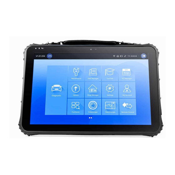
Page 22: Diagnostic Menu
VCI Manager - leads to screens for making Bluetooth pairing of VCI ● dongle and tablet, updating the VCI firmware and binding/unbinding VCI dongle. Update - leads to screens for Foxwell ID registration and updating the ● scanner. Shop Manager - allows the technicians to manage the workshop ●... -
Page 23: Vehicle Identification
Figure 3-8 Sample Diagnostic Menu Screen Name Description Back Back to the Application Menu or last page. Shortcut for VIN reading menu, which typically includes Automatic Read Manual Entry. Displays car makes from different origins like Area America, Asia, Europe and Chinese. Search Lets you search a vehicle make quickly. -
Page 24: Vin Reading
Not all identification options listed above are applicable to all vehicles. Available options may vary by vehicle manufacturer. 4.1 VIN Reading VIN button on the title bar is a shortcut for VIN reading menu, which includes Automatic Read and Manual Entry, eliminating the need for navigating through complicated car identification process. -
Page 25: Manual Entry
3. When the scan tool builds connection with the vehicle, the VIN number displays. If the Vehicle Specification or VIN code is correct, press the Confirm to continue. 4. If it takes too long to get the VIN code, press Cancel to stop and input the VIN manually. -
Page 26: Smart Vin
Smart VIN ● Manual Selection ● Figure 4-6 Sample Vehicle Entry Screen Name Button Description Home Back to the Application Menu. Settings A shortcut for Settings menu. Records the communication data between Data Logging the scan tool and the vehicle to help with troubleshooting of diagnostic failures. -
Page 27: Manual Vehicle Selection
Figure 4-7 Sample Vehicle Selection Screen 3. Choose Smart VIN option to start reading the VIN automatically. Figure 4-8 Sample Smart VIN Screen 4. After the scan tool builds connection to the vehicle, the VIN number displays. If the Vehicle Specification or VIN code is correct, press the OK to continue. -
Page 28: Diagnosis
Figure 4-9 Sample Manual Vehicle Selection Screen 5 Diagnosis This section illustrates how to use the scanner to read and clear diagnostic trouble codes, view live data readings and ECU information on controllers installed, perform special functions such as actuation and coding, and perform vehicle services and maintenance on Asia, European and USA vehicle brands. -
Page 29: Control Module Selection
5.1 Control Module Selection When you completed the identification of vehicle, you have to identify the control modules installed in the vehicle. There are two ways to identify the controllers installed in a car: Quick Scan ● Control Modules ● Figure 5-2 Sample Diagnosis Screen 5.1.1 Quick Scan Quick Scan performs an automatic system test to determine which control... - Page 30 3. At the end of successful automatic controller scan, a menu with a list of DTC displays and click button to the right to view DTC descriptions. Figure 5-4 Sample Quick Scan Complete Screen 4. Press Report to create an overview of installed control units and their system status, or press Save to save the report.
-
Page 31: Control Modules
Figure 5-6 Sample Report Screen Figure 5-7 Sample Erase Screen 5.1.2 Control Modules Control Modules displays all controllers available of the vehicle manufacturer. The controllers listed on the menu do not mean that they are installed on the vehicle. It is useful for technicians who are familiar with the vehicle specifications. -
Page 32: Diagnostic Operations
Figure 5-8 Sample Control Modules Screen 2. Select a system to test. When the scanner has established connection with the vehicle, the Function Menu displays. Figure 5-9 Sample Function Menu Screen 5.2 Diagnostic Operations After a system is selected and the scanner establishes communication with the vehicle, the Function Menu displays. -
Page 33: Read Codes
5.2.1 Read Codes Read Codes menu lets you read trouble codes found in the control unit. There are 4 types of code status: Present/Permanent/Current ● Pending ● History ● Self-diagnostic ● Present/Permanent/Current codes stored in a control module are used to help identify the cause of a trouble or troubles with a vehicle. - Page 34 Freeze Frame- select one fault code from the code list and click Freeze ● Frame button on the screen. The screen will display freeze frame data, a snapshot of critical vehicle operating conditions automatically recorded by the on-board computer at the time of the DTC set. It is a good function to help determine what caused the fault.
-
Page 35: Clear Codes
Figure 5-13 Sample DTC Help Screen 2. Slide up and down to view additional information when necessary. 3. Press Save to store DTC information. Press to print the information if need be. Press to exit. 5.2.2 Clear Codes Clear Codes menu lets you to clear all current and stored DTCs from a selected control module. -
Page 36: Live Data
Figure 5-14 Sample Function Menu Screen 2. Follow the on-screen instructions and answer questions about the vehicle being tested to complete the procedure. 3. Check the codes again. If any codes remain, repeat the Clear Codes steps. 5.2.3 Live Data Live Data menu lets you view real time PID data in text and plot formats, learn good sensor data and compare them with faulty data, and record live data from a selected vehicle electronic control module. - Page 37 Name Button Description Help To provide help information of a PID Record To make record of live data Save To save live data of current frame Pause To stop recording live data Table 5-1 Live Data Screen Button Screen 3. Swipe the screen up and down to view additional information when necessary.
-
Page 38: Ecu Information
Figure 5-18 Sample Multi-graphs Screen Merge Graph: merges multiple PID plots into one coordinate, so you can ● easily see how they affect each other, providing you with the most comprehensive and functional look at live data possible. Figure 5-19 Sample Merge Graph Screen 5.2.4 ECU Information ECU Information screen displays the identification data of the control module under test, such as the control module identification string and the... -
Page 39: Active Tests
Figure 5-20 Sample Function Menu Screen 2. A screen with detailed information of the selected control module displays. Figure 5-21 Sample ECU Information Screen 3. Press Save to store ECU information. Press to print the information if need be. Press to exit. - Page 40 shut down, turn the ignition to the run position, then re-initiate the actuator tests. IMPORTANT The tests activate a component, but they do not check if the component is working correctly. Make sure the components to be tested are in good condition and correctly mounted.
-
Page 41: Special Functions
Before running any tests, always observe the safety instructions provided in ● this manual and the warnings provided by the vehicle manufacturer. In addition, follow any warnings and descriptions provided on the scanner screens. ● Never run the tests while the vehicle is moving. 5.2.6 Special Functions These functions perform various component adaptations of the control module under test, allowing you to recalibrate or configure certain... -
Page 42: Coding And Programming
2. Select Service option from the Special Functions menu. A list of available services display. Figure 5-25 Sample Special Functions Screen 3. Select the service you want to perform. Follow on-screen instructions to make proper selections and operations to complete the tests. Figure 5-26 Sample Service Function Screen 5.3.2 Coding and Programming GT90 Max allows for the coding and programming of a replacement control... -
Page 43: Hot Functions
Figure 5-27 Sample Main Menu Screen 2. Select Programming option from the Special Functions menu. A list of available services display. Figure 5-28 Sample Special Functions Screen 3. Select the function you want to test. Follow on-screen instructions to make proper selections and operations to complete the tests 5.3.3 Hot Functions It is designed for most common used functions like battery configuration, oil... -
Page 44: Maintenance
Figure 5-29 Sample Special Functions Screen 3. Select the function you want to test. Follow on-screen instructions to make proper selections and operations to complete the tests Figure 5-30 Sample Hot Functions Screen 6 Maintenance This section gives brief instructions of the most commonly required service and maintenance operations. -
Page 45: Oil Light Reset
Gear Learn ● TPMS Relearn ● Odometer ● Injector Coding ● ABS Bleeding ● Key Programming/Immobilizer ● 6.1 Oil Light Reset Oil Light Reset menu allows you to reset the service lamps on the instrument cluster. The Service Indicator System is designed to alert the driver when the vehicle is due for a service. - Page 46 Typical special test options include: Deactivate/Activate SBC/EPB systems - allows to deactivate brakes for ● further service or maintenance work on brake systems or activate brakes when service or maintenance work on brake systems are completed. Adaptation on Audi A8 - allows to set new pad thickness of rear brakes ●...
-
Page 47: Battery Replacement (Brt)
6.3 Battery Replacement (BRT) BRT menu lets you to validate new battery, clear faults from the dashboard and display current battery details of the vehicle such as Audi, BMW, Citroen, Peugeot, Seat, Skoda, Volvo, VW and Ford. 1. Replace the old battery with the new one. Ensure the key is not in the ignition. -
Page 48: Steering Angle Sensor (Sas) Calibration
Using the throttle position sensors in the throttle body, the ECU learns the full open and full closed positions through various states (idle, part throttle, WOT) known as a Throttle Body Alignment (TBA). 6.6 Steering Angle Sensor (SAS) Calibration SAS Calibration menu let you perform calibration of the Steering Angle Sensor, which permanently stores the current steering wheel position as straight-ahead in the sensor EEPROM. -
Page 49: Injector Coding
6.11 Injector Coding Write injector actual code or rewrite code in the ECU to the injector code of the corresponding cylinder so as to more accurately control or correct cylinder injection quantity. After the ECU or injector is replaced, injector code of each cylinder must be confirmed or re-coded so that the cylinder can better identify injectors to accurately control fuel injection. -
Page 50: Image
Figure 7-1 Sample Data Manager Screen 7.1 Image Image option leads to screens for review of stored screenshots. In case a failure of GT90 Max application or the Android system occurs, please just take a screenshot and send it to our team to help with the troubleshooting. 7.1.1 How to Save an Image To take a screenshot: If want to save data of current screen, press... - Page 51 Figure 7-3 Sample Browse Picture Screen 3. To delete a picture, tap button Delete and answer OK to delete. Press Print to print the pictures and press Rename to change the picture name. Figure 7-4 Sample Edit Picture Screen 4. Press Edit to edit all pictures like Rename or Delete. Figure 7-5 Sample All Pictures Edit Screen Windows Diagnostic Platform GT90 Max User's Manual V1.01...
-
Page 52: Reports
7.2 Reports Reports option leads to screens for review of the vehicle test reports. You just need to press the Save icon on the test screen, add a description and press OK button to save. 7.2.1 How to Create a Report To create a report: 1. -
Page 53: Data Playback
3. Press Edit icon to edit all files like Rename or Delete the files. Figure 7-8 Sample Edit PDF Screen 7.3 Data Playback The Data Playback option leads to screens for review of recorded live data. Playing back a recording is just like using the scan tool on a live vehicle. It let you review live data in text, graph and graph merging formats. -
Page 54: Data Logging & Data Record
4. To view parameter graphs, press the Graph tab. And to merge the graphs, press the tab Merge Graph or press the tab Multi Graph to view multiple plots. Figure 7-10 Sample Graph Screen 5. Press Edit icon to Rename or Delete the records. 7.4 Data Logging &... -
Page 55: Vci Manager
2. Click the Data Logging icon again to stop the recording and data log record will be saved automatically. 3. Go to Data Manager -- Data Record to view the stored logs. 8 VCI Manager VCI Manager allows you to make Bluetooth pairing between the tablet and the VCI dongle, update VCI firmware and unbind a VCI dongle. -
Page 56: Bluetooth
8.2 Bluetooth During the Bluetooth pairing process, make sure the VCI dongle is correctly powered by either connected to a vehicle or connect to the tablet with the USB Type-B cable. To make Bluetooth pairing of the VCI dongle and the tablet 1. - Page 57 Figure 8-4 Sample Unbind Prompt Screen To bind a new VCI dongle: 1. Connect the VCI dongle with GT90 Max tablet via USB cable. Figure 8-5 Sample Bind Prompt Screen 2. When system database initialization finished, you can use the tablet normally.
-
Page 58: Registration And Update
The scanner can be updated to keep you stay current with the latest development of diagnosis. This section illustrates how to register and update your scan tool. You can register both on Foxwell website or by the built-in update client. - Page 59 Figure 9-2 Sample ID Registration Screen 3. Enter one of your email addresses as your user ID and click the Send Code button. We will send a 4-digit verification code to the email you just entered. Find the security code in your mailbox, input the code, create a password and click Free Registration to complete.
- Page 60 Figure 9-4 Sample Registration Done Screen 5. The serial number will be recognized automatically and click Submit to activate the scanner. Figure 9-5 Sample Product Activation Screen 6. The product is registered successfully. Figure 9-6 Sample Activation Done Screen Windows Diagnostic Platform GT90 Max User's Manual V1.01...
-
Page 61: Register Through Website
9.1.2 Register through Website To register through our website: 1. Visit Foxwell official website www.foxwelltech.us and press Register icon, or go to the registration page by selecting Support from home page and then click Register. Figure 9-7 Sample Website Register Screen Figure 9-8 Sample Website Register Screen 2. -
Page 62: Update
Figure 9-9 Sample Create Account Screen 3. Sign in to the Member Center, click New Registration, input the right serial number and click Submit to activate the product. Figure 9-10 Sample Product Register Screen 9.2 Update To update the diagnostic application: 1. -
Page 63: Settings
Figure 9-11 Sample Update Screen 10 Settings This section illustrates how to program the scanner to meet your specific needs. When Settings application is selected, a menu with available service options displays. Menu options typically include: Unit ● Language ● Push Message ●... -
Page 64: Language
It is highly recommended to enable it all the time, so you won’t miss out any new updates from Foxwell. To enable/disable Push Message: 1. Press Settings from home screen of the GT90 Max diagnostic application. -
Page 65: Automatic Update
Figure 10-2 Sample Push Message Setting Screen 10.4 Automatic Update This option allows you to enable/disable automatic update notice. If it is enabled, an orange update mark will show on the upper right of the diagnostic software icon whenever there is a new version available. Figure 10-3 Sample Update Remark Screen 10.5 Show Disclaimer This option allows you to turn on/off Disclaimer notice. -
Page 66: System Settings
10.7 System Settings This option provides you a direct access to the Windows system settings, like sound, display, system security and etc. 10.8 Storage Path Selection This option lets you to choose the file storage path when saving a file or data. 10.9 Uninstall Vehicle Software This option allows you to uninstall the vehicle software installed in the scanner. -
Page 67: Print Settings
Figure 10-5 Sample Uninstall Vehicle Software Screen 10.10 Print Settings This option allows you to print any data or information anywhere and anytime either via PC network or Wi-Fi. To setup the printer connection: 1. Tap the Settings application on home screen of GT90 Max. 2. -
Page 68: About
Figure 10-7 Sample of Printer Screen NOTE Please make sure the printer and the GT90 Max in the same Wi-Fi or Network when printing. 10.11 About Selecting About option opens a screen that shows information about the GT90 Max, such as serial number, hardware and software version and etc. To view information of your scan tool: 1. -
Page 69: Vehicle History
When Shop Manager application is selected, a menu with available service options displays. Menu options typically include: Vehicle History ● Workshop Information ● Figure 11-1 Sample Shop Manager Screen 11.1 Vehicle History This function keeps records of tested vehicles, including vehicle information and the fault codes from previous diagnostic sessions etc. -
Page 70: My Account
Figure 11-3 Sample Workshop Information Screen 12 My Account This section displays the information related to your account and product. When My Account application is selected, a menu with available options displays. Menu options typically include: My Account ● My Products ●... -
Page 71: M Yproducts
This option let you activate a new product and manage activated products including serial number and expiration date. Figure 12-3 Sample My Products Screen 12.3 Complaints This option allows you send your compliant or feedback about Foxwell products. Windows Diagnostic Platform GT90 Max User's Manual V1.01... -
Page 72: Remote Support
Figure 12-4 Sample Feedback & Suggestions Screen 13 Remote Support Remote Control enables you to get remote support from Foxwell with TeamViewer when you have issues with Foxwell products. If you need our team to remote control your GT90 Max, 1. -
Page 73: Technical Data
Figure 13-2 Sample QuickSupport Screen 3. Send your ID to us to let our team to take control your tablet. 14 Technical Data This option provides you with the quick access to technical data like wiring diagram and repair tips provided by HaynesPro, AutoData or others. Figure 14-1 Sample Technical Data Screen 15 Tutorials This option provides you with training videos and guides about how to use... -
Page 74: Functions
Figure 15-1 Sample Tutorials Screen 16 Functions This option links to function search page which lets you search the supported vehicle models, systems and functions. Figure 16-1 Sample Functions Screen Windows Diagnostic Platform GT90 Max User's Manual V1.01...
Need help?
Do you have a question about the GT90Max and is the answer not in the manual?
Questions and answers