Table of Contents
Advertisement
Trademarks
FOXWELL is trademark of Shenzhen Foxwell Technology Co., Ltd.
All other marks are trademarks or registered trademarks of their respective
holders.
Copyright Information
©2019 Shenzhen Foxwell Technology Co., Ltd.
All rights reserved.
Disclaimer
The information, specifications and illustrations in this manual are based on the
latest information available at the time of printing.
Foxwell reserves the right to make changes at any time without notice.
Visit our website at
www.foxwelltech.us
For Technical Assistance, send us email at
support@foxwelltech.com
1
Premier Diagnostic Platform i70Pro User's Manual V1.01
Advertisement
Table of Contents

Subscribe to Our Youtube Channel
Related Manuals for Foxwell i70 Pro


Summary of Contents for Foxwell i70 Pro
- Page 1 Disclaimer The information, specifications and illustrations in this manual are based on the latest information available at the time of printing. Foxwell reserves the right to make changes at any time without notice. Visit our website at www.foxwelltech.us For Technical Assistance, send us email at support@foxwelltech.com...
-
Page 2: One-Year Limited Warranty
FOXWELL. 3 The customer shall bear the cost of shipping the product to FOXWELL. And FOXWELL shall bear the cost of shipping the product back to the customer after the completion of service under this limited warranty. - Page 3 The customer will be billed for any parts or labor charges not covered by this limited warranty. d) FOXWELL will repair the Product under the limited warranty within 30 days after receipt of the product. If FOXWELL cannot perform repairs covered...
- Page 4 consequential damages, so certain of the above limitations or exclusions may not apply to you (the Consumer). This limited warranty gives the Consumer specific legal rights and the Consumer may also have other rights which vary from state to state. Premier Diagnostic Platform i70Pro User's Manual V1.01...
-
Page 5: Safety Information
Safety Information For your own safety and the safety of others, and to prevent damage to the equipment and vehicles, read this manual thoroughly before operating your tool. The safety messages presented below and throughout this user’s manual are reminders to the operator to exercise extreme care when using this device. - Page 6 ● Fuel, oil vapors, hot steam, hot toxic exhaust gases, acid, refrigerant and other debris produced by a malfunction engine can cause serious injury or death. Do not use the tool in areas where explosive vapor may collect, such as in below-ground pits, confined areas, or areas that are less than 18 inches (45 cm) above the floor.
-
Page 7: Table Of Contents
Table of Contents ONE-YEAR LIMITED WARRANTY........................2 SAFETY INFORMATION............................ 5 SAFETY MESSAGE CONVENTIONS USED....................5 IMPORTANT SAFETY INSTRUCTIONS......................5 1 USING THIS MANUAL..........................10 1.1 B ..............................10 1.2 S ..........................10 YMBOLS AND CONS 1.2.1 Solid Spot............................10 1.2.2 Arrow Icon............................10 1.2.3 Note and Important Message......................10 2 INTRODUCTION.............................11 2.1 S... - Page 8 4.1.2.1 Scan VIN Plate........................26 4.1.2.2 Scan Barcode/QR Code of VIN................... 27 4.1.2.3 Photo Recognition........................28 4.1.3 Manual Entry.............................29 4.2 M ........................... 30 ANUAL ELECTION 4.2.1 Smart VIN............................31 4.2.2 Manual Vehicle Selection....................... 32 4.3 V ............................33 EHICLE ISTORY 5 DIAGNOSIS..............................34 5.1 C .........................
- Page 9 7.1.1 How to Save an Image........................59 7.1.2 Review Image........................... 59 7.2 PDF R ..............................61 EPORT 7.2.1 How to Create a PDF Report......................61 7.2.2 Review PDF Report......................... 61 7.3 D ............................62 LAYBACK 7.4 D & D ......................63 OGGING ECORD 8 VCI MANAGER...............................
-
Page 10: Using This Manual
1 Using This Manual We provide tool usage instructions in this manual. Below are the conventions we used in the manual. 1.1 Bold Text Bold text is used to highlight selectable items such as buttons and menu options. Example: Select Diagnostic from home screen of the i70Pro application. 1.2 Symbols and Icons 1.2.1 Solid Spot Operation tips and lists that apply to specific tool are introduced by a solid... -
Page 11: Introduction
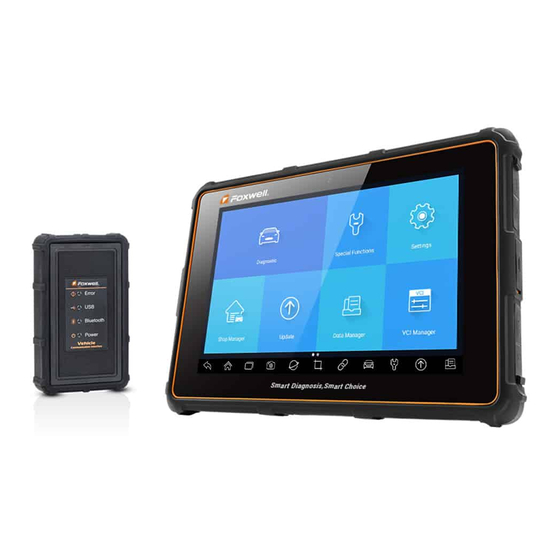
NOTE Test results do not necessarily indicate a faulty component or system. Important IMPORTANT indicates a situation, which if not avoided, may result in damage to the test equipment or vehicle. Example: IMPORTANT Do not soak scanner as water might find its way into the scanner. 2 Introduction The latest Android tablet scanner i70Pro delivers faster and smarter diagnosis for workshops and technicians. - Page 12 2 Power Indicator - indicates the power status of the scanner. 3 Charging Indicator - indicates the charging status of the scanner. Figure 2-2 Back View 4 Rear-Facing Camera - takes pictures of VIN number, faulty parts and plates and shoots test videos. Figure 2-3 Top View 5 Power Switch - turns on the scanner, goes to sleep mode or wake up the scanner from sleep mode, press and hold for 3 seconds for emergency...
-
Page 13: Vci Dongle Descriptions
IMPORTANT Do not use solvents such as alcohol to clean display. Use a mild nonabrasive detergent and a soft cotton cloth. 2.2 VCI Dongle Descriptions i70Pro connects to the vehicle and get data through the VCI dongle either by Bluetooth or USB communication. Figure 2-5 Front View of VCI dongle 1 Error Light - illuminates constantly when serious hardware failure occurs. - Page 14 5 Vehicle Data Connector - provides connection between vehicle and the VCI dongle through the 16 pin diagnostic cable. Figure 2-7 Bottom View of VCI 6 USB Port - provides USB connection between the VCI dongle and i70Pro tablet. Premier Diagnostic Platform i70Pro User's Manual V1.01...
-
Page 15: Accessories
2.3 Accessories This section lists the accessories that go with the scanner. If you find any of the following items missing from your package, contact your local dealer for assistance. Table 2-1 Accessories Premier Diagnostic Platform i70Pro User's Manual V1.01... -
Page 16: Technical Specifications
2.4 Technical Specifications Item Description Touch Screen 8’’ diagonal, daylight readable color LCD screen, 1280*800 pixel Operation Android System Processor MT8163 (ARM Cortex, a53x4, 1.3GHz) Memory 2GB DDR3L SSD Hard drive 32GB System Type 32-bit operating Systems, x64-based processor Display Backlit 1280*800 pixel 8”... -
Page 17: Internal Battery Pack
3.1.1 Internal Battery Pack The i70Pro tablet can be powered with the internal rechargeable battery. The fully charged battery is capable of providing power for 14 hours of continuous operation. NOTE Please turn off the tablet to save power when not use. 3.1.2 External Power Supply The tablet can also be powered from a wall socket using the USB charging adapter. -
Page 18: Vci Connection
Figure 3-2 Sample Bluetooth Communication Screen Figure 3-3 Sample USB Communication Screen Please refer to Chapter 3.3.1.1about the details of how to connect via Bluetooth and Chapter 3.3.1.2 about the details of how to connect via USB cable. 3. Check the VCI Indicator status at the toolbar. If the button turns to green, the i70Pro is ready to start vehicle diagnosis. - Page 19 To build Bluetooth connection: 1. Power up the tablet. 2. Go to VCI Manager and then Bluetooth. Click Connect and the VCI dongle will connect to the tablet automatically. Figure 3-4 Sample VCI Manager Screen Figure 3-5 Sample Bluetooth Connection Screen 3.
-
Page 20: Usb Communication
Figure 3-6 Sample VCI Indicator Status Screen NOTE If the VCI Indicator isn’t green, it indicates that the signal strength of the transmitter is too weak to be detected. In this case, try to get closer to the device, or check the connection of VCI dongle, and remove all possible objects that cause signal interference 3.3.1.2 USB Communication The USB connection is a simple and quick way to establish communication... -
Page 21: Application Menu
Data Manager - leads to screens for saved screenshots, pictures and test ● reports, and playing back live data, as well as debug logging data. Update - leads to screens for Foxwell ID registration and updating the ● scanner. VCI Manager - leads to screens for making Bluetooth pairing of VCI ●... - Page 22 Back Back to the previous screen. Home Returns to Home screen of Android System. Allows for browsing, switching and closing active Multitask applications. Camera Takes a photo or picture. Browser Opens the built-in browser. Screenshot Captures screens. Shortcut for VCI Manager menu from any screen of VCI Indicator the tablet;...
-
Page 23: Diagnostic Menu
3.4.3 Diagnostic Menu Touch Diagnostic at the i70Pro application menu, and the Diagnostic menu will display. The operations of the buttons on Diagnostic menu are described in the below table. Figure 3-9 Sample Diagnostic Menu Screen Name Description Home Back to the Application Menu. Shortcut for VIN reading menu, which typically includes Automatic Read, Scan VIN and Manual Entry. -
Page 24: Vin Reading
prompts and make a series of choices. Each selection you make advances you to the next screen. Exact procedures may vary somewhat by vehicle. It typically identifies a vehicle by any of the following means: VIN Reading ● Manual Selection ●... - Page 25 Figure 4-2 Sample Automatic Read Screen 3. When the scan tool builds connection with the vehicle, the VIN number displays. If the Vehicle Specification or VIN code is correct, press the OK to continue. Figure 4-3 Sample Automatic Read Screen 4.
-
Page 26: Scan Vin
Figure 4-4 Sample Manual Entry Screen 4.1.2 Scan VIN Scan VIN allows identifying a vehicle by scanning the VIN plate of the vehicle, barcode, QR code or photo recognition. 4.1.2.1 Scan VIN Plate To identify a vehicle by Scan VIN Plate: 1. -
Page 27: Scan Barcode/Qr Code Of Vin
Figure 4-7 Sample Modify VIN Screen 4. If failed, please click Close to quit and input the VIN manually. 4.1.2.2 Scan Barcode/QR Code of VIN To identify a vehicle by Scan QR Code: 1. Select Diagnostic from home screen of the i70Pro application. 2. -
Page 28: Photo Recognition
Figure 4-9 Sample Scan QR Code Screen Figure 4-10 Sample VIN Confirmation Screen 4. If failed, please click Close to quit and input the VIN manually. 4.1.2.3 Photo Recognition To identify a vehicle by Photo Recognition: 1. Select Diagnostic from home screen of the i70Pro application. 2. -
Page 29: Manual Entry
Figure 4-11 Sample Photo Recognition Screen Figure 4-12 Sample VIN Confirmation Screen Figure 4-13 Sample Modify VIN Screen 4. If failed, please click Close to quit and input the VIN manually. 4.1.3 Manual Entry Manual Entry allows to identify a vehicle by inputting VIN manually. To identify a vehicle by Manual Entry: Premier Diagnostic Platform i70Pro User's Manual V1.01... -
Page 30: Manual Selection
1. Select Diagnostic from home screen of the i70Pro application. 2. Click VIN and choose Manual Entry from the option list. 3. Press Keyboard button to input a valid VIN code and press OK to continue. Figure 4-14 Sample Manual Entry Screen 4.2 Manual Selection Select vehicle brand you are to test, and two ways of getting to the diagnostic operations are available. -
Page 31: Smart Vin
Settings A shortcut for Settings menu. Records the communication data between Data Logging the scan tool and the vehicle to help with troubleshooting of diagnostic failures. Print Print the test data and report. Takes screenshot of test data or report and Screenshot save them for later analysis. -
Page 32: Manual Vehicle Selection
Figure 4-17 Sample Smart VIN Screen 4. After the scan tool builds connection to the vehicle, the VIN number displays. If the Vehicle Specification or VIN code is correct, press the OK to continue. If incorrect, please enter a valid VIN number manually. 4.2.2 Manual Vehicle Selection Manual Selection identifies a vehicle by making several selections according to certain VIN characters, such as model year, and engine type. -
Page 33: Vehicle History
4.3 Vehicle History Vehicle History keeps records of tested vehicles and allows restarting the diagnosis of a vehicle without the need to do vehicle identification again. To identify a vehicle by Vehicle History: 1. Select Diagnostic from home screen of the i70Pro application. 2. -
Page 34: Diagnosis
5 Diagnosis This section illustrates how to use the scanner to read and clear diagnostic trouble codes, view live data readings and ECU information on controllers installed, perform special functions such as actuation and coding, and perform vehicle services and maintenance on Asia, European and USA vehicle brands. -
Page 35: Quick Scan
Figure 5-2 Sample Diagnosis Screen 5.1.1 Quick Scan Quick Scan performs an automatic system test to determine which control modules are installed on the vehicle and provides diagnostic trouble codes (DTCs) overview. Depending on the number of control modules, it may take a few minutes to complete the test. - Page 36 Figure 5-4 Sample Quick Scan Complete Screen 4. Press Report to create an overview of installed control units and their system status, or press Save to save the report. Press Erase to clear the information. Figure 5-5 Sample DTC Save Screen Figure 5-6 Sample Report Screen Premier Diagnostic Platform i70Pro User's Manual V1.01...
-
Page 37: Control Modules
Figure 5- 7 Sample Erase Screen 5. When running auto scanning, you can press Pause and select the system you would like to test. When the scanner has established connection with the vehicle, the Function Menu displays. Figure 5-8 Sample Function Menu Screen 5.1.2 Control Modules Control Modules displays all controllers available of the vehicle manufacturer. -
Page 38: Diagnostic Operations
Figure 5-9 Sample Control Modules Screen 2. Select a system to test. When the scanner has established connection with the vehicle, the Function Menu displays. Figure 5-10 Sample Function Menu Screen 5.2 Diagnostic Operations After a system is selected and the scanner establishes communication with the vehicle, the Function Menu displays. -
Page 39: Read Codes
5.2.1 Read Codes Read Codes menu lets you read trouble codes found in the control unit. There are 4 types of code status: Present/Permanent/Current ● Pending ● History ● Self-diagnostic ● Present/Permanent/Current codes stored in a control module are used to help identify the cause of a trouble or troubles with a vehicle. - Page 40 snapshot of critical vehicle operating conditions automatically recorded by the on-board computer at the time of the DTC set. It is a good function to help determine what caused the fault. Figure 5-12 Sample Trouble Code Screen Figure 5-13 Sample Freeze Frame Screen Help - select one fault code from the code list and click Help button on the ●...
-
Page 41: Clear Codes
Figure 5-14 Sample DTC Help Screen 2. Slide up and down to view additional information when necessary. 3. Press Save to store DTC information. Press to print the information if need be. Press to exit. 5.2.2 Clear Codes Clear Codes menu lets you to clear all current and stored DTCs from a selected control module. -
Page 42: Live Data
2. Follow the on-screen instructions and answer questions about the vehicle being tested to complete the procedure. 3. Check the codes again. If any codes remain, repeat the Clear Codes steps. 5.2.3 Live Data Live Data menu lets you view real time PID data in text and plot formats, learn good sensor data and compare them with faulty data, and record live data from a selected vehicle electronic control module. - Page 43 Figure 5-17 Sample Live Data Screen Name Button Description Help To provide help information of a PID To move a data line to the top of Data List To Top screen To view the previous live data records or History test reports Record To make record of live data...
- Page 44 Figure 5-18 Sample Learn Mode Screen Compare Mode - If that vehicle comes in is with a problem, you can easily ● compare the faulty sensor and parameter readings to the good readings, and you will be alarmed when a faulty sensor reading is detected. Figure 5-19 Sample Live Data Screen 3.
- Page 45 Figure 5-20 Sample PID Graph Screen Multi-graphs: displays the parameters in waveform graphs, giving you ● the ‘real picture’ of what’s going on in the vehicle. You can view up to 4 parameter graphs simultaneously. Figure 5-21 Sample Multi-graphs Screen Merge Graph: merges multiple PID plots into one coordinate, so you can ●...
-
Page 46: Custom List
5.2.3.2 Custom List Custom List menu lets you to minimize the number of PIDs on the data list and focus on any suspicious or symptom-specific data parameters. To create a custom data list: 1. Press Custom List from the menu to display all available parameters from the selected control module. -
Page 47: Active Tests
1. Press ECU Information from Select Diagnostic Function menu. Figure 5-25 Sample Function Menu Screen 2. A screen with detailed information of the selected control module displays. Figure 5-26 Sample ECU Information Screen 3. Press Save to store ECU information. Press to print the information if need be. - Page 48 shut down, turn the ignition to the run position, then re-initiate the actuator tests. IMPORTANT The tests activate a component, but they do not check if the component is working correctly. Make sure the components to be tested are in good condition and correctly mounted.
-
Page 49: Special Functions
Before running any tests, always observe the safety instructions provided in ● this manual and the warnings provided by the vehicle manufacturer. In addition, follow any warnings and descriptions provided on the scanner screens. ● Never run the tests while the vehicle is moving. 5.2.6 Special Functions These functions perform various component adaptations of the control module under test, allowing you to recalibrate or configure certain... -
Page 50: Coding And Programming
2. Select Service option from the Special Functions menu. A list of available services display. Figure 5-30 Sample Special Functions Screen 3. Select the service you want to perform. Follow on-screen instructions to make proper selections and operations to complete the tests. Figure 5-31 Sample Service Function Screen 5.3.2 Coding and Programming i70Pro allows for the coding and programming of a replacement control... - Page 51 Figure 5-32 Sample Main Menu Screen 2. Select Programming option from the Special Functions menu. A list of available services display. Figure 5-33 Sample Special Functions Screen 3. Select the function you want to test. Follow on-screen instructions to make proper selections and operations to complete the tests Premier Diagnostic Platform i70Pro User's Manual V1.01...
-
Page 52: Hot Functions
Figure 5-34 Sample Programming Screen 5.3.3 Hot Functions It is designed for most common used functions like battery configuration, oil light reset and provides quick access to service functions for the technicians. To start a test: 1. Select Special Functions from main menu and press ENTER to confirm. Figure 5-35 Sample Main Menu Screen 2. -
Page 53: Maintenance
Figure 5-37 Sample Hot Functions Screen 6 Maintenance This section gives brief instructions of the most commonly required service and maintenance operations. Typical service operation screens are a series of menu driven executive commands. Follow on-screen instructions to complete the operation. Available service and maintenance options include: Oil Light Reset ●... -
Page 54: Electronic Parking Brake (Epb) Service
Oil Reset with One Button - applicable to GM models only. It offers quick ● and simple oil service reset with the click of one button. Manual Reset - almost all Asian vehicles and most American and ● European vehicles have mechanical oil service indicator reset. The service tool does not have to communicate with the vehicle being tested, but guides you to complete the service manually by providing step-by-step on-screen instructions. -
Page 55: Battery Replacement (Brt)
Perform activation/service work on Volvo PBM vehicles – allows to ● perform installation check, applying parking brake, releasing parking brake, activating service mode and exiting service mode. Reset memory on Toyota EPB vehicles – allows to clear the learned ● memory of the EPB ECU. -
Page 56: Diesel Particulate Filter (Dpf) Regeneration
3. Boost the device and select BRT; it will display all the vehicle makes available. Choose your vehicle make and follow the scanner instruction to start. Sensor calibration on Honda EPB vehicles - allows to program the ● current output value of each sensor into the electric parking brake unit. Perform BRT on Citroen/Peugeot cars –... -
Page 57: Continuous Variable Transmission (Cvt)
6.7 Continuous Variable Transmission (CVT) This function is used to reset the compensation code and initialize the ECT after a solenoid valve or valve body assembly has been replaced. 6.8 Gear Learning The crankshaft position sensor learns crankshaft tooth machining tolerance and saves to the computer to more accurately diagnose engine misfires. -
Page 58: Key Programming/Immobilizer
pedal. Air trapped in the lines, calipers or wheel cylinders will make the pedal feel soft and spongy. Air is compressible, so when the brakes are applied any air bubbles in the system must first be compressed before the hydraulic fluid will transmit pressure to apply the brakes. -
Page 59: How To Save An Image
7.1.1 How to Save an Image To take a screenshot: 1. If want to save data of current screen, press at the title bar to take a screenshot. Figure 7-2 Sample Screenshot Screen 2. Add a description of the image, and press the OK to save. Figure 7-3 Sample Screenshot Screen 7.1.2 Review Image To review the screenshots:... - Page 60 Figure 7-4 Sample Browse Picture Screen 3. To delete a picture, tap button Delete and answer OK to delete. Press Print to print the pictures and press Rename to change the picture name. Figure 7-5 Sample Edit Picture Screen 4. Long press the screen to edit all pictures like Rename or Delete. Figure 7-6 Sample All Pictures Edit Screen Premier Diagnostic Platform i70Pro User's Manual V1.01...
-
Page 61: Pdf Report
7.2 PDF Report PDF option leads to screens for review of the vehicle test reports. You just need to press the PDF icon on the test screen, add a description and press OK button to save. 7.2.1 How to Create a PDF Report To create a PDF report: 1. -
Page 62: Data Playback
Figure 7-9 Sample Edit PDF Screen 7.3 Data Playback The Data Playback option leads to screens for review of recorded live data. Playing back a recording is just like using the scan tool on a live vehicle. It let you review live data in text, graph and graph merging formats. Playback speed and direction (forward or reverse) can also be controlled. -
Page 63: Data Logging & Data Record
Figure 7-11 Sample Graph Screen 5. To move forward or reverse back of the playing, just drag the progress bar forward or reverse. To stop, press the Pause button. Figure 7-12 Sample Edit Data Playback Screen 6. Long press the record to Rename or Delete the records. 7.4 Data Logging &... -
Page 64: Vci Manager
Figure 7-13 Sample Data Logging Screen 2. Click the Data Logging icon again to stop the recording and data log record will be saved automatically. 3. Go to Data Manager -- Data Record to view the stored logs. 8 VCI Manager VCI Manager allows you to make Bluetooth pairing between the tablet and the VCI dongle, update VCI firmware and unbind a VCI dongle. -
Page 65: Update Firmware
1. Connect the VCI dongle with a vehicle via diagnostic cable or connect to the tablet with the USB Type-B cable. 2. Click the VCI Manager application on the i70Pro Menu. 3. Select Bluetooth option from the list. 4. Select the right device with the i70Pro serial number from the list. 5. -
Page 66: Unbind Avci Dongle
Figure 8-3 Sample Update Prompt Screen 8.3 Unbind a VCI dongle This option allows you to unbind a VCI dongle when the VCI dongle is defective or stolen. To unbind a VCI dongle: 1. Click the VCI Manager application on the i70Pro Menu. Figure 8-4 Sample VCI Manager Screen 2. - Page 67 Figure 8-5 Sample Unbind Prompt Screen To bind a new VCI dongle: 1. Connect the VCI dongle with i70Pro tablet via USB cable. Figure 8-6 Sample Bind Prompt Screen 2. When system database initialization finished, you can use the tablet normally.
-
Page 68: Registration And Update
The scanner can be updated to keep you stay current with the latest development of diagnosis. This section illustrates how to register and update your scan tool. You can register both on Foxwell website or by the built-in update client. - Page 69 Figure 9-2 Sample ID Registration Screen 3. Enter one of your email addresses as your user ID and click the Send Code button. We will send a 4-digit verification code to the email you just entered. Find the security code in your mailbox, input the code, create a password and click Free Registration to complete.
- Page 70 Figure 9-4 Sample Registration Done Screen 5. The serial number will be recognized automatically and click Submit to activate the scanner. Figure 9-5 Sample Product Activation Screen 6. The product is registered successfully. Figure 9-6 Sample Activation Done Screen Premier Diagnostic Platform i70Pro User's Manual V1.01...
-
Page 71: Register Through Website
9.1.2 Register through Website To register through our website: 1. Visit Foxwell official website www.foxwelltech.us and press Register icon, or go to the registration page by selecting Support from home page and then click Register. Figure 9-7 Sample Website Register Screen Figure 9-8 Sample Website Register Screen 2. -
Page 72: Update
Figure 9-9 Sample Create Account Screen 3. Sign in to the Member Center, click New Registration, input the right serial number and click Submit to activate the product. Figure 9-10 Sample Product Register Screen 9.2 Update To update the diagnostic application: 1. -
Page 73: Settings
Figure 9-11 Sample Update Screen 10 Settings This section illustrates how to program the scanner to meet your specific needs. When Settings application is selected, a menu with available service options displays. Menu options typically include: Unit ● Language ● Push Message ●... -
Page 74: Push Message
It is highly recommended to enable it all the time, so you won’t miss out any new updates from Foxwell. To enable/disable Push Message: 1. Press Settings from home screen of the i70Pro diagnostic application. -
Page 75: Automatic Update
10.4 Automatic Update This option allows you to enable/disable automatic update notice. If it is enabled, an orange update mark will show on the upper right of the diagnostic software icon whenever there is a new version available. Figure 10-3 Sample Update Remark Screen 10.5 System Settings This option provides you a direct access to the Android system settings, like sound, display, system security and etc. -
Page 76: Print Settings
Figure 10-4 Sample Uninstall Vehicle Software Screen 4. Press Cancel to quit or and press OK to uninstall. Figure 10-5 Sample Uninstall Vehicle Software Screen 10.8 Print Settings This option allows you to print any data or information anywhere and anytime either via PC network or Wi-Fi. - Page 77 Figure 10-6 Sample Print Settings Screen 3. Tap Print Plugin Manager and turn on the Mopria Print Service, then i70Pro will search for available printers automatically. Figure 10-7 Sample Print Service Manager Screen Figure 10-8 Sample Setting of Print Service Manager Screen 4.
-
Page 78: About
Figure 10-9 Sample of Printer Screen 5. Choose the file or report you want to print and press the print icon Figure 10-10 Sample of File Printing Screen NOTE 1. Please make sure the printer and the i70Pro in the same Wi-Fi or Network when printing. -
Page 79: Shop Manager
Figure 10-11 Sample Tool Information Screen 11 Shop Manager This section illustrates how to manage the workshop information, vehicle test records and customer information. When Shop Manager application is selected, a menu with available service options displays. Menu options typically include: Vehicle History ●... -
Page 80: Workshop Information
Figure 11-2 Sample Vehicle History Screen 11.2 Workshop Information The Workshop Information allows you to edit, input and save the detailed workshop information, such as shop name, slogan, address, phone number and more. It will show as the header of the printed documents when printing vehicle diagnostic reports and other test files. -
Page 81: My Account
Feedback and suggestions ● Figure 12-1 Sample My Account Screen 12.1 My Account My Account option allows you to check and modify your account information including user name, e-mail, telephone, address and so on. Figure 12-2 Sample My Account Screen 12.2 My Products This option let you activate a new product and manage activated products including serial number and expiration date. -
Page 82: Push Message
Figure 12-3 Sample My Products Screen 12.3 Push Message It will display all messages you got from Foxwell including software update notice and product news. 12.4 Feedback and suggestions This option allows you to log on your e-mail and send feedback and suggestions about Foxwell products. -
Page 83: Remote Support
13 Remote Support Remote Control enables you to get remote support from Foxwell with TeamViewer when you have issues with Foxwell products. If you need our team to remote control your i70Pro, 1. Click the Remote Control icon on the main menu of the i70Pro to start TeamViewer. - Page 84 Figure 14-1 Sample Technical Data Screen Premier Diagnostic Platform i70Pro User's Manual V1.01...
Need help?
Do you have a question about the i70 Pro and is the answer not in the manual?
Questions and answers