Table of Contents
Advertisement
Quick Links
Trademarks
FOXWELL is trademark of Shenzhen Foxwell Technology Co., Ltd.
All other marks are trademarks or registered trademarks of their respective
holders.
Copyright Informationn
©2021 Shenzhen Foxwell Technology Co., Ltd.
All rights reserved.
Disclaimer
The information, specifications and illustrations in this manual are based on the
latest information available at the time of printing.
Foxwell reserves the right to make changes at any time without notice.
Visit our website at
www.foxwelltech.us
For Technical Assistance, send us email at
support@foxwelltech.com
1
Automotive Diagnostic & TPMS Platform GT75TS User's Manual V1.01
Advertisement
Table of Contents

Related Manuals for Foxwell GT75TS


Summary of Contents for Foxwell GT75TS
- Page 1 Disclaimer The information, specifications and illustrations in this manual are based on the latest information available at the time of printing. Foxwell reserves the right to make changes at any time without notice. Visit our website at www.foxwelltech.us For Technical Assistance, send us email at support@foxwelltech.com...
-
Page 2: One-Year Limited Warranty
FOXWELL. 3 The customer shall bear the cost of shipping the product to FOXWELL. And FOXWELL shall bear the cost of shipping the product back to the customer after the completion of service under this limited warranty. - Page 3 The customer will be billed for any parts or labor charges not covered by this limited warranty. d) FOXWELL will repair the Product under the limited warranty within 30 days after receipt of the product. If FOXWELL cannot perform repairs covered...
- Page 4 (the Consumer). This limited warranty gives the Consumer specific legal rights and the Consumer may also have other rights which vary from state to state. Automotive Diagnostic & TPMS Platform GT75TS User's Manual V1.01...
-
Page 5: Safety Information
● Do not exceed voltage limits between inputs specified in this user’s manual. ● Always wear ANSI approved goggles to protect your eyes from propelled objects as well as hot or caustic liquids. Automotive Diagnostic & TPMS Platform GT75TS User's Manual V1.01... - Page 6 ● Block drive wheels before testing with engine running. Put the transmission in park (for automatic transmission) or neutral (for manual transmission). And never leave a running engine unattended. ● Do not wear jewelry or loose fitting clothing when working on engine. Automotive Diagnostic & TPMS Platform GT75TS User's Manual V1.01...
-
Page 7: Table Of Contents
3.4.3 Diagnostic Menu..........................21 4 VEHICLE IDENTIFICATION......................... 21 4.1 VIN R .............................22 EADING 4.1.1 Automatic Read..........................22 4.1.2 Scan VIN............................24 4.1.2.1 Scan VIN Plate........................24 4.1.2.2 Scan Barcode/QR Code of VIN....................25 4.1.2.3 Photo Recognition........................26 Automotive Diagnostic & TPMS Platform GT75TS User's Manual V1.01... - Page 8 7.2 T ..........................53 RIGGER PERATIONS 7.3 L .............................. 61 EARN 8 NEW ENERGY..............................65 9 DATA MANAGER............................65 9.1 I ................................. 66 MAGE 9.1.1 How to Save an Image........................66 9.1.2 Review Image..........................67 Automotive Diagnostic & TPMS Platform GT75TS User's Manual V1.01...
- Page 9 ETTINGS 12.13 A ..............................85 BOUT 13 MY ACCOUNT.............................. 86 13.1 M ............................86 CCOUNT 13.2 M ............................86 RODUCTS 13.3 F ....................... 87 EEDBACK AND SUGGESTIONS 14 REMOTE SUPPORT............................ 88 Automotive Diagnostic & TPMS Platform GT75TS User's Manual V1.01...
-
Page 10: Using This Manual
Bold text is used to highlight selectable items such as buttons and menu options. Example: Select Diagnostic from home screen of the GT75TS application. 1.2 Symbols and Icons 1.2.1 Solid Spot Operation tips and lists that apply to specific tool are introduced by a solid spot ●. -
Page 11: Introduction
Do not soak scanner as water might find its way into the scanner. 2 Introduction The latest Android tablet scanner GT75TS delivers faster and smarter diagnosis for workshops and technicians. Through hardware and software upgrades, technical staff can now approach problems with greater speed and accuracy and produce comprehensive, professional reports. -
Page 12: Vci Dongle Descriptions
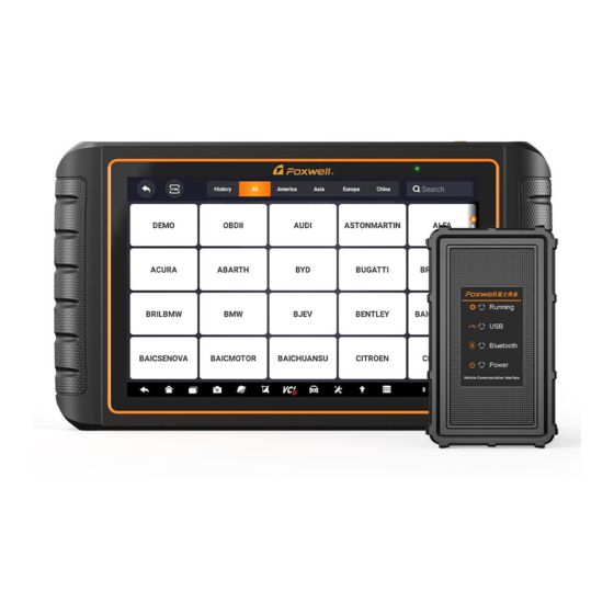
Do not use solvents such as alcohol to clean display. Use a mild nonabrasive detergent and a soft cotton cloth. 2.2 VCI Dongle Descriptions GT75TS connects to the vehicle and get data through the VCI dongle either by Bluetooth or USB communication. Automotive Diagnostic & TPMS Platform GT75TS User's Manual V1.01... - Page 13 5 Vehicle Data Connector - provides connection between vehicle and the VCI dongle through the 16 pin diagnostic cable. Figure 2-7 Bottom View of VCI 6 USB Port - provides USB connection between the VCI dongle and GT75TS tablet. Automotive Diagnostic & TPMS Platform GT75TS User's Manual V1.01...
-
Page 14: Accessories
Table 2-1 Accessories 2.4 Technical Specifications Item Description Touch Screen 10.1’’ diagonal, daylight readable color LCD screen, 1280*800 pixel Operation Android 9.0 System Processor Quad-Core, 2.0GHZ Memory 2GB, DDR3L SSD Hard drive 64GB Automotive Diagnostic & TPMS Platform GT75TS User's Manual V1.01... -
Page 15: Getting Started
● External Power Supply ● 3.1.1 Internal Battery Pack The GT75TS tablet can be powered with the internal rechargeable battery. The fully charged battery is capable of providing power for 8 hours of continuous operation. NOTE Please turn off the tablet to save power when not use. -
Page 16: Shutting Down The Scanner
3.2 Shutting Down the Scanner To shut down the scanner: 1. Press and hold the Power button of the GT75TS for 3 seconds. 2. Click the Power off to shut down or Restart to restart. 3.3 Establishing Vehicle Communication To establish communication with GT75TS: 1. -
Page 17: Vci Connection
3. Check the VCI Indicator status at the toolbar. If the button turns to green, the GT75TS is ready to start vehicle diagnosis. 3.3.1 VCI Connection The VCI dongle supports two ways of communication with the GT75TS tablet: ● Bluetooth Communication ●... -
Page 18: Usb Communication
USB Type B cable, and the VCI Indicator will turn green, indicating the dongle has connected to the tablet. 3.4 Screen Layout of Home Screen When the tablet boots up, press the GT75TS desktop icon to launch the diagnostic application. Automotive Diagnostic & TPMS Platform GT75TS User's Manual V1.01... -
Page 19: Application Menu
Oil light reset, EPB, BRT, DPF and etc. New Energy - leads to screens for new energy vehicle diagnosis. ● Update - leads to screens for Foxwell ID registration and updating the ● scanner. Data Manager - leads to screens for saved screenshots, pictures and test ●... - Page 20 Maintenance the tablet. Shortcut for Update menu from any screen of the Update tablet. Shortcut for Data Manager menu from any screen Data Manager of the tablet. Table 3-1 Tool Bar Automotive Diagnostic & TPMS Platform GT75TS User's Manual V1.01...
-
Page 21: Diagnostic Menu
3.4.3 Diagnostic Menu Touch Diagnostic at the GT75TS application menu, and the Diagnostic menu will display. The operations of the buttons on Diagnostic menu are described in the below table. Figure 3-7 Sample Diagnostic Menu Screen Name Description Back Back to the Application Menu. -
Page 22: Vin Reading
(VIN). To identify a vehicle by Automatic Read: 1. Select Diagnostic from home screen of the GT75TS application. 2. Click VIN and choose Automatic Read from the option list. Automotive Diagnostic & TPMS Platform GT75TS User's Manual V1.01... - Page 23 4. If it takes too long to get the VIN code, press Cancel to stop and input the VIN manually. Or if failed to identify the VIN, please input the VIN manually or click Cancel to quit. Automotive Diagnostic & TPMS Platform GT75TS User's Manual V1.01...
-
Page 24: Scan Vin
4.1.2.1 Scan VIN Plate To identify a vehicle by Scan VIN Plate: 1. Select Diagnostic from home screen of the GT75TS application. 2. Click VIN button and choose Scan VIN from the option list. 3. Find the VIN plate of your car, and put the VIN number into the scanning box. -
Page 25: Scan Barcode/Qr Code Of Vin
4.1.2.2 Scan Barcode/QR Code of VIN To identify a vehicle by Scan QR Code: 1. Select Diagnostic from home screen of the GT75TS application. 2. Click VIN button, choose Scan VIN from the option list and enable Scan QR Code at the lower left part of the screen. -
Page 26: Photo Recognition
4.1.2.3 Photo Recognition To identify a vehicle by Photo Recognition: 1. Select Diagnostic from home screen of the GT75TS application. 2. Click VIN button and choose Scan VIN from the option list. 3. Find the VIN plate, QR code or barcode of your car, and put the content number into the scanning box. -
Page 27: Manual Entry
Manual Entry allows to identify a vehicle by inputting VIN manually. To identify a vehicle by Manual Entry: 1. Select Diagnostic from home screen of the GT75TS application. 2. Click VIN and choose Manual Entry from the option list. 3. Press Keyboard button to input a valid VIN code and press OK to continue. -
Page 28: Manual Selection
Figure 4-15 Sample Vehicle Entry Screen Name Button Description Home Back to the Application Menu. Records the communication data between Data Logging the scan tool and the vehicle to help with troubleshooting of diagnostic failures. Automotive Diagnostic & TPMS Platform GT75TS User's Manual V1.01... -
Page 29: Smart Vin
(VIN). To identify a vehicle by Smart VIN: 1. Select Diagnostic from home screen of the GT75TS application. 2. A screen with vehicle manufacturers displays. Select the area where the vehicle manufacturer from. A menu of all vehicle manufacturers displays. -
Page 30: Manual Vehicle Selection
VIN characters, such as model year, and engine type. To identify a vehicle by manual vehicle selection: 1. Select Diagnostic from home screen of the GT75TS application. 2. A screen with vehicle manufacturers displays. Select the area where the vehicle manufacturer is from. -
Page 31: Vehicle History
To identify a vehicle by Vehicle History: 1. Select Diagnostic from home screen of the GT75TS application. 2. Select History button at the top of the diagnostic page and the diagnostic records will display. -
Page 32: Control Module Selection
When you completed the identification of vehicle, you have to identify the control modules installed in the vehicle. There are two ways to identify the controllers installed in a car: Quick Scan ● Control Modules ● Figure 5-2 Sample Diagnosis Screen Automotive Diagnostic & TPMS Platform GT75TS User's Manual V1.01... -
Page 33: Quick Scan
Figure 5-4 Sample Quick Scan Complete Screen 4. Press Report to create an overview of installed control units and their system status, or press Save to save the report. Press Erase to clear the information. Automotive Diagnostic & TPMS Platform GT75TS User's Manual V1.01... - Page 34 5. When running auto scanning, you can press Pause and select the system you would like to test. When the scanner has established connection with the vehicle, the Function Menu displays. Automotive Diagnostic & TPMS Platform GT75TS User's Manual V1.01...
-
Page 35: Control Modules
1. Press Control Modules from the menu and a controller menu displays. Figure 5-9 Sample Control Modules Screen 2. Select a system to test. When the scanner has established connection with the vehicle, the Function Menu displays. Automotive Diagnostic & TPMS Platform GT75TS User's Manual V1.01... -
Page 36: Diagnostic Operations
Pending codes are also referred to as maturing codes that indicate intermittent faults. If the fault does not occur within a certain number of drive cycles (depending on vehicle), the code clears from memory. If a fault occurs Automotive Diagnostic & TPMS Platform GT75TS User's Manual V1.01... - Page 37 DTC set. It is a good function to help determine what caused the fault. Automotive Diagnostic & TPMS Platform GT75TS User's Manual V1.01...
-
Page 38: Clear Codes
Also it erases all temporary ECU information, including freeze frame, so make sure that the selected system is completely checked and serviced by technicians and no vital information will be lost before clearing codes. NOTE Automotive Diagnostic & TPMS Platform GT75TS User's Manual V1.01... -
Page 39: Live Data
Menu options typically include: All Data ● Custom List ● Automotive Diagnostic & TPMS Platform GT75TS User's Manual V1.01... -
Page 40: All Data
To provide help information of a PID To Top To move a data line to the top of Data List screen To view the previous live data records or test History reports Automotive Diagnostic & TPMS Platform GT75TS User's Manual V1.01... - Page 41 Figure 5-20 Sample Live Data Screen 3. Swipe the screen up and down to view additional information when necessary. Automotive Diagnostic & TPMS Platform GT75TS User's Manual V1.01...
- Page 42 Merge Graph: merges multiple PID plots into one coordinate, so you can ● easily see how they affect each other, providing you with the most comprehensive and functional look at live data possible. Automotive Diagnostic & TPMS Platform GT75TS User's Manual V1.01...
-
Page 43: Custom List
3. To deselect an item, tap the line again. Alternatively, tap SELECT ALL or CLEAR ALL to select or deselect all items at once. Figure 5-24 Sample Custom List Selection Screen 4. Press OK to complete the selection, and all selected parameters display. Automotive Diagnostic & TPMS Platform GT75TS User's Manual V1.01... -
Page 44: Active Tests
Available tests depend on the control module under test and the vehicle itself. To start a test: 1. Press Active Test from the menu and a list of available options displays. Automotive Diagnostic & TPMS Platform GT75TS User's Manual V1.01... -
Page 45: Ecu Information
5.2.5 ECU Information ECU Information screen displays the identification data of the control module under test, such as the control module identification string and the control module coding. To read ECU information: Automotive Diagnostic & TPMS Platform GT75TS User's Manual V1.01... -
Page 46: Special Functions
5.3 Special Functions These functions perform various component adaptations, allowing you to recalibrate or configure certain components after making repairs or replacement. Typical service operation screens are a series of menu driven Automotive Diagnostic & TPMS Platform GT75TS User's Manual V1.01... -
Page 47: Maintenance
Typical service operation screens are a series of menu driven executive commands. Follow on-screen instructions to complete the operation. Available service and maintenance options include: Oil Light Reset ● EPB Service ● Automotive Diagnostic & TPMS Platform GT75TS User's Manual V1.01... -
Page 48: Oil Light Reset
Automotive Diagnostic & TPMS Platform GT75TS User's Manual V1.01... - Page 49 Use proper tools to avoid the risk of body injuries of mechanics and ● technicians and damage to the brake system. Automotive Diagnostic & TPMS Platform GT75TS User's Manual V1.01...
-
Page 50: Battery Replacement (Brt)
It’s very common to see a customer pull into the shop with a Volkswagen or Audi that just will not idle correctly. One of the possible causes is that the throttle position is not known. When the motion range is not known, the ECU Automotive Diagnostic & TPMS Platform GT75TS User's Manual V1.01... -
Page 51: Steering Angle Sensor (Sas) Calibration
Write injector actual code or rewrite code in the ECU to the injector code of the corresponding cylinder so as to more accurately control or correct cylinder injection quantity. After the ECU or injector is replaced, injector code Automotive Diagnostic & TPMS Platform GT75TS User's Manual V1.01... -
Page 52: Abs Bleeding
7 TPMS Service Operations The TPMS application is used to check the TPMS sensor conditions, program the Foxwell sensor T10, perform the TPMS Relearn procedure and basic TPMS diagnostic functions. 7.1 Navigation Tap the TPMS button from the home menu, the Vehicle Menu will appear. -
Page 53: Trigger Operations
The sensor trigger function allows activating of TPMS sensor to view sensor data such as sensor ID, tire pressure, tire temperature, sensor battery, sensor position, and sensor frequency. To Trigger TPMS sensor 1. Tap Trigger Tab. Automotive Diagnostic & TPMS Platform GT75TS User's Manual V1.01... - Page 54 If as sensor with a duplicate ID has been read, the screen displays a (red) message “Sensor ID duplicated”. In the case, repeat the test procedure. Figure 7- 5 Possible results for triggering Automotive Diagnostic & TPMS Platform GT75TS User's Manual V1.01...
- Page 55 7.2 Programming Operations The programming function is used to program the sensor data to the Foxwell sensor T10 and replace the faulty senor (poor battery life or malfunction). The GT75TS is easy to use with a proven efficiency and guaranteed accurate results.
- Page 56 2. Select the specific wheel on the screen. 3. Tap Manual Create button. 4. Enter the characters in the prompted screen. Tap OK to finish and save the sensor ID, or Cancel to exit. Automotive Diagnostic & TPMS Platform GT75TS User's Manual V1.01...
- Page 57 Figure 7- 7 Sample ID Input Screen 5. Place the proper Foxwell sensor T10 near the top right of the Display Tablet to start programming. Figure 7- 8 Sample Manual Create Function Screen Automotive Diagnostic & TPMS Platform GT75TS User's Manual V1.01...
- Page 58 7.2.2 Clone by Activation This function allows user to bypass OBD II and automatically write in the retrieved original sensor data to the Foxwell sensor T10. It is used after the original sensor is triggered. To perform Clone by Activation, user needs active the installed sensor firstly, if succeed, the sensor ID will display.
- Page 59 Figure 7- 11 Sample Clone by Activation Function Screen Automotive Diagnostic & TPMS Platform GT75TS User's Manual V1.01...
- Page 60 2. Select the specific wheel on the screen. 3. Tap the Automatic Create functional button on the screen. 4. Place the proper Foxwell sensor T10 near the top right of the Display Tablet to write the new created sensor ID into the Foxwell sensor T10.
-
Page 61: Learn Help
Figure 7- 13 Sample Copy by OBD Function Screen Place the proper Foxwell sensor T10 near the top right of the Display Tablet, and tap OK to start programming the saved sensor information to the Foxwell T10. The programmed sensor ID will appear on Column 2 of the table. - Page 62 5. Connect the TPMS tool to the OBDII interface, and use OBD relearn function to write the sensor ID. 6. Keep the ignition switch on (ON/RUN/START) and reactivate each sensor in turn. Automotive Diagnostic & TPMS Platform GT75TS User's Manual V1.01...
- Page 63 (the tire pressure light is off). NOTE: Different models have different Automatic relearn methods. Please read the relearn procedure carefully before performing the relearn function. Automotive Diagnostic & TPMS Platform GT75TS User's Manual V1.01...
- Page 64 Use one of the following method to copy according to the actual situation. 1. Copy by activation 2. Copy by manually input the sensor IDs. (notice the data format is decimal or hexadecimal) Automotive Diagnostic & TPMS Platform GT75TS User's Manual V1.01...
-
Page 65: New Energy
Data Manager menu let you review stored screenshots and test reports, playback recorded live data and other saved files. Typical menu options include: Image ● ● Data Playback ● Data Record ● Report ● Automotive Diagnostic & TPMS Platform GT75TS User's Manual V1.01... -
Page 66: Image
9.1 Image Image option leads to screens for review of stored screenshots. In case a failure of GT75TS application or the Android system occurs, please just take a screenshot and send it to our team to help with the troubleshooting. -
Page 67: Review Image
2. Add a description of the image, and press the OK to save. Figure 9-4 Sample Screenshot Screen 9.1.2 Review Image To review the screenshots: 1. Press Data Manager from home screen of GT75TS diagnostic application. 2. Press Image from Data Manager. 3. Press... - Page 68 Print to print the pictures and press Rename to change the picture name. Figure 9-6 Sample Edit Picture Screen 5. Long press the screen to edit all pictures like Rename or Delete. Figure 9-7 Sample All Pictures Edit Screen Automotive Diagnostic & TPMS Platform GT75TS User's Manual V1.01...
-
Page 69: Pdf And Report
2. Add a description to the DPF report, and press the OK to save. 9.2.2 Review PDF Report To review the PDF reports: 1. Press Data Manager from home screen of GT75TS diagnostic application. 2. Press PDF and all available PDF files will be displayed. -
Page 70: Data Playback
Playback speed and direction (forward or reverse) can also be controlled. To review recorded live data: 1. Press Data Manager from home screen of GT75TS diagnostic application. 2. Press Data Playback and all available records display. - Page 71 5. To move forward or reverse back of the playing, just drag the progress bar forward or reverse. Press the button to stop. 6. Long press the record to Rename or Delete the records. Automotive Diagnostic & TPMS Platform GT75TS User's Manual V1.01...
-
Page 72: Data Record
The logs will be saved to the tablet automatically. To create a debug data log: 1. When connected to a car, GT75TS will start record the communication data between the tablet and the vehicle automatically. 2. Click the and add more details for this record. -
Page 73: Bluetooth
Update option allows you to update VCI firmware when the new version is available. To update the VCI dongle firmware: 1. Connect the VCI dongle to the GT75TS tablet via USB or Bluetooth. And make sure the power supply will not be disturbed during the process of update. -
Page 74: Registration And Update
The scanner can be updated to keep you stay current with the latest development of diagnosis. This section illustrates how to register and update your scan tool. You can register both on Foxwell website or by the built-in update client. -
Page 75: Registration
Before registration and updating, please make sure your network works correctly and the tablet is fully charged or connect to external power supply. 11.1 Registration If you are new to FOXWELL, please get a FOXWELL ID first either by Registering with the built-in update client; ●... - Page 76 Figure 11-4 Sample Registration Done Screen 5. The serial number will show after registration. Click Submit to activate the product or press to back. Figure 11-5 Sample Activation Done Screen Automotive Diagnostic & TPMS Platform GT75TS User's Manual V1.01...
-
Page 77: Register Through Website
Figure 11-6 Sample Activation Done Screen 11.1.2 Register through Website To register through our website: 1. Visit Foxwell official website www.foxwelltech.us and press Register icon, or go to the registration page by selecting Support from home page and then click Register. -
Page 78: Update
2. The available updates display. Click the check box(s) in front of the software you wish to update and then click the Update button to download. 3. When all the items are updated, an “Upgrade Successful” message displays. NOTE Automotive Diagnostic & TPMS Platform GT75TS User's Manual V1.01... -
Page 79: Settings
Selecting Unit opens a dialog box that allows you to choose between Imperial customary or metric units of measure. To change the unit setup: 1. Press Settings from home screen of the GT75TS diagnostic application. Automotive Diagnostic & TPMS Platform GT75TS User's Manual V1.01... -
Page 80: Language
Select Language opens a screen that allows you to choose system language. To configure system language: 1. Press Settings from home screen of the GT75TS diagnostic application and select Language. Then all available language options display. 2. Select your preferred language and click Yes to confirm. -
Page 81: Sort Tiles
QuickSupport or by AnyDesk: Figure 12-4 Sample Sort Tiles Screen 12.6 TPMS This option allows you to select the region for TPMS service function . Automotive Diagnostic & TPMS Platform GT75TS User's Manual V1.01... -
Page 82: Automatic Update
This option allows you to uninstall the vehicle software installed in the scanner. To uninstall a vehicle software: 1. Tap Settings application on home screen of GT75TS. 2. Tap the Uninstall Vehicle Software option on the option list. 3. Choose the vehicle software you want to delete or choose Select All. -
Page 83: Clear App Data
Figure 12-5 Sample Uninstall Vehicle Software Screen 12.11 Clear app data This option allows you to clear data in GT75TS app. 12.12 Print Settings This option allows you to print any data or information anywhere and anytime either via PC network or Wi-Fi. - Page 84 Figure 12-7 Sample Print Service Manager Screen 4. Select Mopria Print Service. Figure 12-8 Sample Setting of Print Service Manager Screen 5. Choose the right printer. Figure 12-9 Sample of Printer Screen Automotive Diagnostic & TPMS Platform GT75TS User's Manual V1.01...
-
Page 85: About
Figure 12-10 Sample of File Printing Screen NOTE 1. Please make sure the printer and the GT75TS in the same Wi-Fi or Network when printing. 2. If Mopria Print Service driver can’t workable for your printer, please download the driver to work for your printer on Print Service Manager. -
Page 86: My Account
Figure 13-2 Sample My Account Screen 13.2 My Products This option let you activate a new product and manage activated products including serial number and expiration date. Automotive Diagnostic & TPMS Platform GT75TS User's Manual V1.01... -
Page 87: Feedback And Suggestions
This option allows you to log on your e-mail and send feedback and suggestions about Foxwell products. NOTE Please your Foxwell account on the GT75TS before using this function. To send feedback and suggestions about Foxwell products: 4. Press My Account from home screen of the GT75TS diagnostic application. -
Page 88: Remote Support
TeamViewer when you have issues with Foxwell products. If you need our team to remote control your GT75TS, 1. Click the Remote Control icon on the main menu of the GT75TS to start TeamViewer. Automotive Diagnostic & TPMS Platform GT75TS User's Manual V1.01... - Page 89 2. Press Quick Support icon and the TeamViewer ID will show. Figure 14-2 Sample QuickSupport Screen 3. Send your ID to us to let our team to take control your tablet. Automotive Diagnostic & TPMS Platform GT75TS User's Manual V1.01...
Need help?
Do you have a question about the GT75TS and is the answer not in the manual?
Questions and answers