Sign In
Upload
Manuals
Brands
RLE Technologies Manuals
Measuring Instruments
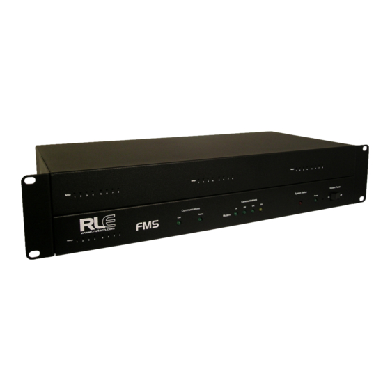
Falcon FMS
RLE Technologies Falcon FMS Manuals
Manuals and User Guides for RLE Technologies Falcon FMS. We have
1
RLE Technologies Falcon FMS manual available for free PDF download: User Manual
RLE Technologies Falcon FMS User Manual (196 pages)
Facilities Monitoring System
Brand:
RLE Technologies
| Category:
Measuring Instruments
| Size: 7 MB
Table of Contents
Table of Contents
5
System Overview
15
Product Description
15
Front Panel Indicators and Controls
16
System Overview
16
Figure 1.1 FMS 2U Front Panel Indicators and Controls
16
Terminal Block Designations
17
Figure 1.2 FMS Terminal Block Designations
17
System Overview
17
Table 1.1 Terminal Block Designations
17
Rear Panel Indicators
19
SW1 Switch Settings
19
Figure 1.3 Rear Panel Indicators
19
Figure 1.4 SW1-1 Switch and SW1-2 Switch
19
Getting Started
21
Installation
21
Falcon FMS Wiring
21
Power Supply and Ground Connections
21
Universal Input Connections
22
Figure 2.1 24VDC Power Supply Connection
22
Figure 2.2 48VDC Power Supply Connection
22
Figure 2.3 Universal Input Wiring Examples
23
Figure 2.4 Dry Contact Inputs with Common Ground
23
Relay 1 and 2 Connections
24
Figure 2.5 Relay Output Wiring Examples
24
Keypad Connection
25
COM2 Connection
25
Figure 2.6 Keypad Wiring
25
Figure 2.7 EIA-232 COM2 Connection
25
RJ11 Phone Line Connection
26
RJ45 Ethernet Connection
26
Figure 2.8 FMS Ethernet Connection to a PC Using a Crossover Cable
26
Figure 2.9 FMS Ethernet Connection to a PC on a Subnet
26
Modbus EIA-485 Connections
27
Figure 2.10 FMS EIA-485 Connection
27
Modbus EIA-232 Connections
28
Figure 2.11 FMS EIA-232 Connection to a DCE or DTE Device
28
Expansion Card a Connections
29
Figure 2.12 I/O Terminals for Expansion Card a
29
Figure 2.13 Analog Input Wiring for Expansion Card a
29
Figure 2.14 Dry Contact Inputs with Ground and Relay Outputs, Expansion Card a
30
Expansion Card C Connections
31
Figure 2.15 I/O Terminals for Expansion Card C
31
Figure 2.16 Typical Wiring for Expansion Card C
31
Communication
32
Set the FMS IP Address
32
Set the IP Address Using the ARP and PING Commands
32
Obtain the Ethernet Address (MAC Address)
32
Use the ARP Command
32
Use the PING Command
33
Troubleshooting the ARP/PING Commands
33
Set the IP Address Using a Web Browser
33
Set the FMS IP Address Using an EIA-232 Connection
34
FMS Web Interface
35
Main Menu/ Home Page
35
Figure 3.1 Example of a Configured FMS
35
Interface
35
Identity
36
Figure 3.2 Identity Menu
36
Table 3.1 Color Definitions
36
Configuration
37
Figure 3.3 Configuration Page
37
History
38
Alarm History
38
Figure 3.4 Alarm History Page
38
Table 3.2 Alarm History Log Entries
38
Event History
39
Digital Status History
39
Figure 3.5 Event History Page
39
Figure 3.6 Digital Status History Page
39
FMS Configuration
39
Keypad Access History
40
Web Access
40
Figure 3.7 Keypad Access History View
40
Figure 3.8 Web User Access Log
40
Data
41
Minute, Hour, and Day View
41
Figure 3.9 Data History Page
41
Data History Text Downloads
42
Figure 3.10 Minute Page
42
Figure 3.11 Data History Text Downloads Window
42
Alarm History Text (Alarmhistory.txt)
43
Graph
43
Figure 3.12 Alarm History Text Page
43
Figure 3.13 FMS Graph
43
Figure 3.14 Java Loading Image
44
Trends
45
Figure 3.15 Extended Trends Page
45
Trap Log
46
Relays
46
Figure 3.16 Example Trap Log
46
Figure 3.17 Example Relay Status Page
46
URL Links
47
Refresh
47
Figure 3.18 Example Still Images from IP Cameras
47
FMS Configuration
49
FMS Web Interface Overview
49
Figure 4.1 Initial Login for the FMS
50
Homepage and Configuration Menu
51
Figure 4.2 Top Bar on the FMS Home Page
51
Figure 4.3 FMS Configuration Menu
51
Inputs and Relays
52
Figure 4.4 FMS Input/Output Configuration Menu
52
Main Board Input Configuration (Channels 1-8)
53
Figure 4.5 FMS Main Board Input Configuration
53
Figure 4.6 Gain and Offset Calculator
54
Figure 4.7 NOI/NC Wiring Example
57
Expansion Card "A" Input Configuration
59
Figure 4.8 Expansion Card "A" Configuration Page
59
Expansion Card "C" Input Configuration
60
Internal Temperature and Internal Humidity Configuration (Optional)
60
Figure 4.9 Expansion Card "C" Configuration Page
60
Relay Configuration
61
Figure 4.10 Relay Configuration Page
61
Figure 4.11 Keypad/Relay Configuration
62
System
63
Figure 4.12 System Configuration Page
63
Figure 4.13 PDA Width Configuration
64
Alarm Management
65
Figure 4.14 Alarm Settings Menu
65
Trends
66
Figure 4.15 Trends Configuration Page
66
Figure 4.16 Trend Interval Chart
66
Clock
67
Schedules
67
Figure 4.17 Clock Configuration
67
Figure 4.18 Schedule Configuration
67
Battery/Supply Voltage
68
URL Links (1-5)
68
Figure 4.19 Battery Page
68
Figure 4.20 URL (1-5) Links Configuration
68
URL Links (6-10)
69
Links
69
Figure 4.21 URL (6-10) Links Configuration
69
Figure 4.22 Links Configuration Page
69
Nest/Egg
70
Falcon Nest Configuration
70
Figure 4.23 Nest/Egg Configuration Page
70
Figure 4.24 Nest Configuration
70
Egg Configuration
71
Figure 4.25 Egg Configuration
71
Modem/Phone Numbers
72
Figure 4.26 Modem Configuration
72
Configure Phone Numbers
73
Figure 4.27 Phone Number Configuration
73
Configure Phone Number 16 (PPP)
75
Keypad/Dtmf Access Users
75
Figure 4.28 Phone Number 16 (PPP) Configuration
75
Figure 4.29 Sample URL (6-10) Links Configuration
75
Internet Protocol
76
Figure 4.30 Sample IP Configuration Menu
76
User Administration (Web Access)
77
Figure 4.31 Web Access Configuration
77
Network Statistics
78
ICMP Ping
78
Figure 4.32 Network Statistics Page
78
Figure 4.33 ICMP Ping Page
78
Email/Dns
79
Figure 4.34 Email/Dns Configuration Page
79
Network Time Protocol
80
Figure 4.35 Network Time Protocol Configuration Page
80
Snmp/Syslog
81
Figure 4.36 SNMP Configuration Page
81
Bacnet
82
Figure 4.37 Bacnet Configuration Pages
82
Com Port1/Modbus/Snmp/Telnet
83
Figure 4.38 Com Port1/Modbus/Snmp/Telnet Configuration
83
Modbus/Snmp Slave Units
84
Figure 4.39 Modbus Generic Slave Unit Configuration
84
Figure 4.40 Modbus BCM 16-Unit Configuration Page
84
Pue/Dcie/Summary
85
Map
85
Figure 4.41 Modbus BCM 4-Unit Configuration Page
85
Flash Program
86
Product Registration
86
Figure 4.42 Flash Program Configuration Page
86
Communication
87
Modbus
87
Hardware Connections
87
Eia-232
87
Figure 5.1 FMS Modbus EIA-232 Connection to an EIA-232 DCE Device
88
Figure 5.2 FMS Modbus EIA-232 Connection to an EIA-232 DTE Device
88
Table 5.1 COM1 DB9 Male Pin out
88
Eia-485
89
Figure 5.3 EIA-485 Wiring Connections
89
Table 5.2 COM1 TB5 Pin out
89
Figure 5.4 EIA-485 Wiring to Rle/Veris Bcms (Branch Circuit Monitors)
90
Modbus/Snmp/Com1 Configuration (Modbus Master and Slave)
91
Figure 5.5 Example Modbus/Snmp/Com1 Configuration-Modbus Master
91
Modbus Slave Register Display Log
93
Figure 5.6 Modbus Slave Register Display Log
93
Table 5.3 Modbus Slave Register Display Log
94
Modbus Packet Log
95
Reset Modbus Port
95
Figure 5.7 Modbus Packet Log
95
Figure 5.8 Modbus Rest Port Confirmation
95
Table 5.4 Modbus Packet Log
95
Modbus Master Poll Data Log
96
Sms/Text Modem Log
96
Figure 5.9 Example Modbus Master Poll Data Log
96
Table 5.5 Modbus Master Poll Data Log
96
Configuring Inputs and Relays for Slave Units (Modbus, SNMP, or Bacnet)
97
Figure 5.10 Input and Relay Configuration Menu
97
Figure 5.11 Individual Input Configuration Screen
98
Modbus/Snmp Slave Units Configuration-Modbus Generic (Typical)
100
Figure 5.12 Modbus Slave Unit Configuration
100
Unit Number Links
101
Figure 5.13 Example Modbus Slave Unit
101
Modbus Register Links
103
Figure 5.14 Modbus Register Configuration Menu
103
Figure 5.15 Individual Modbus Configuration Screen
103
Read/Preset Single Register
105
Modbus/Slave Units Configuration - Modbus Master BCM - 4
105
Figure 5.16 Read/Preset Single Register Page
105
Figure 5.17 Modbus BCM-4 Unit Configuration
106
Unit Number Links
107
Figure 5.18 Individual Slave Configuration Screen
107
Modbus Register Links
108
Figure 5.19 Modbus Registers (BCM) Page
108
CB# Links
109
Figure 5.20 Circuit Breaker Configurations for Individual Bcms
109
Modbus/Slave Units Configuration - Modbus Master BCM - 16
110
Figure 5.21 Modbus BCM-16 Unit Configuration Page
110
Additional Modbus Information
111
Slave Register Map
111
Table 5.6 Slave Register Map
111
Alarm Bit Map (Reg 40201--40306)
112
Configuration Codes (Reg 40401-40504)
112
Table 5.7 Alarm Bit Map
112
Table 5.8 Configuration Codes
112
Bacnet Slave Units Configuration - Bacnet/Ip Master
113
Bacnet Configuration
114
Figure 5.22 Bacnet Configuration Page
114
Bacnet Slave Unit Configuration
115
Figure 5.23 Bacnet Unit Configuration
115
Unit Number Links
116
Figure 5.24 Individual Slave Unit Configuration Page
116
Figure 5.25 Bacnet Instance Configuration
116
Bacnet Instance Register Links
117
Telnet
117
Hardware Connections
117
Figure 5.26 Bacnet Configuration Registers Page
117
Table 5.9 COM1 DB9 Male Pin out
117
Figure 5.27 FMS Connection to an EIA-232 Device
118
Telnet/Com1 Configuration
119
Telnet Communication
119
Figure 5.28 COM Port1/Modbus/Snmp/Telnet Configuration Page
119
Figure 5.29 Telnet Communication, IP Address of 10.0.0.108, Port 3201
120
Figure 5.30 Example Telnet Connection Showing Specific Parameters
120
Pue/Dcie
121
Facility Power Monitoring
121
Figure 6.1 Pue/Dcie Data on FMS Home Page
121
Designating Pue/Dcie Data
122
Figure 6.2 Gather Modbus Register Information
122
Pue/Dcie
122
Figure 6.3 Enable Pue/Dcie and Designate Gauge Behavior
123
Figure 6.4 Designate Kw Gathering Devices
123
Pue/Dcie Trending
124
Format Trends
124
Figure 6.5 Data for Third Party Applications
124
View Trends
125
Figure 6.6 Establish Trending
125
Figure 6.7 View Your Trending Data
125
Figure 6.8 Trending Graph
125
Figure 6.9 CSV Data
126
Facility Mapping
127
FMS Mapping Feature
127
Figure 7.1 FMS Map
127
Upload the Map Image
128
Figure 7.2 Map Configuration Page
128
Figure 7.3 Map Image Upload Message
128
Map Inputs
129
Figure 7.4 Map Image Upload Error Message
129
Figure 7.5 FMS Mapping Crosshairs - Insertion Point
129
Map Analog and Digital Input Points
130
Figure 7.6 FMS Map Key
130
Figure 7.7 FMS Input/Output Configuration Menu
130
Figure 7.8 FMS Input Configuration Menu
130
Map Modbus and SMNP Slave Units
131
Figure 7.9 FMS Mapping Crosshairs - Insertion Point
131
Figure 7.10 Modbus/Snmp (Slave) Unit Configuration Screen
132
Figure 7.11 Mapping Point Insertion
132
Add a Link to the FMS Home Page
133
Back up the Map Data
133
Figure 7.12 Modbus / SNMP Slave Unit Detailed View
133
Facility Mapping
134
Interface
135
Unit Start up
135
Flash Executable Code
136
Main Menu
136
Table 8.1 EIA-232 Main Menu
136
Network Configuration - Netcfg
137
Bootloader Menu
137
Table 8.2 Main Configuration Menu Options (SC)
137
Table 8.3 IP Configuration Menu
138
Remote Access
139
Remote Access Configuration
139
Figure 9.1 FMS Dial-Up Menu
140
Remote Access
140
Point-To-Point Protocol
141
Configuring the FMS
141
Configuring the PC
142
Loading Firmware and Configuration Data
143
Loading FMS Firmware
143
Figure 11.1 Flash Program Configuration Page
144
Figure 11.2 Choosing a Firmware File
144
Figure 11.3 Firmware Load Messages
145
Figure 11.4 Current Firmware Version as Shown in FMS Interface
145
Loading Firmware Using TFTP Client
146
Updating FMS Firmware Via the EIA-232 COM2 Port (X-Modem)
146
Loading Firmware and Configuration Data
146
Loading and Saving FMS Configuration Data
147
Saving Configuration Data
147
Figure 11.5 Save Configuration File (Flash Program Configuration Page)
147
Loading Configuration Data
148
Figure 11.6 Load Configuration File (Flash Program Configuration Page)
148
FMS Expansion Cards
151
Expansion Card Descriptions
151
Table A.1 Expansion Card Descriptions
151
Expansion Card Installation
152
Installing an Expansion Card into a 2U FMS
152
Figure A.1 Back of 2U FMS Showing Hex Standoffs and Screws to Remove
152
Figure A.2 Side Plate ("Ear") with Two Mounting Screws Removed
152
AFMS Expansion Cards
152
Figure A.3 Sliding the Base and Cover Apart
153
Figure A.4 Two-Rack Unit Opened
153
Table A.2 SW2 DIP Switch Settings for Expansion Card Slots
153
Figure A.5 SW2 DIP Switches
154
Figure A.6 Expansion Card with Ribbon Cable Attached
155
Figure A.7 Expansion Card Mounting in a Two-Rack Unit
156
Figure A.8 Expansion Card Final Placement in a Two-Rack Unit
157
Installing an Expansion Card into a 1U FMS
158
Converting Current Input Channels to Voltage Input Channels on Expansion Card a
159
Figure A.9 Expansion Card Current Channel (4-20Ma) Configuration
159
Figure A.10 Expansion Card Voltage Channel (0-5V or 0-10V) Configuration
159
Analog Averaging
161
Analog Averaging Overview
161
How Analog Averaging Affects Values
161
B Analog Averaging
162
C Analog Input 4-20Ma Reference Chart
163
Table C.1 Analog Input 4-20Ma Reference Chart
163
C Analog Input 4-20Ma Reference Chart
164
FMS Accessories Wiring
165
Figure D.1 T120 and T120D Temperature Sensors
165
Figure D.2 TH140 and TH140D Temperature/Humidity Sensors
165
Figure D.3 Dwyer Temperature/Humidity Sensor
166
Figure D.4 BAPI Temperature/Humidity Sensor
166
Figure D.5 HD150, HD150-2, CM150-2, and HG150-2 Gas Sensors
166
DFMS Accessories Wiring
166
Figure D.6 RD150-F2, RD150-2 & RD150-R Refrigerant Detectors
167
Figure D.7 PFM Power Fail Monitor
167
Figure D.8 Seahawk LD5100 Distance Read Leak Detection System (Dry Contact)
168
Configuring the Seahawk LD5100 as an Analog Input
169
Figure D.9 Seahawk LD5100 Distance Read Leak Detection System (4-20Ma)
169
Figure D.10 Seahawk LD1000, LD300 Leak Detection Systems
169
Wiring for Other Falcon FMS Accessories
170
Figure D.11 Seahawk LD1000, LD300, and LDRA6 Zone Leak Detection Systems
170
Alarm ID Reference Tables
171
Analog Tables
171
Table E.2 Analog Alarm Reference Table - Input Slots 1 and 2
173
Table E.3 Analog Alarm Reference Table - Input Slots 3 and 4
174
Digital Tables
175
FFMS Slot Designations
179
Input Slot Designation Table
179
Table F.1 Input Slot Designation Table - Slot 0
179
Table F.2 Input Slot Designation Table - Slot 1
180
Table F.3 Input Slot Designation Table - Slot 2
181
Table F.4 Input Slot Designation Table - Slot 3
181
Table F.5 Input Slot Designation Table - Slot 4
182
Output Slot Designation Table
183
Relay Control Logic
185
Falcon-EM Relay Logic
185
Figure G.1 FMS Relay Control Logic Diagram
187
Figure H.1 Snmp/Syslog Configuration Page
189
HSNMP V3
190
Table H.1SNMP V3 Trap Settings
190
Table H.2Trap Destination Settings
190
Table H.3SNMP V3 Profile Settings
191
Table I.1 Technical Specifications
193
I Technical Specifications
194
Advertisement
Advertisement
Related Products
RLE Technologies Falcon Wi-MGR
RLE Technologies F1000
RLE Technologies F3400
RLE Technologies MONITORING F110
RLE Technologies FDS-Wi
RLE Technologies LD5100
RLE Technologies WiNG-MGR
RLE Technologies WiNG-MGR v2
RLE Technologies WiNG-RXT
RLE Technologies Categories
Measuring Instruments
Controller
Security Sensors
Gateway
Temperature Controller
More RLE Technologies Manuals
Login
Sign In
OR
Sign in with Facebook
Sign in with Google
Upload manual
Upload from disk
Upload from URL