Table of Contents
Advertisement
Trademarks
FOXWELL is trademark of Shenzhen Foxwell Technology Co., Ltd.
All other marks are trademarks or registered trademarks of their respective
holders.
Copyright Information
©2022 Shenzhen Foxwell Technology Co., Ltd.
All rights reserved.
Disclaimer
The information, specifications and illustrations in this manual are based on the
latest information available at the time of printing.
Foxwell reserves the right to make changes at any time without notice.
Visit our website at
www.foxwelltech.us
For Technical Assistance, send us email at
support@foxwelltech.com
1
Automotive Diagnostic System NT809BT User's Manual V1.0
Advertisement
Table of Contents

Related Manuals for Foxwell NT809BT


Summary of Contents for Foxwell NT809BT
- Page 1 Disclaimer The information, specifications and illustrations in this manual are based on the latest information available at the time of printing. Foxwell reserves the right to make changes at any time without notice. Visit our website at www.foxwelltech.us For Technical Assistance, send us email at support@foxwelltech.com...
-
Page 2: One-Year Limited Warranty
FOXWELL. 3 The customer shall bear the cost of shipping the product to FOXWELL. And FOXWELL shall bear the cost of shipping the product back to the customer after the completion of service under this limited warranty. - Page 3 The customer will be billed for any parts or labor charges not covered by this limited warranty. d) FOXWELL will repair the Product under the limited warranty within 30 days after receipt of the product. If FOXWELL cannot perform repairs covered...
- Page 4 (the Consumer). This limited warranty gives the Consumer specific legal rights and the Consumer may also have other rights which vary from state to state. Automotive Diagnostic System NT809BT User's Manual V1.0...
-
Page 5: Safety Information
● Fuel, oil vapors, hot steam, hot toxic exhaust gases, acid, refrigerant and other debris produced by a malfunction engine can cause serious injury or death. Do not use the tool in areas where explosive vapor may collect, Automotive Diagnostic System NT809BT User's Manual V1.0... - Page 6 ● Block drive wheels before testing with engine running. Put the transmission in park (for automatic transmission) or neutral (for manual transmission). And never leave a running engine unattended. ● Do not wear jewelry or loose fitting clothing when working on engine. Automotive Diagnostic System NT809BT User's Manual V1.0...
-
Page 7: Table Of Contents
ALIBRATION 6.7 C (CVT) ................41 ONTINUOUS ARIABLE RANSMISSION 6.8 G ........................41 EARNING 6.9 T ..............41 RESSURE ONITORING YSTEM ROGRAMMING 6.10 I ........................41 NJECTOR ODING 6.11 ABS B ........................41 LEEDING Automotive Diagnostic System NT809BT User's Manual V1.0... - Page 8 YSTEM ETTINGS 12.8 G ..........................63 ENERAL 12.9 U ....................63 NINSTALL EHICLE OFTWARE 12.10 C ........................64 LEAR APP DATA 12.11 P ........................64 RINT ETTINGS 12.12 A ...........................67 BOUT 13 REMOTE SUPPORT ........................67 Automotive Diagnostic System NT809BT User's Manual V1.0...
-
Page 9: Using This Manual
Bold text is used to highlight selectable items such as buttons and menu options. Example: Select Diagnostic from the Home screen of the NT809BT application. 1.2 Symbols and Icons 1.2.1 Solid Spot Operation tips and lists that apply to specific tool are introduced by a solid spot ●. -
Page 10: Introduction
Do not soak scanner as water might find its way into the scanner. 2 Introduction The brand new Android scan tool NT809BT inherits the same Foxwell advantages in car fault diagnostic tech, such as multi manufacturer coverage, service functions and accurate test data, making it the perfect tool for busy garages or workshops, who need the latest technology at unbeatable value. -
Page 11: Vci Dongle Descriptions
Do not use solvents such as alcohol to clean display. Use a mild nonabrasive detergent and a soft cotton cloth. 2.2 VCI Dongle Descriptions NT809BT connects to the vehicle and get data through the VCI dongle either by Bluetooth or USB communication. Automotive Diagnostic System NT809BT User's Manual V1.0... -
Page 12: Accessories
3 Power Light - turns to red when powered on. 2.3 Accessories This section lists the accessories that go with the scanner. If you find any of the following items missing from your package, contact your local dealer for assistance. Automotive Diagnostic System NT809BT User's Manual V1.0... -
Page 13: Technical Specifications
ISO9141-2, ISO14230-2, ISO15765-4, K/L lines, Double K Line SAE-J1850 VPW,SAE-J1850PWM,CAN ISO 11898, High-speed, Protocols Middle-speed, Lows-peed and Single wire CAN, KW81, KW82, GM UART, UART Echo Byte Protocol, Honda Diag-H Protocol, TP2.0, TP1.6, SAE J1939, SAE J1939, SAE J1708,Fault-Tolerant Automotive Diagnostic System NT809BT User's Manual V1.0... -
Page 14: Getting Started
3.1 Powering up the Scanner Before using the NT809BT applications (including updating the scanner), please make sure to provide power to the scanner. The unit operates on any of the following sources: Internal Battery Pack ●... -
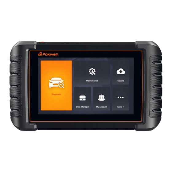
Page 15: Screen Layout Of Home Screen
Maintenance - leads to screens for common used special functions like ● Oil light reset, EPB, BRT, and DPF etc. Update - leads to screens for Foxwell ID registration and updating the ● scanner. Data Manager - leads to screens for saved screenshots, pictures and test ●... - Page 16 VCI Manager – VCI manage (VCI binding, unbinding, rescan vehicle ● software). 3.3.2 Diagnostic Menu Touch Diagnostic at the NT809BT application menu, and the Diagnostic menu will display. The operations of the buttons of Diagnostic menu are described in the below table. Figure 3-3 Sample Diagnostic Menu Screen...
-
Page 17: Vehicle Identification
The working range for Bluetooth communication is about 10-20m, providing easy connection to vehicles in any location throughout the shop. Figure 4-1 Sample Communication Screen 3. The VCI dongle will connect to the tablet automatically. Automotive Diagnostic System NT809BT User's Manual V1.0... -
Page 18: Vin Reading
4.2 VIN Reading VIN button on the title bar is a shortcut for VIN reading menu, which includes Automatic Read, Manual Entry, eliminating the need for navigating through complicated car identification process. Automotive Diagnostic System NT809BT User's Manual V1.0... - Page 19 (VIN). To identify a vehicle by Automatic Read: 1. Select Diagnostic from home screen of the NT809BT application. 2. Click VIN and choose Automatic Read from the option list. 3. When the scan tool builds connection with the vehicle, the VIN number displays.
-
Page 20: Manual Selection
Manual Entry allows to identify a vehicle by inputting VIN manually. To identify a vehicle by Manual Entry: 1. Select Diagnostic from home screen of the NT809BT application. 2. Click VIN and choose Manual Entry from the option list. 3. Press Keyboard button to input a valid VIN code and press OK to continue. - Page 21 (VIN). To identify a vehicle by Smart VIN: 1. Select Diagnostic from home screen of the NT809BT application. 2. A screen with vehicle manufacturers displays. Select the area where the vehicle manufacturer from. A menu of all vehicle manufacturers displays.
- Page 22 VIN characters, such as model year, and engine type. To identify a vehicle by manual vehicle selection: 1. Select Diagnostic from home screen of the NT809BT application. 2. A screen with vehicle manufacturers displays. Select the area where the vehicle manufacturer is from.
-
Page 23: Vehicle History
To identify a vehicle by Vehicle History: 1. Select Diagnostic from home screen of the NT809BT application. 2. Select History button at the top of the diagnostic page and the diagnostic records will display. -
Page 24: Vehicle Identification
(DTCs) overview. Depending on the number of control modules, it may take a few minutes to complete the test. To perform an automatic system scan: 1. Press Quick Scan option to start. 2. To pause the scan, press the Pause button on the screen. Automotive Diagnostic System NT809BT User's Manual V1.0... - Page 25 4. Press Report to create an overview of installed control units and their system status, or press Save to save the report. Press Erase to clear the information. Figure 5-4 Sample DTC Save Screen Automotive Diagnostic System NT809BT User's Manual V1.0...
- Page 26 Control Modules displays all controllers available of the vehicle manufacturer. The controllers listed on the menu do not mean that they are installed on the vehicle. It is useful for technicians who are familiar with the vehicle specifications. Automotive Diagnostic System NT809BT User's Manual V1.0...
-
Page 27: Diagnostic Operations
● Live Data ● ECU Information ● NOTE Not all function options listed above are applicable to all vehicles. Available options may vary by the year, model, and make of the test vehicle. Automotive Diagnostic System NT809BT User's Manual V1.0... - Page 28 DTC set. It is a good function to help determine what caused the fault. Automotive Diagnostic System NT809BT User's Manual V1.0...
- Page 29 To clear codes, make sure that the ignition key is switched to ON with the ● engine off. Clear Codes does not fix the problem that caused the fault! DTCs should ● only be erased after correcting the condition(s) that caused them. To clear codes: Automotive Diagnostic System NT809BT User's Manual V1.0...
- Page 30 All Data menu lets you view all live PID data from a selected control module. To view all live PID data: 1. Press Select ALL for select all live PID data and press Deselect ALL to deselect all items. Automotive Diagnostic System NT809BT User's Manual V1.0...
- Page 31 2. Press OK to complete the selection and all readings will be displayed in text format by default. Figure 5-16 Sample Live Data Selection Screen Figure 5-17 Sample Live Data Screen Name Description Help To provide help information of a PID Automotive Diagnostic System NT809BT User's Manual V1.0...
- Page 32 Figure 5-19 Sample Live Data Screen 3. Swipe the screen up and down to view additional information when necessary. Automotive Diagnostic System NT809BT User's Manual V1.0...
- Page 33 Merge Graph: merges multiple PID plots into one coordinate, so you can ● easily see how they affect each other, providing you with the most comprehensive and functional look at live data possible. Automotive Diagnostic System NT809BT User's Manual V1.0...
- Page 34 3. To deselect an item, tap the line again. Alternatively, tap SELECT ALL or Deselect ALL to select or deselect all items at once. 4. Press OK to complete the selection, and all selected items display. Automotive Diagnostic System NT809BT User's Manual V1.0...
- Page 35 1. Press Record button to record all selected live data, then it will show the record time and frames. Figure 5-25 Sample Live Data Record Screen 2. Press Stop button to create a record, then press OK to save the record into Data Playback of Data Manager. Automotive Diagnostic System NT809BT User's Manual V1.0...
- Page 36 Figure 5-28 Sample ECU Information Screen Press to print the information if need be. Press to exit. 4. Press Save to store ECU information screen and Press OK to complete save or Press Cancel to give up. Automotive Diagnostic System NT809BT User's Manual V1.0...
-
Page 37: Maintenance
The Service Indicator System is designed to alert the driver when the vehicle is due for a service. Oil service reset methods are determined by the vehicle being tested. Depending on the vehicle being tested, any of the following means displays: Automotive Diagnostic System NT809BT User's Manual V1.0... -
Page 38: Electronic Parking Brake (Epb) Service
Mercedes SBC vehicles - allows to change brake fluid/bleed brake system. Perform service reset and service position on BMW EPB vehicles - ● allows to do the CBS reset and CBS correction for front brake and rear brake. Automotive Diagnostic System NT809BT User's Manual V1.0... -
Page 39: Battery Replacement (Brt)
1. Replace the old battery with the new one. Ensure the key is not in the ignition. 2. Connect the scanner to the vehicle’s 16 pin Data Link Connector (DLC) with the diagnostic cable. Automotive Diagnostic System NT809BT User's Manual V1.0... -
Page 40: Diesel Particulate Filter (Dpf) Regeneration
SAS Calibration menu lets you perform calibration of the Steering Angle Sensor, which permanently stores the current steering wheel position as straight-ahead in the sensor EEPROM. On successful calibration of the sensor, its fault memory is automatically cleared. Automotive Diagnostic System NT809BT User's Manual V1.0... -
Page 41: Continuous Variable Transmission (Cvt)
Air is compressible, so when the brakes are applied any air bubbles in the system must first be compressed before the hydraulic fluid will transmit pressure to apply the brakes. Automotive Diagnostic System NT809BT User's Manual V1.0... -
Page 42: Key Programming/Immobilizer
7.1 Image Image option leads to screens for review of stored screenshots. In case a failure of NT809BT application or the Android system occurs, please just take a screenshot and send it to our team to help with the troubleshooting. - Page 43 Figure 7-3 Sample Screenshot Screen 2. Add a description of the image, and press the OK to save, cancel button to give up. Figure 7-4 Sample Screenshot Screen Automotive Diagnostic System NT809BT User's Manual V1.0...
- Page 44 7.1.2 Review Image To review the screenshots: 1. Press Data Manager from home screen of NT809BT diagnostic application. 2. Press Image and all available pictures will be displayed. 3. Press Diagnostic Screenshot for application menu screenshot or Press System Screenshot for system menu screenshot, then all available pictures will be displayed.
-
Page 45: Pdf Report
PDF icon on the test screen, add a description and press OK button to save. 7.2.1 How to Create a PDF Report To create a PDF report: 1. Press Data Manager from home screen of NT809BT diagnostic application. 2. Press Report from Data Manager. 3. Press any reports saved. - Page 46 Figure 7-10 Sample of Report edit Screen 7.2.2 Review PDF Report To review the PDF reports: 1. Press Data Manager from home screen of NT809BT diagnostic application. 2. Press PDF and all available PDF files will be displayed. Figure 7-11 Sample Browse PDF Screen...
-
Page 47: Data Playback
Playback speed and direction (forward or reverse) can also be controlled. To review recorded live data: 1. Press Data Manager from home screen of NT809BT diagnostic application. 2. Press Data Playback and all available records display. - Page 48 5. To move forward or reverse back of the playing, just drag the progress bar forward or reverse. Press the button to stop. 6. Long press the record to Rename or Delete the records. Figure 7-16 Sample Edit Data Playback Screen Automotive Diagnostic System NT809BT User's Manual V1.0...
-
Page 49: My Account
Feedback and Suggestions ● Figure 8-1 Sample My Account Screen 8.1 Registration If you are new to FOXWELL, please register a FOXWELL ID first either by Registering with the built-in client; ● Or registering through our website with the URL: ●... - Page 50 Figure 8-2 Sample Update Client Main Screen 2. Enter the User Name (use one of your existing mail addresses as user name), and press Send Code button for get a verification code, Foxwell will send a 4-digit verification code to the email you just entered.
- Page 51 Figure 8-6 Sample Production Activation Screen 8.1.2 Register through Website To register through our website: 1. Visit Foxwell official website www.foxwelltech.us and press Register icon, or go to the registration page by selecting Support from home page and then click Register.
- Page 52 Free Registration to complete. Figure 8-9 Sample Create Account Screen 3. Sign in to the Member Center, click New Registration, input the right serial number and click Submit to activate the product. Automotive Diagnostic System NT809BT User's Manual V1.0...
-
Page 53: Sign In
Figure 8-10 Sample Product Register Screen 8.2 Sign in Press My Account or Update from home screen of NT809BT diagnostic application, the user login page will show, enter your FOXWELL ID and password, and press Sign in button to sign in. - Page 54 2.Click Submit to continue the activation and press to give up activation. Figure 8-13 Sample Product Activation Submit Screen 3. “Product is activated successfully” message will appear if activate successfully. Figure 8-14 Sample activate success Screen Automotive Diagnostic System NT809BT User's Manual V1.0...
-
Page 55: M Yaccount
This option allows you to log on your e-mail and send feedback and suggestions about Foxwell products. NOTE Please download e-mail client on the NT809BT before using this function. To send feedback and suggestions about Foxwell products: Automotive Diagnostic System NT809BT User's Manual V1.0... - Page 56 1. Press My Account from home screen of the NT809BT diagnostic application. 2. Press Feedback and Suggestions option to show Feedback page, there are two options--Diagnosis Feedback and General Feedback. Figure 8-17 Sample feedback record Screen 3. Select Diagnosis Feedback or General Feedback for creating a feedback.
-
Page 57: Update
The scanner can be updated to keep you stay current with the latest development of diagnosis. This section illustrates how to register and update your scan tool. You can register both on Foxwell website or by the built-in update client. -
Page 58: Manual Update
2. Select Automatic Update, then set automatic update notice enable. 9.2 Manual Update To update the diagnostic application: 1. Press Update of NT809BT diagnostic application, and the update client starts up automatically. 2. The available updates display. Click the check box(s) in front of the software you wish to update and then click the Update button to download. - Page 59 VCI. When clicking OK, it will execute unbind, rebind, and refresh the vehicle. Figure 10-1 Sample Unbind a VCI dongle Figure 10-2 Sample Unbinding Confirmation Prompt Figure 10-3 Sample Unbinding Current VCI Automotive Diagnostic System NT809BT User's Manual V1.0...
-
Page 60: Firmware Update
4. Check the battery level to ensure that the battery level should be greater than 20%. 5. It will start update automatically if there is an update available. If update failed, please follow the on-screen instructions to troubleshoot and repeat the update. Automotive Diagnostic System NT809BT User's Manual V1.0... -
Page 61: Settings
When Settings application is selected, a menu with available service options displays. Menu options typically include: ● Unit ● Language ● Font Size ● Sort Tiles ● Remote control ● Automatic Update ● System Settings Automotive Diagnostic System NT809BT User's Manual V1.0... -
Page 62: Units
Selecting Unit opens a dialog box that allows you to choose between Imperial customary or metric units of measure. To change the unit setup: 1. Press Settings from home screen of the NT809BT diagnostic application. 2. Press Unit and available unit system display. 3. Select a unit system. -
Page 63: Remote Control
This option allows you to select a tool of remote control. There are two remote tools available TeamViewer QuickSupport or AnyDesk. To change remote control 1. Press Settings from home screen of the NT809BT diagnostic application, then select Remote control. 2. Select your preferred tool. -
Page 64: Clear App Data
This option allows you to print any data or information anywhere and anytime either via PC network or Wi-Fi. To setup the printer connection: 1. Tap the Settings application on home screen of NT809BT. 2. Tap the Printing Settings option on the option list. Automotive Diagnostic System NT809BT User's Manual V1.0... - Page 65 Figure 12-3 Sample Print Settings Screen 3. Tap Print Plugin Manager and turn on the Mopria Print Service, then NT809BT will search for available printers automatically. Figure 12-4 Sample Print Service Manager Screen 4. Select Mopria Print Service. Press for return.
- Page 66 Click the blue marked part to make more settings for the printer, such as paper size, number of copies, etc. Figure 12-8 Sample of File Printing Screen NOTE Automotive Diagnostic System NT809BT User's Manual V1.0...
-
Page 67: About
About how to set the tool of default, please refer to 10.5 Remote control. TeamViewer QuickSupport To use QuickSupport for to remote control: 1. Click the Remote Control icon on the main menu of the NT809BT to start TeamViewer QuickSupport. Press for return. - Page 68 Figure 13-1 Sample QuickSupport Screen 2. Send your ID to us to let our team to take control your tablet. Automotive Diagnostic System NT809BT User's Manual V1.0...
Need help?
Do you have a question about the NT809BT and is the answer not in the manual?
Questions and answers
Why doesnt ant of the maintenance functions woek?