Table of Contents
Advertisement
Trademarks
FOXWELL is trademark of Shenzhen Foxwell Technology Co., Ltd.
All other marks are trademarks or registered trademarks of their respective holders.
Copyright Information
© 2013 Shenzhen Foxwell Technology Co., Ltd.
All rights reserved.
Disclaimer
The information, specifications and illustrations in this manual are based on the latest information
available at the time of printing.
Foxwell reserves the right to make changes at any time without notice.
Visit our website at:
www.foxwelltech.com
For Technical Assistance, send us email at
support@foxwelltech.com
1
AutoMaster Pro Manual_English_V1.01
Advertisement
Table of Contents

Subscribe to Our Youtube Channel
Related Manuals for Foxwell Auto Master Pro


Summary of Contents for Foxwell Auto Master Pro
- Page 1 Disclaimer The information, specifications and illustrations in this manual are based on the latest information available at the time of printing. Foxwell reserves the right to make changes at any time without notice. Visit our website at: www.foxwelltech.com For Technical Assistance, send us email at support@foxwelltech.com...
-
Page 2: One-Year Limited Warranty
The customer will be billed for any parts or labor charges not covered by this limited warranty. d) FOXWELL will repair the Product under the limited warranty within 30 days after receipt of the product. If FOXWELL cannot perform repairs covered under this limited warranty within 30 days,... - Page 3 OF THE PRODUCT OR ARISING FROM BREACH OF THE WARRANTY, BREACH OF CONTRACT, NEGLIGENCE, STRICT TORT, OR ANY OTHER LEGAL OR EQUITABLE THEORY, EVEN IF FOXWELL KNEW OF THE LIKELIHOOD OF SUCH DAMAGES. FOXWELL SHALL NOT BE LIABLE FOR DELAY IN RENDERING SERVICE UNDER THE LIMITED WARRANTY, OR LOSS OF USE DURING THE PERIOD THAT THE PRODUCT IS BEING REPAIRED.
-
Page 4: Safety Information
Safety Information For your own safety and the safety of others, and to prevent damage to the equipment and vehicles, read this manual thoroughly before operating your scanner. The safety messages presented below and throughout this user’s manual are reminders to the operator to exercise extreme care when using this device. -
Page 5: Table Of Contents
Block drive wheels before testing with engine running. Put the transmission in park (for ● automatic transmission) or neutral (for manual transmission). And never leave a running engine unattended. Do not wear jewelry or loose fitting clothing when working on engine. ●... - Page 6 4.3.2 Freeze Frame Data..........................21 4.3.3 Erase Codes............................. 21 4.3.4 ECU Information..........................22 4.3.5 Live Data............................23 4.3.5.1 Complete Data List........................23 4.3.5.2 Custom Data List...........................25 5 OBDII/EOBD OPERATIONS...........................26 5.1 S ............................27 YSTEM TATUS 5.2 R .............................. 28 ODES 5.3 E .............................29 RASE ODES...
-
Page 7: Using This Manual
1 Using This Manual We provide tool usage instructions in this manual. Below is the conventions we used in the manual. 1.1 Bold Text Bold text is used to highlight selectable items such as buttons and menu options. Example: Press the ENTER button to select. 1.2 Symbols and Icons 1.2.1 Solid Spot Operation tips and lists that apply to specific tool are introduced by a solid spot ●. -
Page 8: Introduction
Do not soak keypad as water might find its way into the scanner. 2 Introduction AUTOMASTER PRO series scanners from Foxwell are innovative diagnostic tools for most vehicles on the road today. With the tool properly connected to the vehicle’s data link connector (DLC), you can use the scanner to read diagnostic trouble codes and view “live”... -
Page 9: Accessory Descriptions
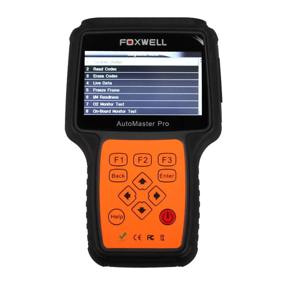
4 Direction Keys - select an option or scroll through a screen of data or text. 5 ENTER Key – executes a selected option and generally goes to the next screen. 6 BACK Key – exits a screen and generally returns to previous screen. 7 HELP Key –... -
Page 10: Connecting To Personal Computer With Usb Cable
3.1.1 Connecting to Vehicle Power The scanner normally powers on whenever it is connected to the data link connector (DLC). To connect to vehicle power: 1. Locate the data link connector (DLC). The DLC is generally located under the dash on the driver side of the vehicle. -
Page 11: Input Diaglog Box
Figure 3-1 Sample Home Screen 3.3 Input Dialog Box This section illustrates how to use the scan tool to input letters and numbers, such as VIN number, channel number, test values and DTC number. Typically, you may be required to input letters or numbers when you are doing any of the following operations. -
Page 12: Diagnostic Operations
Figure 3-3 Sample Numeric Keyboard Screen 3. To delete a letter or number, use the function key Previous to move the cursor to it and then press the Backspace button. 4. When finished the entry, press Finish key to continue. 4 Diagnostic Operations This section illustrates how to use the scanner to read and clear diagnostic trouble codes, and view “live”... - Page 13 2. A screen with vehicle manufacturer areas displays. Select the area where the vehicle manufacturer is from. A menu of all vehicle manufacturers from this area displays. Figure 4-2 Sample Vehicle Manufacturer Area Selection Screen 3. Select the vehicle manufacturer. A list of vehicle identification options displays. Figure 4-3 Sample Vehicle Manufacturer Selection Screen 4.
-
Page 14: Manual Vin Entry
Figure 4-5 Sample VIN Automatic Acquisition 6. Answer YES if the Vehicle Specification or VIN code is correct and a menu of controller selection displays. Answer NO if it is incorrect, and you are required to enter the correct VIN number manually. -
Page 15: Manual Vehicle Selection
Figure 4-8 Sample Manual VIN Entry with Keyboard 3. Input a valid VIN code and use the function key Finish to confirm. The scan tool starts to identify the vehicle. 4.1.3 Manual Vehicle Selection Manual Vehicle Selection identifies a vehicle by making several selections according to certain VIN characters, such as model year, and engine type. - Page 16 Figure 4-9 Sample System Menu Screen 2. When the test finished, press the function key Save on the screen, and a screen with a QWERTY keyboard displays. Figure 4-10 Sample Save Vehicle Record Screen 3. Enter a unique name for this vehicle and save it, and you will see this new vehicle in Vehicle Data Recorder menu.
-
Page 17: System Selection
Figure 4-12 Sample tested vehicle identification screen 2. Select the vehicle under test and press the ENTER key. 4.2 System Selection When you have completed the identification of vehicle, a menu for selecting system to test displays. Menu options typically include: Auto Scan ●... -
Page 18: Control Unit
Figure 4-15 Sample auto scan screen 4. If there is diagnostic trouble code(s) detected in a control unit, press the function key corresponding with Display DTC on the screen to view details of code information, and press the function key Quick Erase to clear them. Figure 4-16 Sample Display DTC screen 5. -
Page 19: Diagnostic Function Selection
Figure 4-17 Sample Function Menu screen 4.2.2 Control Unit Control Unit screen displays all controllers available of the vehicle manufacturer. The controllers listed on the menu do not mean that they are installed on the vehicle. To select a system for testing: 1. - Page 20 NOTE Not all function options listed above are applicable to all vehicles. Available options may vary by the year, model, and make of the test vehicle. A “The selected mode is not supported!” message displays if the option is not applicable to the vehicle under test. 4.3.1 Read Codes Read Codes menu lets you read trouble codes found in the control unit.
-
Page 21: Freeze Frame Data
Figure 4.21 Sample Code Screen 3. Press function key Save to store DTC information. Or use the BACK key to exit. 4.3.2 Freeze Frame Data Freeze Frame Data menu displays freeze frame data, a snapshot of critical vehicle operating conditions automatically recorded by the on-board computer at the time of the DTC set. It is a good function to help determine what caused the fault. -
Page 22: Ecu Information
NOTE To clear codes, make sure that the ignition key is switched to ON with the engine off. ● Erase Codes does not fix the problem that caused the fault! DTCs should only be erased after ● correcting the condition(s) that caused them. To clear codes: 1. -
Page 23: Live Data
Figure 4-25 Sample Function Menu Screen 2. A screen with detailed information of the selected control module displays. Figure 4-26 Sample ECU Information Screen 3. Press function key Save to store ECU information. Or use the BACK key to exit. 4.3.5 Live Data Live Data menu lets you view and record real time PID data from a selected vehicle electronic control module. - Page 24 Figure 4-27 Sample Live Data Selection Screen 2. Select the Complete List from the menu and press the ENTER key to display the datastream screen. Figure 4-28 Sample Complete List Screen 3. Scroll with the up and down arrow keys to highlight a line, if the One Graphic on the bottom is highlighted, it indicates the graphing is available for the selected line.
-
Page 25: Custom Data List
Figure 4-30 Sample Two PID Graph Screen 5. Press the function key Merge Graph to display two PID plots in one coordinate for easy and intuitive diagnosis. Figure 4-31 Sample Merged PID Plots Screen 6. To record the data to memory of the scanner, use the function key SAVE, and press Stop Saving to stop recording at any time. -
Page 26: Obdii/Eobd Operations
Figure 4-33 Sample Custom List Selection Screen NOTE To deselect an item, select it again and then press the ENTER key. Alternatively, use the function keys SELECT ALL and CLEAR ALL to select or deselect all items at once. 3. When finished selection, use the function key VIEW DATA to display selected items. Figure 4-34 Sample Datastream Screen 5 OBDII/EOBD Operations OBD-II/EOBD menu lets you access all OBD service modes. -
Page 27: System Status
Service $04 - clear/reset emission-related diagnostic information ● Service $05 - request oxygen sensor monitoring test results ● Service $06 - request on-board monitoring test results for specific monitored systems ● Service $07 - request emission-related diagnostic trouble codes detected during current or ●... -
Page 28: Read Codes
Figure 5-2 Sample System Status Screen 5.2 Read Codes Read Codes menu lets you read both stored codes and pending codes found in the control unit. Typical menu options include: Stored Codes ● Pending Codes ● Diagnostic trouble codes stored in a control module are used to help identify the cause of a trouble or troubles with a vehicle. -
Page 29: Erase Codes
Figure 5-4 Sample Read Codes Screen If no DTCs are present the message “No (Pending) Codes Found!” is displayed. If any manufacturer specific or enhanced codes detected, select vehicle a make before viewing DTC information. Figure 5-5 Sample No Codes Screen 3. -
Page 30: Live Data
NOTE To clear codes, make sure that the ignition key is switched to ON with the engine off. ● Erase Codes does not fix the problem that caused the fault! DTCs should only be erased after ● correcting the condition(s) that caused them. To clear codes: 1. - Page 31 Custom Data List ● 5.4.1 Complete Data List Complete Data List menu lets you view all live PID data from a selected system. To view all live PID data: 1. Scroll with the arrow keys to highlight Live Data from Diagnostic Menu and press the ENTER key.
- Page 32 Figure 5-11 Sample Complete List Screen 4. Scroll with the up and down arrow keys to highlight a line, if the One Graphic on the bottom is highlighted, it indicates the graphing is available for the selected line. Press the function key One Graphic to display the PID graph.
-
Page 33: Custom Data List
Figure 5-14 Sample Merge Graph Screen 7. To record the data to memory of the scanner, use the function key SAVE, and press Stop Saving to stop recording at any time. 8. Select Text to return to text viewing of PID data. 9. -
Page 34: Freeze Frame
To deselect an item, select it again and then press the ENTER key. Alternatively, use the function keys SELECT ALL and CLEAR ALL to select or deselect all items at once. 3. When finished selection, use the function key VIEW DATA to display selected items. Figure 5-17 Sample Datastream Screen 5.5 Freeze Frame Freeze Frame menu displays freeze frame data, a snapshot of critical vehicle operating... -
Page 35: Read I/M Readiness Status Data
2. Use the up and down arrow keys to scroll through data to select lines, and left and right arrow keys to scroll back and forth through different screens of data. If no freeze frame detected, the message “No freeze frame data stored!” is displayed. Figure 5-19 Sample Freeze Data Screen 3. - Page 36 To review I/M Readiness status, make sure that the ignition key is switched to ON with the ● engine off. Not all monitors are supported by all vehicles. ● To retrieve I/M Readiness Status data: 1. Scroll with the arrow keys to highlight I/M Readiness from Diagnostic Menu and press the ENTER key.
-
Page 37: O2 Monitor Test
Figure 5-22 Sample IM readiness screen 2 3. Press the BACK key to exit. 5.7 O2 Monitor Test OBD II regulations require certain vehicles monitor and test oxygen (O2) sensors to isolate fuel and emissions related faults. The O2 Monitor Test function is used to retrieve completed O2 sensors monitor test results. -
Page 38: On-Board Monitor Test
Figure 5-24 Sample O2 Monitor Test screen 3. Use the up and down arrow keys to scroll through data to select lines, and left and right arrow keys to scroll back and forth through different screens of data. Figure 5-25 Sample O2 Bank1 Sensor 1 Screen 4. - Page 39 for emission-related powertrain components and systems that are and are not continuously monitored. It is vehicle manufacturer who is responsible for assigning test and component IDs. NOTE Test results do not necessarily indicate a faulty component or system. To request on-board monitor test results: 1.
-
Page 40: Component Test
Figure 5-29 Sample CAN vehicle test screen 3. Scroll with the arrow keys to highlight a test group and press the ENTER key to confirm. A screen with details of the selected sensor displays. Use the up and down arrow keys to scroll through data to select lines, and left and right arrow keys to scroll back and forth through different screens of data. - Page 41 NOTE Some manufacturers do not allow tools to control vehicle systems. ● The manufacturer sets the criteria to automatically stop test. Refer to appropriate vehicle service ● manual before using this function. To perform a component test: 1. Scroll with the arrow keys to highlight Component Test from Diagnostic Menu and press the ENTER key.
-
Page 42: Request Vehicle Information
5.10 Request Vehicle Information Vehicle Information allows to request the vehicle’s VIN number, calibration ID(s) which identifies software version in vehicle control module(s), calibration verification numbers (CVN(s)) and in-use performance tracking on model year 2000 and newer OBD II compliant vehicles. CVNs are calculated values required by OBD II regulations. -
Page 43: Modules Present
Figure 5-36 Sample Calibration ID Screen 4. Press function key Save to store the readiness data. Or use the BACK key to exit and return. 5.11 Modules Present The scanner identifies module IDs and communication protocols for OBD2 modules in the vehicle. -
Page 44: Dtc Lookup
Figure 5-38 Sample Module Present Screen 3. Press function key Save to store the readiness data. Or use the BACK key to exit and return. 5.12 DTC Lookup DTC Lookup menus allows to request DTC definitions stored in the scan tool. To Look up DTCs: 1. -
Page 45: Playback Data
Figure 5-41 Sample Trouble Codes Screen 6 Playback Data The PlayBack option leads to screens for review of recorded test results. To review recorded data: 1. Scroll with the arrow keys to highlight PlayBack from home screen and press the ENTER key. Figure 6-1 Sample Home Screen 2. -
Page 46: System Setup
3. Scroll with the arrow keys to highlight a vehicle record and press the ENTER key. Details of the test record displays. Use the up and down arrow keys to scroll through data to select lines. Figure 6-3 Sample Test Data Details Screen 4. -
Page 47: Change Units
To configure system language: 1. Scroll with the arrow keys to highlight Language from Setup menu and press the ENTER key. Figure 7-1 Sample Setup Screen 2. Press the LEFT/RIGHT arrow key select a language and press the ENTER key to confirm. Press the Back key to exit and return. -
Page 48: Configure Beeper
Figure 7-3 Sample Setup Screen 2. Press the LEFT/RIGHT arrow key select an item and press the ENTER key to save and return. Figure 7-4 Sample Language Selection Screen 7.3 Configure Beeper Selecting Beep Set opens a dialog box that allows you to turn on/off the beeper. To turn on/off the beeper: 1. -
Page 49: Test Keypad
Figure 7-6 Sample Beeper On/Off Selection Screen 7.4Test Keypad Selecting Key Test option opens a screen that allows you to check the functionality of the keypad. To test the keypad: 1. Scroll with the arrow keys to highlight Key Test from Setup menu and press the ENTER key. Figure7-7 Sample Setup Screen 2. -
Page 50: Lcd Keypad
7.5 LCD Keypad Selecting LCD Test option opens a screen that allows you to check the functionality of the display. To test the display: 1. Scroll with the arrow keys to highlight LCD Test from Setup menu and press the ENTER key to start test. -
Page 51: Configure Shortcut Keys
Figure 7-11 Sample Tool Information Screen 3. Press the Back key to exit and return to the Setup menu. 7.7 Configure Shortcut Keys Selecting Shortcuts option lets you to change the functionality of the shortcut buttons. To assign a function to a shortcut button: 1. - Page 52 3. Scroll with the UP/DOWN arrow keys to highlight an application and press the ENTER key to assign the application to the shortcut key. 4. Press any key to exit and return. AutoMaster Pro Manual_English_V1.01...
Need help?
Do you have a question about the Auto Master Pro and is the answer not in the manual?
Questions and answers