
Subscribe to Our Youtube Channel
Related Manuals for UNI-T UT5300X+ Series


Summary of Contents for UNI-T UT5300X+ Series
- Page 1 User’s Manual UT5300X+ and UT5320R-SxA Series User’s Manual UT5300X+ and UT5320R-SxA Series Programmable Hipot Tester 1 / 43 Instruments.uni-trend.com...
-
Page 2: Copyright Information
If the original purchaser sells or transfers the product to a third party within one year from the date of purchase of the product, the warranty period of one year shall be from the date of the original purchase from UNI-T or an authorized UNl-T distributor. -
Page 3: Limited Warranty And Liability
Users must follow the following conventional safety precautions in operation, service and maintenance of this device. UNI-T will not be liable for any personal safety and property loss caused by the user’s failure to follow the following safety precautions. -
Page 4: Safety Sign
User’s Manual UT5300X+ and UT5320R-SxA Series Please do not open the outer shell of withstand tester. Only qualified Do Not maintenance personnel can open the outer shell. The instrument is still open the outer shell has unreleased electric charge for a period after power off, it may cause electric shock to person. -
Page 5: Safety Regulation
User’s Manual UT5300X+ and UT5320R-SxA Series 1. Safety Regulation This chapter includes the following contents. Workstation Arrangment Operator Regulation Prohibitied Operation Dayily Inspection for guarantee long-term use without failures 1.1 Workstation Arrangment Position of Workstation Workstation should arrange in a capacious filed that is not necessary for general personnel, so that non-staff members are far away from the workstation. -
Page 6: Prohibited Operation
User’s Manual UT5300X+ and UT5320R-SxA Series 1.3 Prohibited Operation Do not turn on/off the power repeatedly After turning OFF the power switch, be sure to allow several seconds or more before turning it ON again. Do not repeat turning ON/OFF the power switch rapidly. If you do this, the protective measures of the tester may not be functioned properly. -
Page 7: Product Overview
Rear Panel 2.1 Product Overview UT5300X+ series hipot tester includes model UT5310A+,UT5310D+,UT5310R+,UT5320R+, and UT5320R-SxA series hipot tester includes model UT5320R-S4A and UT5320R-S8A. UT5300X+ and UT5320R-SxA series is a combination of electrical strength (AC/DC withstand voltage), insulation resistance of various test functions in one instrument. It can be widely used in household electrical appliances, transformer, electrical equipment and security performance checking of component. -
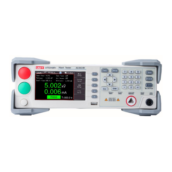
Page 8: Front Panel
User’s Manual UT5300X+ and UT5320R-SxA Series Reailable Operation This series tester use full isolation measures between the entire circuit modules, it has strong anti-interference ability. High voltage module is DA standard, controllable sine wave generator, class AB power amplifier, 40~600 Hz step-up high tension transformer, and close-loop control of output voltage with hardware and software protection, which greatly improving the reliability of the instrument. - Page 9 User’s Manual UT5300X+ and UT5320R-SxA Series Print SC key LOCK key Full function digital/character keyboard is to input data or enter Digital key characters when requested for note information such as file name. Test key is to display the measured result and for selection. Setup key is to set test condition and for selection.
- Page 10 User’s Manual UT5300X+ and UT5320R-SxA Series <System Setup> page,if [Safety Lock] function is enabled, then the external should provide online lock signal. Otherwise, this instrument is not allowed to start the test. Remote signal input/output terminal. HANDLER interface It can input the control signal of RESET and START. Use RELAY junction to output the signal of PASS, FAIL and TEST.
-
Page 11: Packing List
AC/DC/IR programmable hipot tester (20 mA), four channels UT5320R-S8A AC/DC/IR programmable hipot tester (20 mA), eight channels 2. Inspect appendix for the list of accessories. If any of the accessories are missing or damaged, please contact UNI-T or local distributors of this product. Item Quantity... -
Page 12: Power Requirements
User’s Manual UT5300X+ and UT5320R-SxA Series 3. Introduction of test wire Model Name Standard/Option Picture A pair of high voltage test clips Standard High voltage test probe Standard Double head high voltage test wire Standard (no clips) (multiple channels) Double head high voltage test wire Standard (with clips) (multiple... - Page 13 If there is no display when boot the instrument for the first time, please checke whether the power cable is connected; If there is no power on, no key respond or no relay action sound, please contact UNI-T for technical support 3.6.2 Prepare Test Wire 1) Connect the red high voltage test clip (or high voltage test probe) to L, N of DUT;...
-
Page 14: Measurement Display
User’s Manual UT5300X+ and UT5320R-SxA Series 4. Measurement Display This chapater includes the contents as follows. On-screen Display Sataus Bar Test Result Screenshot Keyboard Lock 4.1 On-screen Display When high voltage stops to output, press [Test] key to enter <Measurement> page. High voltage only can be activated in measurement page. -
Page 15: Status Bar
User’s Manual UT5300X+ and UT5320R-SxA Series 4.1.1 Test Interface Name Function Description Test parameter Display test parameter and status. Time display Display real-time voltage, current and test time. Mode selection For select the operating mode of programmable hipot tester. (soft keyboard) Activate the key function in other interface at the bottom of the screen. -
Page 16: Test Result
User’s Manual UT5300X+ and UT5320R-SxA Series 4.3 Test Result Only in the measurement display interface can start high voltage to measure DUT, its test parameters must be set in the measurement interface. Figure 4-4 Test is Qualified After the test is boot-up, two big characters displays on the middle of the screen is the real-time test data. The upper part is output voltage of high voltage, unit of withstand voltage is kV. -
Page 17: Lock Keyboard
User’s Manual UT5300X+ and UT5320R-SxA Series 4.4 Screenshot The instrument has screenshot function. Plug USB to the interface on the front panel of the instrument, press [Print Sc] key to screenshot the current screen’s image and save it into USB for later use. It is recommend to plug branded U flash disk to the interface of the instrument. -
Page 18: Measurement Setup
User’s Manual UT5300X+ and UT5320R-SxA Series 5. Measurement [Setup] This chapater includes the contents as follows. Editing the Test Steps Test Mode Parameter Setting of AC Withstand Voltage Parameter Setting of DC Withstand Voltage Parameter Setting of Insulation Resistance ... - Page 19 User’s Manual UT5300X+ and UT5320R-SxA Series 5.2 [Test Mode] Setup Press [Meas Setup] key to enter setup page, use cursor key to select [Test Type] field, and use function key to select [ACW] to set the current item to AC withstand voltage test and all parameters sets to default value. [DCW] to set the current item to DC withstand voltage test and all parameters sets to default value.
- Page 20 User’s Manual UT5300X+ and UT5320R-SxA Series Frequency 50 Hz, 60 Hz 50 Hz Output frequency of AC withstand voltage. Set current scale to auto or fixed scale. If the current range sets to [Auto], the instrument will automatically select the proper current scale. Range Auto, fixed Fixed...
- Page 21 User’s Manual UT5300X+ and UT5320R-SxA Series If the current range sets to [Auto], the instrument will automatically select the proper current scale. If the current range sets to [Fixed], it is necessary to set a value at the upper limit of the current to determine the current scale, which aims to shorten the test time.
- Page 22 User’s Manual UT5300X+ and UT5320R-SxA Series Item Default Input Range Description Value Voltage (0.050~2.500) kV 0.050 kV Output voltage dureing the insulation resistance test. HI-Limit The lower limit of resistance~10.00 The upper limit of the insulation resistance alarm. G,OFF LO-Limit 0.1 M 0.1M~10.00 G The lower limit of the insulation resistance alarm.
- Page 23 User’s Manual UT5300X+ and UT5320R-SxA Series Test result explaination of insulation resistance test a) The instrument’s display format: if the display value is greater than 10 G, it will display as >10.0 GΩ. b) The insulation value is read by the interface, the default unit is M. When then instrument displays >10.0GΩ, it will read out the value which greater than 10 G.
- Page 24 User’s Manual UT5300X+ and UT5320R-SxA Series Item Input Range Default Value Description UT5320R-S4A can control channel 1,2,3,4; Scan HIGH, LOW, OPEN OPEN UT5320R-S8A can control channel 1,2,3,4,5,6,7, Setup 8; 5.7.1 Multi-channel module Multi-channel output is a built-in high voltage switching module attached to the lower part of the instrument. Through the multi-channel output module, multiple points of the component to be tested can be connected with multiple channels of the instrument at one time.
-
Page 25: System Setup
User’s Manual UT5300X+ and UT5320R-SxA Series 6. System Setup This chapater includes the contents as follows. Page Explaination of <SYSTEM 1> Page Explaination of < SYSTEM 2> Page Explaination of <System Information> 6.1 <System> Setup <System Setup> page is to set some settings that are not related to the specific test item parameters, but are related to the test scheme of the instrument. - Page 26 User’s Manual UT5300X+ and UT5320R-SxA Series (0.1~99.9)s: In multi-step test, the waiting time ① between the steps. (0.1~99.9)s,key control Step Hold 0.1 s Key control: Press [START] key to start the next ② step. Stop: If the test is failed, then stop all the test. ①...
- Page 27 User’s Manual UT5300X+ and UT5320R-SxA Series Normal: The normal test mode of the instrument. ① Cycle: Automatic cycle after the file test is ② Normal,cycle,single Step mode Normal finished. Single: Only test the current step. ③ When the reset is enabled and the test is failed, ①...
- Page 28 User’s Manual UT5300X+ and UT5320R-SxA Series 6.2 <Communication Setup> <Communication Setup> page is to set the language, date, time and the communication setting. Press [Communication Setup] to enter <SYSTEM 2> page. Figure 6-2 <SYSTEM 2> Page, Select RS232 Mode Figure 6-3 <SYSTEM 2> Page, Select LAN Mode Table 6-2 Explaination of <...
- Page 29 User’s Manual UT5300X+ and UT5320R-SxA Series If use Modbus (RTU) protocol, please set the station address of this instrument: The instrument allows use the station number ① Address 0~32 00 to brodcase communication. 1~32: The address for connecting the ② instrument’s bus.
- Page 30 User’s Manual UT5300X+ and UT5320R-SxA Series 7. File Mangement This chapter includes the contents as follows. [Storage] [Boot-up Recall] File Operating 7.1 File Managment When high voltage output is stop, press [Save] key to enter <File> page. Figure 7-1 <File Management>...
- Page 31 User’s Manual UT5300X+ and UT5320R-SxA Series 1. Enter <File> page; 2. Use cursor key to select [File 1] ~ [File 100] any filed need to be set; 3. According to the need to select save, read and delete by the function key on the screen. 7.1.4 Rename File Name Figure 7-2 Rename File Name Press left or right direction key to move the cursor;...
-
Page 32: Handler Interface
User’s Manual UT5300X+ and UT5320R-SxA Series 8. Processor Handler Interface This chapter includes the contents as follows. HANDLER Interface SIGNAL Interface 8.1 HANDLER Interface This series of tester is equipped with a 9PIN D connection terminal, which provides remote input control and output signals. - Page 33 User’s Manual UT5300X+ and UT5320R-SxA Series Figure 8-2 Time Sequency of HANDLER Table 8-2 Time Sequency of HANDLER Signal Description 1. Judge whether the TEST (under testing) signal on the interface is Use HANDLER interface to valid. Only when the TEST (under testing) signal is invalid can the start the test START signal be received.
-
Page 34: Signal Interface
User’s Manual UT5300X+ and UT5320R-SxA Series 8.2 SIGNAL Interface Figure 8-3 SIGNAL Interface SIGNAL interface provides a power supply with an approximate output voltage of +24V (1 pin is +24V and 2 pin is ground), output current is less than 0.5A and coordinate with HANDLER interface to control signal for indicator light, optoelectronic switch and low power solenoid value. -
Page 35: Remote Communication
User’s Manual UT5300X+ and UT5320R-SxA Series 9. Remote Communication This chapter includes the contents as follows. Interface Setting of RS-232C Interface Setting of RS-485 Interface Setting of LAN 9.1 RS-232C Interface Setting 9.1.1 RS-232 Interface RS-232 is widely used serial communication standard, it’s also called asynchronous serial communication standard. - Page 36 User’s Manual UT5300X+ and UT5320R-SxA Series 9.1.2 RS-232 Connecting Suggestion: In order to prevent electric shock, please turn off the power when plug the connector. Figure 9-1 RS-232 Connector, D-sub 9 Pin Male Head When connect the instrument to PC, use D-sbu 9 pin femal head to connect the crosswire of D-sbu 9 pin femal head The default communication setting of the instrument ...
- Page 37 User’s Manual UT5300X+ and UT5320R-SxA Series 9.3 LAN Interface Setting Figure 9-2 LAN Connector on the Rear Panel Connect LAN cable to the LAN connector of the instrument. Green LED —Illuined: connecting Blinking: communicating Orange LED —Extinguished: 10BASE-T Illuined:100BASE-TX 9.3.1 Select LAN Communication Mode Move cursor to [Communication Mode] field, use function key to select LAN.
-
Page 38: Specification
User’s Manual UT5300X+ and UT5320R-SxA Series 10. Specification This chapter includes the contens as follows. Technical Index Model and Function Environmental Requirement 10.1 Technical Index Model UT5310A+ UT5310D+ UT5310R+ UT5320R+/S4A/S8A Withstand Voltage Test Output Voltage 0.050kV—5.000kV 0.050kV—5.000kV Voltage Rnge Voltage... - Page 39 User’s Manual UT5300X+ and UT5320R-SxA Series Output ± (1.0% Setting +5V) (no load) ± (1.0% Setting +5V) Accuracy of (no load) Voltage Test ± (1.0% Reading +5V) ± (1.0% Reading +5V) Accuracy of Voltage Producing DDS signal source plus AB power signal source Mode...
- Page 40 User’s Manual UT5300X+ and UT5320R-SxA Series On-load Regulated Rate ≤1% (rated power) ≤1%(rated power) Ripple Wave (1kV) ≤3% (1kV,no load) ≤3% (1kV,no load) Discharge Automaically Automaically discharge after the discharge after the test is finished test is finished Test Range of Resistance 0.2MΩ–...
- Page 41 User’s Manual UT5300X+ and UT5320R-SxA Series I down ON: when I down < Ix < I up ,PASS; When Ix ≤ I down or Ix ≥ I up,FAIL;(condition I down < I up) I down OFF: when Ix < I up,PASS;when Ix ≥ I up,FAIL; The judgement mode of insulation resistance is the same as above.
-
Page 42: Environmental Requirement
User’s Manual UT5300X+ and UT5320R-SxA Series USB HOST Interface √(128G) Save Boot-up Paramete The setting parameter save as the default parameter, it can be automatic reload when next boot-up. Control Interface HANDLER,SINGAL Communication Protocol SCPI,Modbus RTU Communication Interface RS232C,LAN,RS485 (Option) 10.2 Model and Function Model Output... - Page 43 User’s Manual UT5300X+ and UT5320R-SxA Series 43 / 43 Instruments.uni-trend.com...
Need help?
Do you have a question about the UT5300X+ Series and is the answer not in the manual?
Questions and answers