CC-ISOBUS ISOBUS-Terminal CCI 100 Operating Manual
Hide thumbs
Also See for ISOBUS-Terminal CCI 100:
- Operating instructions manual (198 pages) ,
- Operating instructions manual (412 pages)
Table of Contents
Advertisement
Quick Links
Advertisement
Table of Contents

Related Manuals for CC-ISOBUS ISOBUS-Terminal CCI 100


Summary of Contents for CC-ISOBUS ISOBUS-Terminal CCI 100
- Page 1 Operating manual Version: 1.2 CC-ISOBUS ISOBUS-Terminal CCI 100/200...
- Page 2 Copyright © 2010 Copyright by Competence Center ISOBUS e.V. Zum Gruthügel 8 D-49134 Wallenhorst...
- Page 3 Introduction.............................7 Safety...............................8 Identification of Indications in the Operating Instructions..............8 Intended Use ............................ 9 Safety Indications for the Operator / User..................10 Safety Indications for the Installation of Electrical Devices............11 Safety indication for the "Stop" switch.................... 12 Structure and Function ........................13 Overview............................
- Page 4 The company <company name> accepts no liability for damage resulting from the failure to observe these Operating Instructions. Pos : 2 /CC-Isobus/** ** Sei tenumbruch *** * @ 8\mod_1274446340522_0.doc @ 121470 @ @ 1...
-
Page 5: Intended Use
Safety Pos : 3 /CC-Isobus/Si cherheit @ 9\mod_1287407080770_21.doc @ 148701 @ @ 1 2 Safety These Operating Instructions contain basic indications which must be observed during configuration, operation and maintenance procedures. As such, it is absolutely essential to read these instructions prior to configuration and operation. -
Page 6: Safety Indications For The Operator / User
Safety 2.3 Safety Indications for the Operator / User • Do not remove any safety mechanisms or signs. • Disconnect the power supply to the terminal during maintenance work or when using a charging device on the battery of the towing/production machine. -
Page 7: Safety Indication For The "Stop" Switch
Under no circumstances does the "Stop" switch intervene in tractor functions, i.e. neither PTO nor hydraulic functions are compromised. Further information on this point can be obtained from the machine Operating Instructions. Pos : 4 /CC-Isobus/** ** Sei tenumbruch *** * @ 8\mod_1274446340522_0.doc @ 121470 @ @ 1... -
Page 8: Structure And Function
Structure and Function Pos : 5 /CC-Isobus/Aufbau @ 9\mod_1287407034989_21.doc @ 148550 @ @ 1 3 Structure and Function 3.1 Overview 1 Front view with operating elements 4 Interface bar 2 Support 5 Nameplate 3 USB connection (under the flap) 6 Softkey swap 3.2 Nameplate... -
Page 9: Operating Elements
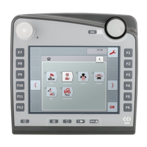
Structure and Function 3.3 Operating Elements The following operating elements are available on the terminal: 1 "Stop" switch 7 Freely assignable button 2 Daylight sensor 8 WorkingSet button 3 ESC button 9 Main menu 4 Scroll wheel 10 ON/OFF 5 Function buttons 11 Touchscreen with operating screen 6 Acknowledgement button 3.3.1... - Page 10 Structure and Function 3.3.2 ESC Button The ESC button is pressed to abort inputs and functions. The modifications made are not accepted and the previous valid value is maintained. Note The ESC button can only be used if, on the display on the operating screen, there is an ESC button operable via the touchscreen.
- Page 11 7 RS232-2 3 CAN2-IN (only CCI 200) 8 WLAN (only CCI 200) 4 Video-IN 9 LIN 5 Signal (ISO 11786) 10 ETHERNET (only CCI 200) Pos : 6 /CC-Isobus/** ** Sei tenumbruch *** * @ 8\mod_1274446340522_0.doc @ 121470 @ @ 1...
-
Page 12: Installation
Installation Pos : 7 /CC-Isobus/Installation @ 9\mod_1287407065114_21.doc @ 148634 @ @ 1 4 Installation 4.1 Installing the Terminal The device support for fixing the terminal to the tractor cab is included in the scope of delivery. Proceed as follows to install the terminal in the cab: Select a suitable position in the tractor cab (within the driver's field of vision) for fitting the terminal. - Page 13 5 Video-IN (Terminal) 13 ISOBUS cable 6 Video-IN (camera cable) 14 Signal cable 7 Signal (Terminal) 15 Camera cable 8 Signal to the terminal (Signal cable) Pos : 8 /CC-Isobus/** ** Sei tenumbruch *** * @ 8\mod_1274446340522_0.doc @ 121470 @ @ 1...
-
Page 14: Operation
Operation Pos : 9 /CC-Isobus/Bedienung @ 9\mod_1287407049442_21.doc @ 148578 @ @ 1 5 Operation 5.1 Switching on the Terminal Note Before switching on the terminal for the first time, check that the connections on the device are properly and correctly positioned. - Page 15 Operation • Slider The following buttons can be used to change between the various formats of the input dialogue for numerical values: Change to scroll wheel format. Change to slider format. Change to number block format.
- Page 16 Operation Proceed as follows to enter a numerical value: From the operating screen select the parameter whose value has to be changed. Press on the parameter on the touchscreen or turn the scroll wheel until the parameter is highlighted in white and then press on the scroll wheel. Once the parameter is highlighted you can, alternatively, also press the OK button.
- Page 17 Operation Proceed as follows to enter a Boolean value: From the operating screen select the parameter whose value has to be changed. Press on the parameter on the touchscreen or turn the scroll wheel until the parameter is highlighted in white and then press on the scroll wheel. Once the parameter is highlighted you can, alternatively, also press the OK button.
- Page 18 Operation 5.3 Setting the Terminal 5.3.1 Main Menu By pressing the button the main menu is opened. From the Main Menu there is direct access to five submenus: • Start menu • System settings • Country settings • Info and diagnosis •...
-
Page 19: System Settings
Operation 5.3.2 Start Menu In the Start Menu all active applications are shown. On the one hand, these are the applications installed on the terminal, e.g. tractor ECU and camera and, on the other, the operating images of the connected machines. •... - Page 20 Operation From each submenu you can return to the menu System Settings directly by pressing the button. 5.4.1 Display In the menu item Display adjust the following settings: Display Brightness/Day Set the desired display brightness in the day mode. The value is given as a percentage and can be adjusted in steps of 10%.
- Page 21 Operation 5.4.3 Date/Time In the menu item Date/Time adjust the following settings: Year Set the current year with four digits, e.g. "2010". Month Set the current month. Set the current day. Hour Set the current hour. The time is displayed in 24-hour format. Minutes Set the current minute.
-
Page 22: Country Settings
Operation 5.5 Country Settings In the menu item Country Settings all country and language-specific settings of the terminal can be established. Language All installed languages are shown on the selection list. Select the desired language. System of Units The terminal supports the following system of units: •... -
Page 23: Info And Diagnosis
Operation 5.6 Info and Diagnosis In the menu item Info and Diagnosis the function and status of the hardware components in the terminal can be checked. You receive the version information for installed applications. Basic information on the devices connected to the ISOBUS can be requested. -
Page 24: Service Menu
Operation One of the pieces of information described above is acknowledged with OK and you return to the menu item Info and Diagnosis. 5.7 Service Menu Attention! Settings in the service menu can only be adjusted by the manufacturer or their sales and services partners. -
Page 25: Troubleshooting
Troubleshooting Pos : 11 /CC-Is obus /Pr obl embehebung @ 9\mod_1287407073645_21.doc @ 148662 @ @ 1 6 Troubleshooting 6.1 Terminal Errors The following overview shows you possible terminal errors and how to solve them: Error Possible Cause Solution The terminal does not switch Terminal is not correctly Check ISOBUS connection connected... - Page 26 Troubleshooting 6.2.2 Testing Hardware In the menu item Info and Diagnosis - Testing Hardware the functionality of the display and operating elements can be tested. From the menu item Testing Hardware you can return to the menu Info and Diagnosis. From each of the tests you can return directly to the menu item Testing Hardware by pressing the button.
- Page 27 Troubleshooting 6.2.2.2 Testing Display Proceed as follows to test the display: Under the menu item Testing Display select the item Display Test. A coloured circle is shown. Return to the menu using the arrow button (F7). 6.2.2.3 Testing Touchscreen Proceed as follows to test the touchscreen: Under the menu item Testing Hardware select the item Touch Test.
- Page 28 Troubleshooting In order to check the functionality of the interfaces proceed as follows: Under the menu item Testing Hardware select the item Interface Test. The menu Interface Test opens on the display. Select the desired test. The selected test is shown on the screen. Press the button "Test"...
-
Page 29: Error Messages
Troubleshooting If the "Test" (F12) button is pressed the test result is displayed: Succeeded Using the interface "CAN1-IN" on the terminal a CAN message has been received. Failed No CAN message could be received using the interface "CAN1- IN" on the terminal. 6.3 Error Messages Note The error messages shown on the terminal are dependent on the connected... -
Page 30: Technical Information
Technical Information Pos : 13 /CC-Is obus /Tec hnisc he Daten @ 8\mod_1274446461913_21.doc @ 121477 @ 12222 @ 1 7 Technical Information 7.1 Mechanical Values Dimensions (WxHxD) [mm] 250 x 240 x 75 Casing Type PC-ABS multi-shell plastic casing Fastening 80mm x 80mm flange plate with 4 x M5-threaded bush Operating Temperature [°C]... - Page 31 Technical Information 7.3 Interfaces CCI 100 CAN1-IN CAN 2.0B, ISO 11898-1 M12x1; 8-pin connector CAN1-OUT CAN 2.0B, ISO 11898-1 M12x1; 8-pin connector LIN-OUT LIN-BUS Master M8x1; 4-pin socket RS232-1 Async. Up to 115 Kbps M8x1; 4-pin connector RS232-2 Async. Up to 115 Kbps M8x1;...
-
Page 32: Menu Structure
Menu Structure Pos : 15 /CC-Is obus /Menüstruktur @ 8\mod_1274875511036_21.doc @ 121660 @ 1 @ 1 8 Menu Structure Pos : 16 /CC-Is obus /*** * Seitenumbruc h * *** @ 8\mod_1274446340522_0.doc @ 121470 @ @ 1... -
Page 33: Warranty And Guarantee
Warranty and Guarantee Pos : 17 /CC-Is obus /Garanti e @ 8\mod_1274791954660_21.doc @ 121540 @ 1 @ 1 9 Warranty and Guarantee <Company name> devices are manufactured with the utmost care and using modern production methods and are subject to numerous checks. As such <company name>... -
Page 34: Contact Addresses
Contact Addresses Pos : 19 /CC-Is obus /Kontaktadr essen @ 8\mod_1274446496959_21.doc @ 121504 @ 1 @ 1 10 Contact Addresses Amazonen-Werke H. Dreyer GmbH & Co. KG Maschinenfabrik Bernard KRONE GmbH Am Amazonenwerk 9-13 Heinrich-Krone-Straße 10 D-49205 Hasbergen D-48480 Spelle Tel: + 49 (0)5405 501 0 Tel: +49 (0)5977 935 0 www.amazone.de... - Page 35 Glossary Pos : 21 /CC-Is obus /Gl oss ar @ 8\mod_1274961991767_21.doc @ 121690 @ 1 @ 1 11 Glossary Acknowledge Operating Screen The values and operating elements shown on the screen form the operating screen. The touchscreen can be used to directly select the elements shown. Competence Center ISOBUS e.V.
- Page 36 Menu Structure ..........32 ACK button ............10 Acknowledgement button ........10 Nameplate............8 Numerical values ..........14 Boolean values ...........16 Operating elements..........9 Operation ............14 Camera ...............13 Checking Stop switch .........25 Connecting the Terminal........12 Safety ..............5 Connection............12 Safety indications Connection diagram..........13 identification .............
Need help?
Do you have a question about the ISOBUS-Terminal CCI 100 and is the answer not in the manual?
Questions and answers