Table of Contents
Advertisement
Advertisement
Table of Contents

Subscribe to Our Youtube Channel
Related Manuals for CC-ISOBUS CCI 1200


Summary of Contents for CC-ISOBUS CCI 1200
- Page 1 ISOBUS Terminal CCI 1200 Operating instructions...
-
Page 3: Table Of Contents
Contents About these operating instructions About the CCI 1200 CCI.Apps Structure Safety Identification of indications in the operating instructions Intended use Safety instructions Installation of electrical devices Setting up for operation Check the scope of delivery Install the terminal Connect the terminal... - Page 4 11.2 Messages 12 Glossary 13 Disposal 14 Index Technical Information Interfaces Time zones...
-
Page 5: About These Operating Instructions I
Setting up for operation Settings User interface Apps Troubleshooting To ensure fault-free operation of your CCI 1200, please read through Liability disclaimer the operating instructions carefully. Keep the operating instructions for future reference. These operating instructions must be read and understood prior to as- sembly and commissioning of the terminal to prevent problems during operation. - Page 6 Each function is explained with step-by-step instructions. On the left Pictograms next to the operation instruction you can see the button to be pressed or one of the following pictograms: Enter a value via the keyboard Enter the value via the terminal’s screen keyboard. Select a value from a selection list 1.
-
Page 7: About The Cci 1200
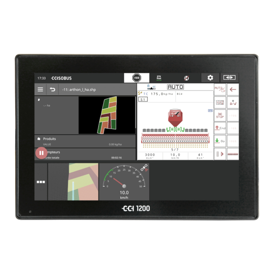
About the CCI 1200 We commend you on your purchase of this CCI 1200. The CCI 1200 is a manufacturer-independent operating terminal for controlling ISOBUS implements. The touchscreen of the CCI 1200 Is 12.1" in size and has a resolution of 1280x800 pixels, ... -
Page 8: Cci.apps
CCI.Apps The following CCI.Apps are installed on the CCI 1200: CCI.UT ISOBUS implement operation CCI.Cam Display of up to 8 cameras CCI.Config Tractor combination settings CCI.Command Map view CCI.Control Data management CCI.Help Help system The following functions must be purchased separately and can only be... -
Page 9: Structure
Structure 1. 12.1" Touchscreen 2. Light sensor 3. ON/OFF button 4. 2x USB 2.0 5. ISOBUS, supply voltage, ECU-Power 6. Signal socket, GPS 7. Camera, video multiplexer 8. 2x USB 2.0 9. Ethernet 10. Buzzer The terminal is operated via the touchscreen. All common touch ges- Touchscreen tures are supported. - Page 10 The terminal switches off automatically, ON/OFF if you pull out the ignition key or turn the ignition key to the OFF position. The terminal switches back on, when the ignition is turned on again. Note The terminal can only be switched on with the ignition key if it has previ- ously been switched off via the ignition.
- Page 11 Both USB interfaces on the left casing side are of type A. Standard flash drives can be connected. The USB interfaces on the rear side are type M12. These interfaces pro- tect the terminal against the penetration of dust and water, even when there is a connected USB device.
-
Page 13: Safety
Safety 2 Safety These operating instructions contain basic instructions which must be observed during setting up, configuration and operation. As such, it is absolutely essential to read these operating instructions prior to configu- ration and operation. Not only do the general safety instructions listed in the "Safety" chapter have to be observed but also the special safety instructions appearing in other chapters as well. -
Page 14: Intended Use
Safety Intended use The terminal is intended exclusively for use with approved ISOBUS im- plements and devices in agriculture. Any other installation or use of the terminal is not included within the manufacturer's area of responsibility. The manufacturer accepts no liability for any resulting personal injury or material damage. -
Page 15: Safety Instructions
Safety Safety instructions Warning - General Hazards! Please take special care to ensure the following safety instructions are complied with. Non-compliance could result in malfunctions and conse- quently danger for any bystanders: Switch the terminal off if the touchscreen does not respond, the dis- play hangs or the user interface is not properly displayed. -
Page 16: Installation Of Electrical Devices
Safety Installation of electrical devices Modern farming implements use electronic components and parts the operation of which can be compromised by electro-magnetic interfer- ence from other devices. Such effects can endanger people if the follow- ing safety indications are not observed. In the event of retrofitting electric and electronic devices, and/or com- ponents, in an implement with connection to the on-board network, the user must independently verify whether the installation interferes with... -
Page 17: Setting Up For Operation
Setting up for operation 3 Setting up for operation Setting the terminal up for operation is a quick and uncomplicated pro- cess based on the following step-by-step guide. Check the scope of delivery Check the scope of delivery of your terminal before you start setting up for operation: 1. -
Page 18: Connect The Terminal
Setting up for operation Connect the terminal Connect the terminal to the ISOBUS and supply it with power via con- nector A: Connect cable A to connector A of the terminal and then to the in-cab socket of the tractor. Switch on the terminal Press the ON/OFF button for 1 second. -
Page 19: Change Layout
Setting up for operation Change layout As supplied all operating screens are output in landscape format. If you have installed the device in portrait, then first change the layout: 1. Press the "Settings" button on the start screen. The "Settings" operating screen is displayed. 2. -
Page 20: Select Time Zone
Setting up for operation Select time zone The time zone forms the basis for the time displayed by the terminal. Switching between summer and winter time takes place automatically and cannot be disabled. Note Select the time zone with the correct time difference and the appropriate region. -
Page 21: Enter Terminal Licence
Setting up for operation Enter terminal licence To be able to use all functions, you must enter the terminal licence for the terminal. The terminal licence can be downloaded from the web page https://sdnord.net/PA. 1. Press the "Settings" button on the start screen. ... - Page 22 Setting up for operation 5. Change to the PC. In the browser open the web address https://sdnord/PA. 6. Answer the security question. 7. Enter the TAN of the terminal and press the button "Start activa- tion...”. The terminal licence is displayed.
- Page 23 Setting up for operation 8. On the terminal, press the "Next" button. The "Enter terminal licence" operating screen is displayed. 9. Enter the terminal licence and confirm your entry with "Next". The operating screen "Enter section control licence" is displayed. 10.
-
Page 24: Activate Apps
Setting up for operation Activate apps As supplied from the factory all apps are activated with one exception and can be used. Only the app CCI.UT2 is not activated. Activate CCI.UT2, if you want to simultaneously display and operate two ISOBUS implements, ... - Page 25 Setting up for operation You want to operate an ISOBUS implement with CCI.UT and record the Example implement data using CCI.Control. You have connected a camera to the terminal and want to keep the camera image visible during working:...
- Page 26 Setting up for operation 1. Press the button "App Menu". The app menu opens. 2. Press the "CCI.UT" button in the app menu. CCI.UT is displayed in mini view. 3. In mini view, press on "CCI.UT”. CCI.UT is displayed in the left half of the standard view. 4.
-
Page 27: Graphical User Interface
Graphical user interface 4 Graphical user interface Familiarise yourself with the essential components and the layout of the screen content. Help CCI.Help supports you in your daily work with the terminal. CCI.Help Answers questions about operation based on experience, ... -
Page 28: Touch Gestures
Graphical user interface Touch gestures The terminal is operated using the touchscreen alone. The terminal sup- ports the following common gestures: Press Press briefly at the indicated point on the touchscreen. You select an item in a selection list or trigger a function. Long press ... -
Page 29: Layout
Graphical user interface Layout During daily work with the terminal, you must be able to see all relevant information and operate several apps simultaneously. The terminal helps you to do so courtesy of it large size touchscreen and the flexible design of the user interface. Select a layout to match the terminal installation: Landscape Standard ... - Page 30 Graphical user interface Landscape Standard is described below. The descriptions can be applied to the other layouts. The display is divided into four areas: Standard View Up to 2 apps are displayed in standard view. Mini View All active apps are displayed in mini view with the exception of the apps in the standard view.
- Page 31 Graphical user interface Standard View Apps can only be operated if they are included in the Standard View. Mini View Apps in Mini View Cannot be operated, Only display the essential information, Continue running executing functions. From the fourth activated app, the Mini View extends to the right be- yond the visible area: ...
- Page 32 Graphical user interface App menu The app menu is in collapsed state. All apps that you have activated in App management are displayed in the app menu: Active apps Are displayed in Standard View, Mini View and in the app menu, ...
- Page 33 Graphical user interface Status bar The symbols in the information area of the status bar give an overview of the connection status and connection quality. No signal No GPS receiver is connected. Invalid signal A GPS receiver is connected. However, the received position data are invalid.
- Page 34 Graphical user interface You have the following operating options: Send an ISB command to all network members. Press the "ISB" button. The terminal sends the ISB command over the ISOBUS. Settings Make the basic settings before working with the terminal: ...
- Page 35 Graphical user interface Special buttons For efficient operation of the apps, the terminal provides special buttons. Action Button The Action Button provides direct access to the functions that are cur- rently most important. Burger Button Open the Burger Menu using the Burger Button. The Burger Menu offers access to the settings, functions and help system of an app: ...
- Page 36 Graphical user interface Caution! Not all ISOBUS implements support the ISB function. Consult the implement operating instructions to see which implement functions of an implement are deactivated by the ISB.
-
Page 37: Settings
Settings 5 Settings Press the "Settings" button. The "Settings" operating screen is displayed: Change the following settings directly in the "Settings" operating screen: Change screen brightness Press the "-" button to reduce the screen brightness. Press the "+" button to increase the screen brightness. Automatic screen brightness The light sensor measures the ambient light and matches the screen brightness to the ambient light. - Page 38 Settings The settings are subdivided amongst the areas "User”, "Layout”, "Sys- tem”, "Apps" and "Diagnostics”. User Adjust the operating behaviour of the terminal: Sound and touch sound, Language and units, User administration and Exhibition mode. Apps Activate and configure apps: ...
-
Page 39: User Settings
Settings Diagnostics The terminal records a log. The log is only saved on the terminal and is not transmitted. If you are having problems operating the terminal or ISOBUS implement, you can send the log to your contact: 1. Connect a flash drive to the terminal. 2. - Page 40 Settings You can change the following settings: Volume The terminal and many ISOBUS implements issue audio warnings. The volume of the audio warnings can be adjusted: 1. Press the "Volume" button. The "Volume" operating screen is displayed. 2. Press the button with the percentage. ...
-
Page 41: App Settings
Settings App settings Press the "Apps" button in the "Settings" operating screen. The "Apps" operating screen is displayed: You have the following operating options: App settings Set up the apps. App management Activate and deactivate apps. See section App management ISOBUS settings Adjust the behaviour of the terminal on the ISOBUS. - Page 42 Settings App management Apps that are not required can be switched off. This has no effect on the available CPU power or the available RAM. Note It may occur that an action cannot be performed because an app is turned off. Therefore we recommend that, ...
- Page 43 Task Controller, TECU, File server. If you operate the CCI 1200 and a second ISOBUS terminal simultane- ously, you can distribute the functions over both terminals. You operate the ISOBUS implements via the fixed ISOBUS terminal...
- Page 44 If the ISOBUS function "Universal terminal" is activated, you can operate minal up to two ISOBUS implements with the CCI 1200. This is also possible, if you simultaneously use a second ISOBUS terminal. Only deactivate the ISOBUS function "Universal Terminal", if you want to operate the terminal with no ISOBUS implements: 1.
- Page 45 Settings You are using the Task Controller of the CCI 1200 and the Task Control- Number ler of another ISOBUS terminal. Each of the two Task Controllers must have a unique number, as other- wise address conflicts on the ISOBUS may occur.
-
Page 46: System Settings
Settings TECU The ISOBUS "TECU" function sends the speed, the PTO speed, the posi- tion of the 3-point-hitch and the geolocation to the ISOBUS implement. Only switch the "TECU" off, if the TECU of the tractor displays an error message when the TECU is switched on. 1. - Page 47 Settings You have the following operating options: Terminal data In terminal data, the version of the installed software and the serial number of the terminal are displayed together with other data. The ter- minal data are required for servicing: 1. Press the "Terminal data" button. ...
- Page 48 Settings Date and time Note The terminal clock is very accurate and is set in the factory. You cannot and must not manually change the time. With an active Internet connection, the terminal adjusts the time based on a time server. ...
- Page 49 Settings Note The time and date are displayed in the selected format on the terminal and incorporated in the time stamp that the terminal sends over the ISO- BUS. We recommend adherence to the factory settings. The following settings can be made: Select time zone Select the time zone with the correct time difference and the appropriate region:...
- Page 50 Settings CCI.OS-Update The terminal software CCI.OS is constantly subject to further develop- ment and new functions are continuously being added. New versions are made available as CCI.OS-Updates, that you can order via your service partner. Caution! Before updating the terminal software all connected ISOBUS implements must be disconnected from the terminal.
- Page 51 Settings You have the following operating options: Update CCI.OS from the flash drive See section Update from the flash drive Update CCI.OS via the Internet This is the fastest and easiest way to update. Use this function, if the terminal is connected to the Internet: 1.
- Page 52 Settings Update from Note the flash drive Use a flash drive with free space of at least 200MB. The installation program saves data on the flash drive for the du- ration of the installation. Note The flash drive must remain connected to the terminal throughout the update.
- Page 53 Settings Licence data The terminal licence data must be updated under the following circum- stances: Following a CCI.OS update, After acquisition of the licence for a paid-for app. Press the "Licence data" button. The "Licence data" operating screen is displayed:...
- Page 54 Settings You have the following operating options: Update the licence data via the Internet This is the fastest and easiest update method. Use this function, if the terminal is connected to the Internet: 1. Press the "Internet" button. The licence data are updated. 2.
- Page 55 Settings Internet CCI.OS-Update and updating of the licence data can be performed quickly and easily via the Internet. You must have an active Internet connection for remote maintenance. You have the following options for connecting the terminal to the Inter- net: 1.
- Page 56 Settings You have the following operating options: Activate SmartConnect The SmartConnect is a multi-functional external add-on to the Terminal and provides, the Internet connection amongst other things: 1. Connect the SmartConnect to the terminal. 2. Switch "Activate SmartConnect" on. The terminal connects to the SmartConnect. ...
- Page 57 Settings Remote maintenance If you are having problems operating the terminal or ISOBUS imple- ment, you can grant your service partner remote access. You are the robot arm of the service partner, as the latter can indeed see the screen content but cannot perform any actions on the terminal. Note Access to the terminal via the Internet is only possible if you switch on remote maintenance.
-
Page 59: Display Of Camera Images
Display of camera images 6 Display of camera images CCI.Cam is used to display camera images. Maintain an overview of your implement and complex work processes with up to eight cameras. Cyclical camera changing makes manual switching between camera screens unnecessary. Open CCI.Cam in Standard View or Mini View. - Page 60 Display of camera images Connect two cameras To connect two cameras to the terminal, you require a video miniplexer. The video miniplexer is supplied with power from the terminal. Switch the terminal off. Connect the cameras to the video miniplexer. 3.
- Page 61 Display of camera images Connect eight cameras You can connect up to eight cameras to the terminal using the video multiplexer. Caution! The video can only supply limited power to the video multiplexer. Over- loading the power output of the terminal may result in damage to the terminal.
- Page 62 Display of camera images Note Unassigned multiplexer connections output a black camera image.
-
Page 63: Operation
Display of camera images Operation Show camera image The camera image is displayed, if you open CCI.Cam in Standard View, Maxi View or Mini View. Mirror camera image The camera image is mirrored along the vertical access. Mirroring of the camera image is, for example, useful for reversing cam- eras: CCI.Cam can only be operated in Standard View: 1. - Page 64 Display of camera images The functions described below must only be used if you have connected multiple cameras to the terminal. Show camera image continuously You want the image of a particular camera to be displayed. The camera image is to be displayed until you make another selection: 1.
- Page 65 Display of camera images Set automatic camera switching You want To switch automatically between some or all camera images and Specify the duration of display for each camera image. Change first to editing mode. 1. Press centrally on the camera screen. ...
- Page 66 Display of camera images Note If a camera image is not used for automatic camera switching, leave the camera off when selecting the sequence and display duration. Note The settings for the sequence and the display duration of the camera images are retained until you change the settings.
-
Page 67: Tractor Combination Settings
Tractor combination settings 7 Tractor combination settings You want to use Section Control and Rate Control. Both functions are lo- cation-dependent and require accurate information about the tractor combination: the type and source of the speed information, the position of the GPS receiver and ... -
Page 68: Setting Up For Operation
Tractor combination settings Setting up for operation An ISOBUS tractor makes the following tractor data available via the Tractor data ISOBUS to all network members: ground and wheel speed, PTO speed, direction of travel and position of the rear 3-point hitch. When the tractor is not connected to the ISOBUS, the terminal reads the Signal socket tractor data via the signal socket in the tractor:... - Page 69 Tractor combination settings Add a tractor: New tractor 1. Press the "Settings" button. The "Settings" operating screen is displayed: 2. Press the "Apps" button. The "Apps" operating screen is displayed: 3. Press the "CCI.Config" button. The operating screen with the CCI.Config settings is displayed: 4.
- Page 70 Tractor combination settings Distance B The distance between the GPS receiver and the tractor reference point: The distance is measured in the direction of travel. The tractor reference point is the midpoint of the rear axis. 1. Mark the mid-point of the rear axle and the position of the GPS re- ceiver on the ground using chalk next to the tractor.
- Page 71 Tractor combination settings Add an implement: New implement 1. Press the "Settings" button. The "Settings" operating screen is displayed: 2. Press the "Apps" button. The "Apps" operating screen is displayed: 3. Press the "CCI.Config" button. The operating screen with the CCI.Config settings is displayed: 4.
- Page 72 Tractor combination settings Distance D1 The distance between the coupling point and the implement reference point. With trailed implements, the reference point is on the midpoint of the first axle. With attached implements, the implement manufacturer specifies the position of the reference point.
-
Page 73: Ut And Aux
UT and AUX 8 UT and AUX You operate your ISOBUS implements with the terminal. Use the apps CCI.UT1 and CCI.UT2. Some functions of complex ISOBUS Implements can be better controlled using a joystick, a toggle switch strip or an other ISOBUS auxiliary con- trol (AUX-control or AUX). - Page 74 UT and AUX...
-
Page 75: Data Management
Data management 9 Data management CCI.Control saves, imports and exports task data. CCI.Control is used to manage your tasks and field data on the terminal. Besides importing in ISO-XML format, new tasks can also be directly created in CCI.Control. CCI.Control is used for documentation and task management: ... - Page 76 Data management This is the recommended operating mode. FMIS CCI.Control takes over the exchange of task and process data between farm PC, terminal and implement. The ISO-XML format, defined for ISOBUS, is used for data exchange. It can be provided or processed by the FMIS of appropriate farming software providers.
-
Page 77: Map View
Map view 10 Map view CCI.Command contains a detailed map view for use with Section Control and Rate Control. Using GPS, Section Control automatically switches off the sections of an Section Control ISOBUS implement upon passing over field boundaries and already treated areas and switches them back on upon leaving them. - Page 78 Map view...
-
Page 79: Troubleshooting
Troubleshooting 11 Troubleshooting Warning - behaviour in the event of technical failures Continuation of working after technical failures can result in damage to the terminal or the implement! 1. Stop working. 2. Look for a solution in this chapter of the operating instructions. 3. - Page 80 Troubleshooting With some error codes you can try to resolve the problem directly in- situ. These error codes are contained in the following table. For all other error codes, the terminal must be sent in: Number of flashes Cause/remedy The temperature measured in the terminal exceeds 95°C. Possibly the temperature sensor is defective.
-
Page 81: Problems During Operation
Troubleshooting 11.1 Problems during operation This chapter lists problems that may occur during use of the terminal. A suggestion is made for rectification for each problem. If you cannot rectify the problem based on the suggestion, contact your dealer. Problem Cause/remedy The terminal does not switch The tractor does not switch off the supply to the in-cab con-... -
Page 82: Messages
Troubleshooting 11.2 Messages The terminal indicates incorrect operation via error messages. Each er- ror message is identified by a unique error number. - Page 83 Troubleshooting Error Message text/remedy number 32000 Disconnect all implements from the terminal before restoring the factory set- tings. Check all settings once the process is completed. Continue? Not an error rather a safety note. Follow the instruction. 33033 Exporting of the licence data has failed. 1. Ensure that a flash drive is connect- ed.
- Page 84 UT number 1. The error message appears if two UTs have the same UT number. Change the UT number of the UT on the CCI 1200 or on the other ISOBUS terminal. 51003 The task data could not be imported.
- Page 85 Troubleshooting 51013 The task data could not be exported. Did you remove the flash drive before the action was completed? Repeat the process and leave the flash drive plugged in until the process has completed. 52010 Section Control: Automatic mode has been deactivated. GPS signal quality is too poor.
- Page 86 Troubleshooting...
-
Page 87: Glossary
Glossary 12 Glossary Operating screen The operating screen is comprised of the values and operating elements shown on the display. The touchscreen can be used to directly select the ele- ments shown. Boolean value A Boolean value is a value where it is only possible to choose between true/false, on/off, yes/no etc. - Page 88 Glossary ISOBUS Shortcut Button The ISB makes it possible to deactivate implement functions that have been activated via an ISOBUS terminal. This is necessary if implement operation on the termi- nal is not currently in Standard View. Which precise functions an ISB is able to deactivate on an implement, differs widely.
- Page 89 Such areas are then designated as sections. Section-specific working Satellite support use of an application map. Terminal The CCI 1200 terminal Touchscreen Touch-sensitive display for operation of the terminal.
- Page 90 Glossary Universal Serial Bus: Serial bus system to connect the terminal to a storage medium. The Universal Terminal is the human-machine inter- face (HMI) of the ISOBUS. It is the display and control device that is equipped with a screen and optional pushbuttons and rotary knobs.
-
Page 91: Disposal
Disposal 13 Disposal Dispose of a defective or no longer used terminal with due care for the environment: Dispose of the device parts in an environmentally friendly manner. Observe the local regulations. Dispose of plastics with normal domestic waste or according to the local Plastics regulations. -
Page 92: Index
Index 14 Index About ........iii CCI 1200... -
Page 93: A. Technical Information
A. Technical Information Dimensions (B x H x D) [mm] 312 x 213 x 66 Casing Type Glass fibre reinforced polyamide Fastening VESA75 Operating Temperature [°C] -15 - +70 Supply voltage [V] 12 VDC or 24VDC Permitted Range [V] 7.5 VDC - 32VDC Power consumption (at 12V) [W] 17, typical 143, maximum... -
Page 94: B. Interfaces
B. Interfaces Caution! Switch the terminal off before connecting or disconnecting connector A, B or C. Caution! All terminal connectors are mechanically protected to prevent incorrect connection or interchanging. Ensure that plugs and sockets have the same coding. Do not apply excessive force when connecting plug and socket. - Page 95 Connector A Connector type German DT, 12 pole, A-coded Type CAN1 CAN2 ECU power Power supply ISOBUS, switched ECU supply Signal Comment V+ in Supply voltage, 12VDC or 24VDC ECU Power enable Switched ECU supply voltage Power enable Switched supply voltage CAN_H...
- Page 96 Connector B Connector type German DT, 12 pole, B-coded Type RS232 ISO 11786 Signal socket, GPS/LH5000/ADS/TUVR Signal Comment V+ out 12VDC or 24VDC ISO 11786, Ground based speed Ground speed sensor ISO 11786, Wheel based speed Wheel speed sensor ISO 11786, PTO speed Power take off speed ISO 11786, In/out of work...
- Page 97 Connector C Connector type German DT, 12 pole, C-coded Type RS232 RS485 Video Camera, video miniplexer, video multi- plexer, GPS/LH5000/ADS/TUVR Signal Comment V+ out Camera power supply Video IN Video GND Earth RS485B RS485A V+ out Supply voltage Video miniplexer or video multiplexer RS232, V+ out Supply voltage RS232...
- Page 98 Connector 3 and 4 Connector type M12, 5-pole, A-coded Type USB 2.0 Signal Comment Supply voltage Data - Data + Earth Earth Connector Eth Connector type M12, 8-pole, X-coded Type Ethernet Signal Comment TR0+ TR0- TR1+ TR1- TR3+ TR3- TR2+ TR2-...
-
Page 99: C. Time Zones
C. Time zones (UTC -09:00) Alaska (UTC -08:00) Tijuana, Baja California (Mexico) (UTC -08:00) Los Angeles, Vancouver (UTC -07:00) Chihuahua, Mazatlan (UTC -07:00) Denver, Salt Lake City, Calgary (UTC -07:00) Dawson Creek, Hermosillo, Phoenix ... - Page 100 Copyright ©2017 Competence Center ISOBUS e.V. Albert-Einstein-Str. 1 D-49076 Osnabrück Document number: 20170911...
Need help?
Do you have a question about the CCI 1200 and is the answer not in the manual?
Questions and answers