Table of Contents
Advertisement
Quick Links
Advertisement
Chapters
Table of Contents
Troubleshooting

Subscribe to Our Youtube Channel
Related Manuals for CC-ISOBUS CCI 50


Summary of Contents for CC-ISOBUS CCI 50
- Page 1 Operating Instructions (EN) ISOBUS-Terminal CCI 50 ISOBUS implement control CCI.Cam Visual implement monitoring CCI.Control Documentation and task management CCI.Tecu Tractor data CCI.Command GPS track guiding and section control CCI.GPS GPS settings and tractor geometry...
- Page 2 CCI 50 ISOBUS-Terminal Operating instructions Reference: Release 5.50...
- Page 3 Copyright © 2017 Competence Center ISOBUS e.V. Albert-Einstein-Str. 1 D-49076 Osnabrück Document number: 20170315...
-
Page 4: Table Of Contents
Contents About the CCI 50 Available software Safety Identification of indications in the operating instructions Intended use Safety indications for the operator / user Safety indications for the installation of electrical devices Safety indication for the stop switch Structure and function... - Page 5 5.1.3 App toggling Country settings System settings 5.3.1 Date and time 5.3.2 App management 5.3.3 5.3.4 Touch calibration 5.3.5 Call service area 5.3.6 Licence key Info and diagnostics 5.4.1 Terminal 5.4.2 Network members 5.4.3 Storage 5.4.4 Test 5.4.5 Show error memory 5.4.6 Create screenshot ISOBUS auxiliary controls (AUX-Control)
-
Page 6: About The Cci 50
About the CCI 50 The CCI 50 is a manufacturer-independent operating terminal for controlling ISOBUS implements. The range of functions offered by the terminal is expanded by CCI.Apps. These operating instructions are an introduction to configuring and operating the terminal. It is only with knowledge of these operating instructions that accidental misuse of the terminal can be avoided and fault-free operation ensured. - Page 7 The following CCI.Apps can only be used once released by your deal- er or service partner: CCI.Command Parallel Tracking and Section Control CCI.Control Documentation and task management...
-
Page 8: Safety
1 Safety These operating instructions contain basic instructions which must be observed during configuration, operation and service. As such, it is absolutely essential to read these operating instructions prior to con- figuration and operation. Not only do the general safety indications listed in this "Safety" chap- ter have to be observed but also the special safety indications ap- pearing in other chapters as well. -
Page 9: Safety Indications For The Operator / User
Safety 1.3 Safety indications for the operator / user Do not remove any safety mechanisms or signs. Disconnect the power supply to the terminal during maintenance work or when using a charging device on the battery of the towed/production implement. -
Page 10: Safety Indications For The Installation Of Electrical Devices
Safety indications for the installation of electrical devices Modern farming implements use electronic components and parts the operation of which can be compromised by electro-magnetic interfer- ence from other devices. Such effects can endanger people if the fol- lowing safety indications are not observed. In the event of retrofitting electric and electronic devices, and/or components, in an implement with connection to the on-board net- work, the user must independently verify whether the installation in-... -
Page 11: Safety Indication For The Stop Switch
Safety 1.5 Safety indication for the stop switch A safe condition for the connected implement can be established by pressing the stop-button. In order to do so, the implement must sup- port the stop function. Caution! The stop switch has no effect on tractor functions. The power take off or hydraulic system cannot be placed in a safe state via the stop switch. -
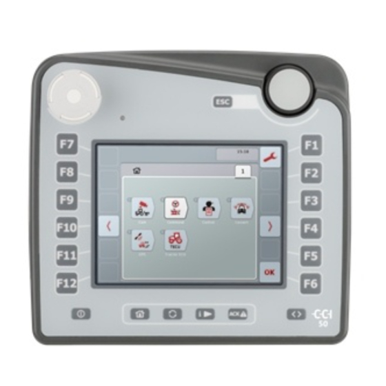
Page 12: Structure And Function
2 Structure and function Overview Front side Rear side 1. Operating elements and 3. Nameplate touchscreen 4. Interface bar 2. USB port Nameplate The nameplate features all important terminal information. 1. Terminal type 4. Hardware version 2. Manufacturer 5. Date of manufacture (week and year) 3. -
Page 13: Operating Elements
Structure and function 2.3 Operating elements The following operating elements are available on the terminal: 1. Stop switch 7. Softkey swap 2. Brightness sensor 8. Acknowledgement button 3. Touchscreen with “Main 9. i button menu“ operating screen 10. Toggle button 4. -
Page 14: Esc Button
2.3.2 ESC button The ESC button is pressed to abort inputs and functions. The modifi- cations made are not applied and the previously valid value is re- tained. Note The hardkey ESC button can only be used if there is an ESC button present on the operating display. -
Page 15: Function Keys
Structure and function 2.3.4 Function keys Six function keys (F1-F12) are arranged to the right and left of the touchscreen. Pressing a function key causes the function displayed di- rectly alongside the function key on the operating screen to be per- formed. -
Page 16: Toggle Button
2.3.8 Toggle button Only one app is ever visible on the CCI 50 display. All other apps con- tinue to run in the background. The quickest way of toggling between apps in a defined sequence is using the toggle button. -
Page 17: Touchscreen
Structure and function 2.3.11 Touchscreen The terminal is equipped with a touchscreen for menu navigation and the easy input of values and texts directly in the operating screen. By touching the screen functions can be requested directly and values changed. 2.4 Interfaces The interface bar is located on the rear of the terminal. -
Page 18: Set-Up For Operation
3 Set-up for operation Mounting the terminal The terminal is supplied with a device holder. The terminal is installed in the tractor cabin using the device holder: 1. Assemble the device holder (Figures 1 and 2). 2. Mount the device holder on the frame and terminal (Figures 3 and 3. -
Page 19: Connecting The Terminal
Set-up for operation 3.2 Connecting the terminal For connection to ISOBUS and the power supply a type A cable is necessary: Connect the "CAN1-IN" and "CAN1-OUT" on the terminal using the type A cable to the In-cab socket of the tractor. -
Page 20: Operation
4 Operation The terminal combines operation with hardkey buttons, scroll wheel and touchscreen and in this way ensures extremely efficient working. Working in the field can be disturbed by severe jolting. You can con- veniently operate the terminal and ISOBUS implement with one hand thanks to the softkey swap. -
Page 21: Entry Of Values
Operation Toggling between apps Using the toggle button you call the apps in an invariable sequence. Each time the button is pressed you switch to the next app in the se- quence. Using the i button (free button) you always call the same app. Tab view Some apps are organised in tabs. - Page 22 Making a selection Values specified by the terminal are shown in a selection list. An element is selected from a selection list using the scroll wheel or with the buttons “Down” (F5) or “Up” (F4) (4.2.4). Buttons in the input dialogue Each entry, change or selection must be confirmed.
-
Page 23: Entering Text
Operation 4.2.1 Entering text Enter text using the alphanumerical screen keyboard. Change a text as follows: 1. In the operating screen select the value that is to be changed. The screen keyboard opens. 2. Enter the new value. 3. Confirm your setting with "OK" or by pressing the scroll wheel. -
Page 24: Entering Numerical Values
4.2.2 Entering numerical values The input dialogue for numeric values has three display formats: Number pad Enter the value via the number pad or rotate the scroll wheel. Scroll wheel Rotate the scroll wheel. - Page 25 Operation Slider Drag the slider or press the "+" and "-" buttons or rotate the scroll wheel. The button for selecting the display format, is located between the buttons "OK" and "ESC": Change a numerical value as follows: 1. In the operating screen select the value that is to be changed. ...
-
Page 26: Entering A Boolean Value
4.2.3 Entering a Boolean value With a Boolean value it is only possible to select between true and false, on and off, yes and no. Display for false, off, no: Display for true, on, yes: Change a Boolean value as follows: 1. -
Page 27: Selecting A Value From A Selection List
Operation 4.2.4 Selecting a value from a selection list Some values can be selected from a selection list. Note You can display the selection list as a single line by pressing: the selection field. The selection field is located between the buttons “OK”... -
Page 28: Main Menu
Main menu Press the home button. The Main menu opens: The main menu displays all the apps and connected ISOBUS imple- ments available to you. To open an app or an ISOBUS implement press on the symbol in the icon in the main menu. -
Page 29: Settings
Settings 5 Settings The settings are subdivided across 4 tabs: User settings, Country settings, System settings and Info and Diagnostics. These are organised as follows: User settings Set the display lighting, sound, app toggling, free button as- signment and the button selection with the scroll wheel. Country settings ... -
Page 30: User Settings
User settings The operating characteristics of the terminal are set under the tab “User settings”. - Page 31 Settings The following settings can be made: Display lighting See chapter 5.1.1. Sound See chapter 5.1.2. App toggling See chapter 5.1.3. i button assignment Using the i button (free button) you always call the same app. 1. Press the button "Free button assignment" 2.
-
Page 32: Display Lighting
5.1.1 Display lighting Press the "Display lighting" button in the tab “User settings“. The “Display lighting” operating screen opens: The following settings can be made: Day lighting 1. Press the button "Day lighting". 2. Enter the display brightness for daytime operation in %. 3. - Page 33 Settings Select Lighting Mode The brightness of the display is regulated based on the lighting mode: In “Day” mode the value set in Day lighting is used. In “Night” mode the value set in Night lighting is used. ...
-
Page 34: Sound
5.1.2 Sound Press the "Sound" button in the “User settings” operating screen. The “Sound” screen opens: The following settings can be made: Beeper active Acoustic feedback for the pressing of a button on the touchscreen or a function key. 1. -
Page 35: App Toggling
Settings 5.1.3 App toggling Using the toggle button you call the apps in an invariable sequence. Each time the button is pressed you switch to the next app in the se- quence. Specify the sequence: 1. Press the button "App toggling". 2. - Page 36 The following settings can be made: Language 1. Press the “Language” button. 2. Select a language from the selection list. 3. Confirm your entry with "OK". Keyboard 1. Press the “Keyboard” button. 2. Select the keyboard from the selection list. 3.
-
Page 37: System Settings
Settings 5.3 System settings In the "System settings” tab, you can configure the terminal hard- ware and software. The following settings can be made: Date and time See chapter 5.3.1. App management See chapter 5.3.2. See chapter 5.3.3. Touch calibration See chapter 5.3.4. -
Page 38: Date And Time
5.3.1 Date and time 1. Press the "Date and time" button. The "Date and time" screen opens. The following settings can be made: Date 1. Press the button "Day". 2. Enter the current day. 3. Confirm your entry with "OK". 4. - Page 39 Settings GPS update If a GPS connection is available, the terminal date and time are automatically updated. Manual settings are overwritten: 1. Press the button "GPS update". 2. Set the Boolean value to “On”. 3. Confirm your entry with "OK". Time zone There is a table with time difference values in the appendix.
-
Page 40: App Management
5.3.2 App management Apps that are not required can be permanently disabled. The remain- ing apps then have more available CPU power and memory. To activate an app proceed as follows: 1. Press the button "App management". The “App management” screen opens: 2. - Page 41 Settings The following settings can be made: Set the terminal as the primary terminal 1. Press the button "Primary terminal". 2. Set the Boolean value to “On”. 3. Confirm your entry with "OK". Select the specific location of the terminal Possible positions are specified and cannot be freely selected.
-
Page 42: Touch Calibration
5.3.4 Touch calibration The touchscreen must be calibrated once upon commissioning: 1. Press the button "Touch calibration". The calibration view opens. Five crosses are displayed on the screen one after the other. 2. Press the centre on these crosses. 3. - Page 43 Settings Press the “Licence key” button The “Licence key” operating screen opens. Manual entry 1. Press the “Manual entry” button (F3). 2. Request the new licence key either by phone or via the website. 3. Press the “Enter licence key” button. 4.
-
Page 44: Info And Diagnostics
Info and diagnostics Under the tab “Info and diagnostics” the function and status of the software and hardware components of the terminal can be checked. You receive the version information for installed apps. Call up detailed information about the implements connected to the ISOBUS. -
Page 45: Terminal
Settings 5.4.1 Terminal Press the button "Terminal". The following operating screen opens: The following information can be displayed: Software information 1. Press the button "Software". The versions of the installed apps are displayed. 2. End the query with "OK". Show hardware information 1. -
Page 46: Network Members
5.4.2 Network members Each network member connected to the ISOBUS provides basic in- formation. This can for example be displayed for diagnostic purposes: Press the button "Network members". The Network members are identified and displayed: Note The object pool of all implements that have been connected at least once is displayed. - Page 47 Settings Delete all object pools 1. Press the button “Delete object pools” (F12). All saved object pools are deleted. 2. Restart the terminal. Delete actual object pool See section Delete actual object pool. Note After a restart, all object pools are deleted. In the event that an implement is connected, the new object pool is loaded automati- cally.
-
Page 48: Storage
5.4.3 Storage If it is no longer possible to store any more files on the terminal or a connected flash drive, it is likely that there is no longer any available memory on the storage. If the terminal is slow responding to user inputs, it may be because most of the RAM is being used. -
Page 49: Test
Settings 5.4.4 Test The terminal provides a wealth of information about its own state for troubleshooting purposes. In the event of a malfunction, test individual hardware components on the terminal: Press the button "Test". The following operating screen opens: The following components can be tested: Interfaces 1. - Page 50 Scroll wheel 1. Press the button "Scroll wheel". An empty circle is displayed. 2. Turn the scroll wheel clockwise. The segments of the displayed circle are highlighted. 3. Turn the scroll wheel anti-clockwise. The segment highlighting is cleared. 4.
-
Page 51: Show Error Memory
Settings CAN trace In the event of a complicated error pattern, the manufacturer's ser- vice department can help. Then a recording of data traffic on the ISOBUS, the CAN trace, can often prove helpful. The CAN trace con- tains important information about the system status. Continue working as normal during recording of the CAN trace. -
Page 52: Create Screenshot
2. To obtain detailed information about an error message in the list, press the button with the error message. Date and time, serial number, version number and text of the error message are displayed. 5.4.6 Create screenshot A picture says more than a thousand words. If you are having problems operating the terminal or ISOBUS imple- ment, you can capture an image of the screen content and send it to your contact:... -
Page 53: Isobus Auxiliary Controls (Aux-Control)
ISOBUS auxiliary controls (AUX-Control) 6 ISOBUS auxiliary controls (AUX-Control) Some functions of an ISOBUS implement can be better controlled us- ing a joystick, a toggle switch strip or some other auxiliary control (AUX). Assignment The desired implement functions are assigned just once to the availa- ble operating elements on the operating unit. - Page 54 Remove assignment 1. Open the main menu. 2. Press the button "AUX". The operating screen "AUX assignment" opens with a list of the available implement functions. 3. Select the implement function from the selection list. The selection list "Available AUX inputs" appears. 4.
- Page 55 ISOBUS auxiliary controls (AUX-Control) Checks Upon completing the assignment, check the assignment of the auxil- iary control: 1. Open the main menu. 2. Press the button "Implement0". The auxiliary control with the assigned implement functions opens. Note No changes to the assignment can be made in this operating screen.
-
Page 56: Troubleshooting
7 Troubleshooting Terminal errors The following overview shows possible terminal errors and how to solve them: Error Possible cause / remedy The terminal Terminal is not correctly connected does not Check the ISOBUS connector switch on Ignition is not switched on. Start the tractor The software Bus terminator missing... -
Page 57: Error Messages
Troubleshooting 7.2 Error messages The following overview shows error messages in CCI.Cam, their pos- sible cause and how to rectify them: Error Possible cause / remedy Video multi- Error at the cable connection plexer could Check that all the cables are properly connected. not be initial- Restart the terminal. -
Page 58: Glossary
8 Glossary Acknowledge Operating screen The operating screen is comprised of the values and operating elements shown on the screen. The touchscreen can be used to directly select the ele- ments shown. Boolean value A Boolean value is a value whereby it is only possible to choose between true/false, on/off, yes/no etc. - Page 59 Button Hardware operating element (hardkey), e.g. the func- tion keys F1 - F12. Terminal The CCI 50 ISOBUS terminal Touchscreen Touch-sensitive screen for operation of the terminal. Universal Serial Bus: Serial bus system to connect the terminal to a storage medium.
-
Page 60: Index
9 Index ACK button ........8 Menu structure ......55 Acknowledgement button ....8 Activate apps ....... 33 Nameplate ........5 Assign implement function ..46 Navigation check assignment ...... 48 back to the main menu....13 Breadcrumbs ......13 tab view ........ - Page 61 Index Connecting ....... 12 Touch Calibration ......35 Hardware version ....5, 38 Troubleshooting ......49 Mounting ......... 11 Serial number ......5, 38 Terminal data ........ 5 Volume ........27 Terminal on the implement ... 34 Terminal on the tractor ....34 Toggle button ........
-
Page 62: A. Appendix
A. Appendix Menu structure... -
Page 63: Time Zones
Index Time zones (UTC -09:00) Alaska (UTC -08:00) Tijuana, Baja California (Mexico) (UTC -08:00) Los Angeles, Vancouver (UTC -07:00) Chihuahua, Mazatlan (UTC -07:00) Denver, Salt Lake City, Calgary (UTC -07:00) Dawson Creek, Hermosillo, Phoenix ... - Page 64 CCI.Cam Visual implement monitoring Operating instructions Reference: CCI.Cam v5...
- Page 65 Introduction ............................. 3 About these operating instructions ....................3 Reference ............................3 About CCI.Cam ..........................3 Safety ............................... 4 Identification of indications in the operating instructions ..............4 Set-up for operation ..........................5 Mounting the terminal ........................5 Connecting the Terminal ........................5 Connecting to a camera ........................
-
Page 66: Introduction
Enhanced functions such as cyclical camera switching and flexible configuration of the camera connections facilitates day-to-day working. The snapshot function allows photos to be taken and stored on a flash drive. Pos : 3 /CC-Isobus/Si cherheit @ 8\mod_1273562473695_6.doc @ 120017 @ 122222... -
Page 67: Safety
Non-observance can entail damage to or destruction of the terminal and other malfunctions. Note The note symbol highlights operation tips and other particularly useful information. Pos : 4 /CC-Isobus/** ** Sei tenumbruch *** * @ 8\mod_1274446340522_0.doc @ 121469 @... -
Page 68: Set-Up For Operation
– Set-up for operation CCI.Cam CCI.Cam Pos : 5 /CC-Isobus/Aufbau @ 8\mod_1273585112215_6.doc @ 120207 @ 12223333333332 Pos : 7 /CC-Isobus/Installation @ 8\mod_1273570481145_6.doc @ 120033 @ 1223333 3 Set-up for operation 3.1 Mounting the terminal For information about installing the terminal, please refer to chapter 5.1 Mounting the terminal in the ISOBUS Terminal CCI 100/200 Operating Instructions. -
Page 69: Connecting To Multiple Cameras
– Set-up for operation CCI.Cam CCI.Cam 3.4 Connecting to multiple cameras Multiple cameras can be connected via one multiplexer (up to eight cameras) or one miniplexer (up to two cameras). 3.4.1 With one multiplexer Up to eight cameras can be connected to the terminal via one multiplexer. If more than 3 cameras are connected to the terminal via the multiplexer, the multiplexer requires an external power supply. -
Page 70: Installing The Software
– Set-up for operation CCI.Cam CCI.Cam 3.4.2 With a miniplexer Up to two cameras can be connected to the terminal via one miniplexer. Miniplexer connection Connection of the miniplexer to the terminal is similar to the connection of a camera via the "video" interface (see chapter 3.3). 3.5 Installing the software CCI.Cam is included in the scope of delivery of the CCI ISOBUS terminal, i.e. -
Page 71: Operation
– Operation CCI.Cam CCI.Cam 4 Operation 4.1 Program start CCI.Cam is activated automatically by switching on the terminal. To switch to the main view of CCI.Cam, proceed as follows: Press on the "Cam" button in the main menu of the terminal on the touchscreen or turn the scroll wheel until the button is highlighted in white and then press on the scroll wheel. -
Page 72: Main View (One Camera)
– Operation CCI.Cam CCI.Cam 4.2 Main view (one camera) This is the main view if only one camera is connected to the terminal. The image from this camera is displayed in the main view. You have the following operating options: Select full-screen mode Mirror image Take a snapshot... - Page 73 – Operation CCI.Cam CCI.Cam 4.2.1 Select full-screen mode To select the full-screen mode, proceed as follows: In the touchscreen press on the button "Full screen mode" (F8), directly on the camera image display or on the scroll wheel. → The view changes immediately to full-screen mode, the camera image takes up the entire monitor area.
-
Page 74: Main View (Multiple Cameras)
– Operation CCI.Cam CCI.Cam 4.3 Main view (multiple cameras) This is the main view when multiple cameras are connected to the terminal. The images from the selected cameras are displayed in the main view. You have the following operating options: Select full-screen mode (see chapter 4.2.1) Mirror image (see chapter 4.2.2) Create a snapshot (see chapter 4.2.3) - Page 75 – Operation CCI.Cam CCI.Cam 4.3.1 Activate/deactivate automatic mode If you do not want to change the display of the camera images manually, you can activate automatic mode. The display will then automatically switch to the different camera images at regular intervals. To switch the automatic camera switching on or off, proceed as follows: Press the "Switch on automatic camera switching"...
- Page 76 – Operation CCI.Cam CCI.Cam 4.3.3 Show additional cameras Note Function keys 3, 4 and 5 (F3, F4, F5) can each be allocated to two cameras in CCI.Cam. Therefore when allocating cameras to function keys not only are function keys 1, 2, 3, 4 and 5 available for selection but also function keys 3 (2), 4 (2) and 5 (2) (see chapter4.4.1).
-
Page 77: Settings
– Operation CCI.Cam CCI.Cam 4.4 Settings Use the "Settings" (F12) button in the main view to get to the Settings submenu. You have the following operating options: Change to function key assignment Change to settings in automatic mode Enter time interval Activate / deactivate video miniplexer Activate/deactivate MiniView Reset all settings... - Page 78 – Operation CCI.Cam CCI.Cam 4.4.1 Assignment This submenu facilitates the flexible assignment of cameras to the function keys independently of the connection assignment on the multiplexer. This makes it possible to set the two most important cameras to the function keys "Function key 1"...
- Page 79 – Operation CCI.Cam CCI.Cam 4.4.1.1 Assigning the function keys To assign a function key to a camera, proceed as follows: Press on one of the "Camera 1-8" buttons on the touchscreen or turn the scroll wheel until the button in question is highlighted in white and then press on the scroll wheel.
- Page 80 – Operation CCI.Cam CCI.Cam 4.4.2 Automatic mode In automatic mode, automatic switching between the images of several cameras occurs. To change automatic mode settings proceed as follows: Press on the "Automatic mode" button on the touchscreen or turn the scroll wheel until the button is highlighted in white and then press on the scroll wheel.
- Page 81 – Operation CCI.Cam CCI.Cam 4.4.2.1 Activate/deactivate camera images for automatic mode To activate/deactivate the individual camera images for automatic mode, proceed as follows: Press on the "Camera 1-8" button on the touchscreen or turn the scroll wheel until the button in question is highlighted in white and then press on the scroll wheel.
- Page 82 – Operation CCI.Cam CCI.Cam 4.4.3 Enter time interval To enter the time interval for the automatic camera switching, proceed as follows: Press on the "Time interval" button on the touchscreen or turn the scroll wheel until the button is highlighted in white and then press on the scroll wheel. Once the button is highlighted you can, alternatively, also press the "OK"...
- Page 83 – Operation CCI.Cam CCI.Cam Note The camera image displayed in MiniView is the one that was last displayed in CCI.Cam. Automatic camera switching is not available in MiniView. Note You can only specify whether CCI.Cam should make the camera images available for other applications via the MiniView setting.
-
Page 84: Troubleshooting
– Troubleshooting CCI.Cam CCI.Cam 5 Troubleshooting 5.1 Terminal errors The following overview shows possible terminal errors and how to solve them: Error Possible cause Rectification • • The terminal does not switch Terminal is not correctly Check ISOBUS connected connection •... - Page 85 – Troubleshooting CCI.Cam CCI.Cam Note Other error messages may be displayed on the terminal that are dependent on the implement. A detailed description of these possible error messages and troubleshooting can be found to in the implement operating instructions. Note If the implement cannot be operated, check whether the "stop switch"...
-
Page 86: Menu Structure
– Menu structure CCI.Cam CCI.Cam 6 Menu structure Pos : 17 /CC-Is obus /Garanti e @ 8\mod_1274791954660_6.doc @ 121539 @ 1 Pos : 19 /CC-Is obus /Kontaktadr essen @ 8\mod_1274446496959_6.doc @ 121502 @ 1 Pos : 20 /CC-Is obus /*** * Seitenumbruc h * *** @ 8\mod_1274446340522_0.doc @ 121469 @ Pos : 21 /CC-Is obus /Gl oss ar @ 8\mod_1274961991767_6.doc @ 121689 @ 1... -
Page 87: Glossary
– Glossary CCI.Cam CCI.Cam 7 Glossary Boolean value A Boolean value is a value whereby it is only possible to choose between true/false, on/off, yes/no etc. Competence Center ISOBUS e.V. CCI.Cam Visual implement monitoring ISOBUS ISO 11783 International standard for data transfer between farming implements and devices. -
Page 88: Buttons And Icons
8 Buttons and icons CCI.Cam Full-screen mode Snapshot Mirror image Switch automatic mode on/off Settings Show camera image Show additional cameras Time interval Function key assignments Automatic mode settings Reset Select from a list Video miniplexer MiniView... -
Page 89: Index
9 Index Multiplexer connection ......... 6 Activate / deactivate miniplexer ......19 Activate/deactivate camera images for automatic Operation ............. 8 mode ............... 18 Assigning the function keys ........ 16 Program start ............8 Assignment ............15 Automatic mode ..........17 Reference ............ - Page 90 CCI.Control Documentation and task management Operating instructions Reference: CCI.Control v4...
- Page 91 Introduction ............................. 3 About these operating instructions ....................3 Reference ............................3 About CCI.Control ..........................3 Safety ............................... 7 Identification of indications in the operating instructions ..............7 Set-up for operation ..........................8 Connecting the Terminal ........................8 Installing the software ........................10 Operating modes ..........................
-
Page 92: Introduction
– Introduction CCI.Control CCI.Control Pos : 1 /CC-Isobus/Ei nlei tung @ 8\mod_1273561492335_6.doc @ 119978 @ 1 1 Introduction 1.1 About these operating instructions These operating instructions are intended as an introduction to the operation and configuration of the CCI.Control app. This app is preinstalled on your ISOBUS CCI 100/200 terminal and can only be run there. - Page 93 – Introduction CCI.Control CCI.Control 1.3.2 Section-specific processing If a GPS receiver is connected, section-specific processing can be automated. Tasks planned on the PC using application maps can be processed in this way and documented with position information. 1.3.3 Standalone mode In the simplest case, CCI.Control can be operated without a task file and without an ISOBUS implement.
- Page 94 – Introduction CCI.Control CCI.Control 1.3.5 Operation with an FMIS This is the recommended operating mode. CCI.Control takes over the exchange of task and process data between farm PC, terminal and implement. The ISO-XML format, defined for ISOBUS, is used for data exchange.
- Page 95 – Introduction CCI.Control CCI.Control 1.3.6 Examples Example 1: During the harvest, a yield map was created. Based on this, a fertilisation plan is drawn up on the PC. The FMIS creates a task based on recommended fertiliser and position data, taking into consideration the functions of the implement. This is saved on a flash drive and transferred to the driver, who then imports the data to CCI.Control.
-
Page 96: Safety
Non-observance can entail damage to, or the destruction of, the terminal as well as malfunctions. Note The note symbol highlights operation tips and other particularly useful information. Pos : 4 /CC-Isobus/** ** Sei tenumbruch *** * @ 8\mod_1274446340522_0.doc @ 121469 @... -
Page 97: Set-Up For Operation
– Set-up for operation CCI.Control CCI.Control Pos : 5 /CC-Isobus/Aufbau @ 8\mod_1273585112215_6.doc @ 120207 @ 12223333333332 Pos : 7 /CC-Isobus/Installation @ 8\mod_1273570481145_6.doc @ 120033 @ 1223333 3 Set-up for operation 3.1 Connecting the Terminal 3.1.1 Connecting with a GPS receiver The use of a GPS receiver is required in order to process a section-specific task. - Page 98 – Set-up for operation CCI.Control CCI.Control 3.1.2 Connecting with a GSM modem As an alternative to importing and exporting task data using a flash drive, CCI.Control can use a mobile communications interface for online data transfer. Note The apps CCI.Courier or CCI.farmpilot must be enabled for online data transfer. This requires a GSM modem.
-
Page 99: Installing The Software
– Set-up for operation CCI.Control CCI.Control 3.2 Installing the software CCI.Control is included in the scope of delivery of the ISOBUS CCI terminal and, as a consequence, installation is neither possible nor required. In order to be able to operate the software installed ex works a licence must be acquired: As an option when The software is enabled ex works and can be used... -
Page 100: Operating Modes
12. Print out the task report if required. 13. Export the task data to the flash drive or via online transfer (cf. Section 4.6). 14. Import the compiled data to the FMIS and analyse it. Pos : 9 /CC-Isobus/Bedienung @ 8\mod_1273573299873_6.doc @ 120150 @ 122333323323333442222... -
Page 101: Operation
– Operation CCI.Control CCI.Control 4 Operation 4.1 General instructions 4.1.1 Input fields The length of the input fields for text is limited to 32 characters. Only the email address can include 64 characters. Numerical input fields are limited to 10 (e.g. the postcode) or 20 characters (e.g. telephone number). - Page 102 – Operation CCI.Control CCI.Control From the list, select the required specification. To do so, press the button with the required specification on the touchscreen or turn the scroll wheel until this button is highlighted in white. → The selection appears in the selection window. Confirm the selection with “OK”;...
- Page 103 – Operation CCI.Control CCI.Control 4.1.3 Reset filter To reset the filter setting, proceed as follows: Press the "Reset filter" button (F3) on the touchscreen. Note The filter will be reset without an additional request. 4.1.4 Sort To sort a saved list in alphabetical or reverse alphabetical order, proceed as follows: Press the "A-Z"...
-
Page 104: Program Start
– Operation CCI.Control CCI.Control 4.2 Program start CCI.Control is started automatically by switching on the terminal. There is direct access to all functions via the start screen. To switch to the CCI.Control start screen, proceed as follows: Press the “Control” button in the main menu of the terminal on the touchscreen or turn the scroll wheel until the button is highlighted in white and then press the scroll wheel. - Page 105 – Operation CCI.Control CCI.Control CCI.Control is organised into 5 areas: 4.2.1 Tasks Task processing (Section 4.4). 4.2.2 Database Inputting or modification of master data. If you plan and control your tasks using an FMIS system the master data are imported along with the task data. Thus, in general, the master data do not need to be entered manually and can be returned to the FMIS by exporting the task data.
-
Page 106: Database
– Operation CCI.Control CCI.Control 4.3 Database The master data are requested via the Database menu item. All data and information in relation to the task is summarised in the database: Customers Farms Fields Drivers Implements ... - Page 107 – Operation CCI.Control CCI.Control 4.3.1 Customers A list of the saved customers can be found under the Customers menu item. Note A customer is usually the owner or tenant of the farm on which the task is executed. A customer can be referred to from a task, a farm and a field. Customer data include ...
- Page 108 – Operation CCI.Control CCI.Control You have the following operating options: Add customers Edit/Display customers Copy customers Delete customers 4.3.1.1 Add new customers To add a new customer, proceed as follows: On the touchscreen press on the "Add new" button (F10). →...
- Page 109 – Operation CCI.Control CCI.Control 4.3.1.2 Edit/Display customers To edit/display a saved customer, proceed as follows: From the list of customers, select the customer whose information needs to be edited/displayed. To this end, press the button with the customer name on the touchscreen or turn the scroll wheel until this button is highlighted in white and then press the scroll wheel.
- Page 110 – Operation CCI.Control CCI.Control 4.3.1.3 Copy customers To copy a customer, proceed as follows: From the list of customers, select the customer that needs to be copied. To do so, press the button with the customer name on the touchscreen or turn the scroll wheel until this button is highlighted in white and then press the scroll wheel.
- Page 111 – Operation CCI.Control CCI.Control 4.3.1.4 Delete customers To delete a customer, proceed as follows: From the list of customers, select the customer that needs to be deleted. To do so, press the button with the customer name on the touchscreen or turn the scroll wheel until this button is highlighted in white and then press the scroll wheel.
- Page 112 – Operation CCI.Control CCI.Control 4.3.2 Farms A list of the saved farms can be found under the Farms menu item. Note The farm is the holding of a customer. All the fields owned by the customer comprise the farm. A customer can have several farms. A farm can be referred to from a task and a field.
- Page 113 – Operation CCI.Control CCI.Control You have the following operating options: Add farm Edit/Display farm Copy farm Delete farm 4.3.2.1 Add new farm To add a new farm, proceed as follows: On the touchscreen press on the "Add new" button (F10). →...
- Page 114 – Operation CCI.Control CCI.Control 4.3.2.2 Edit/Display farm To edit/display a saved farm, proceed as follows: From the list of farms, select the farm for which the information needs to be edited/displayed. To do so, press the button with the farm name on the touchscreen or turn the scroll wheel until this button is highlighted in white and then press the scroll wheel.
- Page 115 – Operation CCI.Control CCI.Control 4.3.2.3 Copy farm To copy a farm, proceed as follows: From the list of farms, select the farm that needs to be copied. To do so, press the button with the farm name on the touchscreen or turn the scroll wheel until this button is highlighted in white and then press the scroll wheel.
- Page 116 – Operation CCI.Control CCI.Control 4.3.2.4 Delete farm To delete a farm, proceed as follows: From the list of farms, select the farm that needs to be deleted. To do so, press the button with the farm name on the touchscreen or turn the scroll wheel until this button is highlighted in white and then press the scroll wheel.
- Page 117 – Operation CCI.Control CCI.Control 4.3.3 Fields A list of the saved fields can be found under the Fields menu item. Note A field is the area to which a task can be allocated. The field data are comprised of Field name, ...
- Page 118 – Operation CCI.Control CCI.Control You have the following operating options: Import field boundary in shape format Add field Edit/Display field Copy field Delete field Call up Map View preview...
- Page 119 – Operation CCI.Control CCI.Control 4.3.3.1 Import field boundary in shape format You can import a field boundary in shape format from the flash drive or via an online connection. In an online import, CCI.Courier receives the shape data and automatically makes it available to CCI.Control via the inbox of the terminal.
- Page 120 – Operation CCI.Control CCI.Control 4.3.3.2 Add new field To add a new field, proceed as follows: On the touchscreen press on the "Add new" button (F10). → The following operating screen opens: In the operating screen, select all parameters one after the other. To do so, press the parameter on the touchscreen or turn the scroll wheel until the button is highlighted in white and then press the scroll wheel.
- Page 121 – Operation CCI.Control CCI.Control 4.3.3.3 Edit/Display field To edit/display a saved field, proceed as follows: From the list of fields, select the field for which the information needs to be changed/displayed. To do so, press the button with the field name on the touchscreen or turn the scroll wheel until this button is highlighted in white and then press the scroll wheel.
- Page 122 – Operation CCI.Control CCI.Control 4.3.3.4 Copy field To copy a field, proceed as follows: From the list of fields, select the field that needs to be copied. To do so, press the button with the field name on the touchscreen or turn the scroll wheel until this button is highlighted in white and then press the scroll wheel.
- Page 123 – Operation CCI.Control CCI.Control 4.3.3.5 Delete field To delete a field, proceed as follows: From the list of fields, select the field that needs to be deleted. To do so, press the button with the field name on the touchscreen or turn the scroll wheel until this button is highlighted in white and then press the scroll wheel.
- Page 124 – Operation CCI.Control CCI.Control 4.3.3.6 Call up Map View preview To call up the Map View preview, proceed as follows: Go to the operating screen of the field (cf. 4.3.3.3). Press the "Map View" button (F3) on the touchscreen. → The Map View preview opens: You have the following operating options: Magnifying the map view Press the "Zoom in"...
- Page 125 – Operation CCI.Control CCI.Control 4.3.4 Drivers A list of the saved drivers can be found under the drivers menu item. Note A driver executes the planned task and operates the implement. The driver data are comprised of Name, First name, ...
- Page 126 – Operation CCI.Control CCI.Control 4.3.4.1 Add new driver To add a new driver, proceed as follows: On the touchscreen press on the "Add new" button (F10). → The following operating screen opens: In the operating screen, select all parameters one after the other. To do so, press the parameter on the touchscreen or turn the scroll wheel until the button is highlighted in white and then press the scroll wheel.
- Page 127 – Operation CCI.Control CCI.Control 4.3.4.2 Edit/show driver To edit/display a saved driver, proceed as follows: From the list of drivers, select the driver whose information needs to be edited/displayed. To do so, press the button with the driver name on the touchscreen or turn the scroll wheel until this button is highlighted in white and then press the scroll wheel.
- Page 128 – Operation CCI.Control CCI.Control 4.3.4.3 Copy driver To copy a driver, proceed as follows: From the list of drivers, select the driver that needs to be copied. To do so, press the button with the driver name on the touchscreen or turn the scroll wheel until this button is highlighted and then press the scroll wheel.
- Page 129 – Operation CCI.Control CCI.Control 4.3.4.4 Delete driver To delete a driver, proceed as follows: From the list of drivers, select the driver that needs to be deleted. To do so, press the button with the driver name on the touchscreen or turn the scroll wheel until this button is highlighted in white and then press the scroll wheel.
- Page 130 – Operation CCI.Control CCI.Control 4.3.5 Implement A list of the saved implements can be found under the Implements menu item. The list contains implements which have been transferred from the FMIS in the transfer file, as well as the ISOBUS implements which have been connected to the terminal since the last import.
- Page 131 – Operation CCI.Control CCI.Control 4.3.5.1 Edit/Display implement Note An implement can only be edited if the data were not imported from the FMIS. To edit/display a saved implement, proceed as follows: From the list of implements, select the implement for which the information needs to be edited/displayed.
- Page 132 – Operation CCI.Control CCI.Control 4.3.5.2 Delete implement To delete an implement, proceed as follows: From the list of implements, select the implement that needs to be deleted. To do so, press the button with the implement name on the touchscreen or turn the scroll wheel until this button is highlighted in white and then press the scroll wheel.
- Page 133 – Operation CCI.Control CCI.Control 4.3.6 Products A list of the saved products can be found under the Products menu item. Note A product is applied to or removed from a field as part of an agricultural practice, e.g. fertiliser, pesticide or harvested product. A product is indicated solely by the ...
- Page 134 – Operation CCI.Control CCI.Control 4.3.6.1 Add new product To add a new product, proceed as follows: On the touchscreen press on the "Add new" button (F10). → The following operating screen opens: In the operating screen, select all parameters one after the other. To do so, press the parameter on the touchscreen or turn the scroll wheel until the button is highlighted in white and then press the scroll wheel.
- Page 135 – Operation CCI.Control CCI.Control 4.3.6.2 Edit/Display product To edit/display a saved product, proceed as follows: From the list of products, select the product for which the information needs to be edited/displayed. To do so, press the button with the product name on the touchscreen or turn the scroll wheel until this button is highlighted in white and then press the scroll wheel.
- Page 136 – Operation CCI.Control CCI.Control 4.3.6.3 Copy product To copy a product, proceed as follows: From the list of products, select the product that needs to be copied. To do so, press the button with the product name on the touchscreen or turn the scroll wheel until this button is highlighted in white and then press the scroll wheel.
- Page 137 – Operation CCI.Control CCI.Control 4.3.6.4 Delete product To delete a product, proceed as follows: From the list of products, select the product that needs to be deleted. To do so, press the button with the product name on the touchscreen or turn the scroll wheel until this button is highlighted in white and then press the scroll wheel.
- Page 138 – Operation CCI.Control CCI.Control 4.3.7 Agricultural practices A list of the saved agricultural practices can be found under the Agricultural practices menu item. An agricultural practice can be allocated to a task during the planning of a task using an FMIS. An application technique such as tillage (“Plough”, “Grubber”, etc.).can also belong to an agricultural practice.
- Page 139 – Operation CCI.Control CCI.Control 4.3.7.1 Add new agricultural practice To add a new agricultural practice, proceed as follows: On the touchscreen press on the "Add new" button (F10). → The following operating screen opens: In the operating screen, select all parameters one after the other. To do so, press the parameter on the touchscreen or turn the scroll wheel until the button is highlighted in white and then press the scroll wheel.
- Page 140 – Operation CCI.Control CCI.Control 4.3.7.2 Edit/Display agricultural practice To edit/display a saved agricultural practice, proceed as follows: From the list of agricultural practices, select the agricultural practice for which the information needs to be edited/displayed. To do so, press the button with the name of the agricultural practice on the touchscreen or turn the scroll wheel until this button is highlighted in white and then press the scroll wheel.
- Page 141 – Operation CCI.Control CCI.Control 4.3.7.3 Copy agricultural practice To copy an agricultural practice, proceed as follows: From the list of agricultural practices, select the agricultural practice that needs to be copied. To do so, press the button with the name of the agricultural practice on the touchscreen or turn the scroll wheel until this button is highlighted in white and then press the scroll wheel.
- Page 142 – Operation CCI.Control CCI.Control 4.3.7.4 Delete agricultural practice To delete an agricultural practice, proceed as follows: From the list of agricultural practices, select the agricultural practice that needs to be deleted. To do so, press the button with the name of the agricultural practice on the touchscreen or turn the scroll wheel until this button is highlighted in white and then press the scroll wheel.
- Page 143 – Operation CCI.Control CCI.Control 4.3.8 Techniques A list of the saved techniques can be found under the Techniques menu item. The technique belongs to the agricultural practice that may be allocated to a task when planning the task with the FMIS. For example, the “Plough” and “Grubber” techniques belong to the agricultural practice of tillage.
- Page 144 – Operation CCI.Control CCI.Control 4.3.8.1 Add new technique To add a new technique, proceed as follows: On the touchscreen press on the "Add new" button (F10). → The following operating screen opens: In the operating screen, select all parameters one after the other. To do so, press the parameter on the touchscreen or turn the scroll wheel until the button is highlighted in white and then press the scroll wheel.
- Page 145 – Operation CCI.Control CCI.Control 4.3.8.2 Edit/Display technique To edit/display a saved technique, proceed as follows: From the list of techniques, select the technique for which the information needs to be edited/displayed. To do so, press the button with the name of the technique on the touchscreen or turn the scroll wheel until this button is highlighted in white and then press the scroll wheel.
- Page 146 – Operation CCI.Control CCI.Control 4.3.8.3 Copy technique To copy a technique, proceed as follows: From the list of techniques, select the technique that needs to be copied. To do so, press the button with the name of the technique on the touchscreen or turn the scroll wheel until this button is highlighted in white and then press the scroll wheel.
- Page 147 – Operation CCI.Control CCI.Control 4.3.8.4 Delete technique To delete a technique, proceed as follows: From the list of techniques, select the technique that needs to be deleted. To do so, press the button with the name of the technique on the touchscreen or turn the scroll wheel until this button is highlighted in white and then press the scroll wheel.
- Page 148 – Operation CCI.Control CCI.Control 4.3.9 Crop types A list of the saved crop types can be found under the Crop types menu item. Note Crop type refers to the type of species or plant, such as corn or barley. A crop type is indicated solely by the ...
- Page 149 – Operation CCI.Control CCI.Control 4.3.9.1 Add new crop type To add a new crop type, proceed as follows: On the touchscreen press on the "Add new" button (F10). → The following operating screen opens: In the operating screen, select all parameters one after the other. To do so, press the parameter on the touchscreen or turn the scroll wheel until the button is highlighted in white and then press the scroll wheel.
- Page 150 – Operation CCI.Control CCI.Control 4.3.9.2 Edit/Display crop type To edit/display a saved crop type, proceed as follows: From the list of crop types, select the crop type for which the information needs to be edited/displayed. To do so, press the button with the name of the crop type on the touchscreen or turn the scroll wheel until this button is highlighted in white and then press the scroll wheel.
- Page 151 – Operation CCI.Control CCI.Control 4.3.9.3 Copy crop type To copy a crop type, proceed as follows: From the list of crop types, select the crop type that needs to be copied. To do so, press the button with the name of the crop type on the touchscreen or turn the scroll wheel until this button is highlighted in white and then press the scroll wheel.
- Page 152 – Operation CCI.Control CCI.Control 4.3.9.4 Delete crop type To delete a crop type, proceed as follows: From the list of crop types, select the crop type that needs to be deleted. To do so, press the button with the name of the crop type on the touchscreen or turn the scroll wheel until this button is highlighted in white and then press the scroll wheel.
- Page 153 – Operation CCI.Control CCI.Control 4.3.9.5 Crop varieties A list of the saved crop varieties can be found under the Crop varieties menu item. Note Crop variety refers to a special variety or breed of a crop type. A crop variety is indicated solely by the ...
-
Page 154: Task Data
– Operation CCI.Control CCI.Control 4.4 Task data The task data comprise all data and information in relation to the task: Name of the task, Customer, City, Farm, Field, Crop type, Crop variety, Worker, ... - Page 155 – Operation CCI.Control CCI.Control 4.4.2 Tasks The task list is brought up via the Tasks menu item. You have the following operating options: Sort task list Add task Show task Edit task Copy task Delete task Import application map in shape format...
- Page 156 – Operation CCI.Control CCI.Control 4.4.2.1 Sort task list The task list can not only be sorted in alphabetical or reverse alphabetical order (cf. Section 4.1.4), but also according to the distance from the field assigned to the task. To sort the list of saved tasks, proceed as follows: Press the "Z-A"...
- Page 157 – Operation CCI.Control CCI.Control 4.4.2.2 Add new task To add a new task, proceed as follows: On the touchscreen press on the "Add new" button (F10). → The following operating screen opens: In the operating screen, select all parameters one after the other. To do so, press the relevant parameter on the touchscreen or turn the scroll wheel until the button is highlighted in white and then press the scroll wheel.
- Page 158 – Operation CCI.Control CCI.Control 4.4.2.3 Show task To display a task, proceed as follows: On the touchscreen, press the button with the task or turn the scroll wheel until this button is highlighted in white and then press the scroll wheel. Once the button is highlighted you can, alternatively, also press the "OK"...
- Page 159 – Operation CCI.Control CCI.Control 4.4.2.5 Copy task To copy a saved task, proceed as follows: From the list of tasks, select the task that needs to be copied. To do so, press the button with the task on the touchscreen or turn the scroll wheel until this button is highlighted in white and then press the scroll wheel.
- Page 160 – Operation CCI.Control CCI.Control 4.4.2.6 Delete task To delete a task, proceed as follows: From the list of tasks, select the task that needs to be deleted. To do so, press the button with the task on the touchscreen or turn the scroll wheel until this button is highlighted in white and then press the scroll wheel.
- Page 161 – Operation CCI.Control CCI.Control 4.4.2.7 Import application map in shape format You can import an application map in shape format from the flash drive or via an online connection. In an online import, CCI.Courier receives the shape data and automatically makes it available to CCI.Control via the inbox of the terminal.
- Page 162 – Operation CCI.Control CCI.Control Select the application map that is to be imported. To do so, press the button with the required application map on the touchscreen or turn the scroll wheel until this button is highlighted in white and then press the “OK” button (F6). Select the column with the data from the application map.
- Page 163 – Operation CCI.Control CCI.Control Select the measuring unit. To do so, on the touchscreen press on the button with the measuring unit or turn the scroll wheel until the button is highlighted in white. → The following selection list opens: Select the units.
- Page 164 – Operation CCI.Control CCI.Control 4.4.2.7.2 Online import To import an online application map, proceed as follows: Save the shape data on the FTP server or send it as an E-mail attachment to CCI.Courier. Press the "Import application map in shape format" button (F9) on the touchscreen.
- Page 165 – Operation CCI.Control CCI.Control 4.4.3 Detailed view In the task list, press the task. Press the “show” button in the context menu. The detailed view of the task is brought up. The detailed view of a task is divided into 6 tabs: Active task, Counters, Map, Comments, Edit task, and Report.
- Page 166 – Operation CCI.Control CCI.Control 4.4.3.1 Active task This tab displays the task times and task-specific data and information. Time counter: This shows the time at which the task started, stopped or paused. Duration: This shows the previous total time and the current duration of the task.
- Page 167 – Operation CCI.Control CCI.Control Note A stopped task cannot be continued. A stopped task remains in the list of saved tasks and cannot be deleted. Note If the terminal has been switched off without pausing or stopping the active task, a message indicating that the task was paused will appear on the terminal, the next time it is started up.
- Page 168 – Operation CCI.Control CCI.Control 4.4.3.2 Counters The total duration and the counter readings transferred from the implement are indicated under this tab. You have the following operating options: Switch to the counter readings of a different implement Press the "Switch Counter Readings" button (F6) on the touchscreen. ...
- Page 169 – Operation CCI.Control CCI.Control 4.4.3.3 A map of the field assigned to the task is displayed in this tab. You have the following operating options: Magnifying the map view Press the "Zoom in" button (F4) on the touchscreen. Shrinking the map view Press the "Zoom out"...
- Page 170 – Operation CCI.Control CCI.Control 4.4.3.3.1 Show application maps To show the application maps, proceed as follows: Press the “Show application maps” button (F6) on the touchscreen. → The application maps are displayed in the map view: 4.4.3.3.2 Adjust setpoint In order to adjust the setpoint of the application map proceed as follows: Press the "Adjust setpoint"...
- Page 171 – Operation CCI.Control CCI.Control 4.4.3.4 Comments A list of your saved comments can be found under this tab: To add a new comment, proceed as follows: On the touchscreen press on the "Add new" button (F10). Enter the new comment on the touchscreen using the keyboard. Confirm your entry with "OK".
- Page 172 – Operation CCI.Control CCI.Control 4.4.3.5 Edit task The following operating screen can be accessed under this tab: You have the following operating options: Edit task To see which operating options you have, please refer to chapter 4.4.2.4. Call up database Press on the "Database"...
- Page 173 – Operation CCI.Control CCI.Control 4.4.3.6 Report This tab contains a summary of the task data. You have the following operating options: Generate report Press the "Generate Report" button (F10) on the touchscreen. The report is exported as PDF with the task. Configure report...
- Page 174 – Operation CCI.Control CCI.Control 4.4.3.6.1 Configure report To configure a task report, proceed as follows: Press the "Configure Report" button (F12) on the touchscreen. → The following operating screen opens: Select the parameters which need to be displayed in the task report. To do so, press the parameter on the touchscreen or turn the scroll wheel until the button is highlighted in white and then press the scroll wheel.
-
Page 175: Import Task Data
– Operation CCI.Control CCI.Control 4.5 Import task data To import task data, proceed as follows: Export the required task data to the FMIS in ISO-XML format on a flash drive in the \Taskdata folder. If multiple task files are saved on the flash drive they can be organised in subfolders. - Page 176 – Operation CCI.Control CCI.Control Note The process can take a few minutes. CCI.Control will restart automatically after the data has been imported. Note If the task data are primarily imported via online transfer, the “Delete task data after import” function should be activated (cf. Section 4.7.3.3).
-
Page 177: Export Task Data
– Operation CCI.Control CCI.Control 4.6 Export task data There are two ways to export the task data: On a flash drive: For this purpose, a flash drive has to be plugged into the terminal. For online transfer: For this purpose, an app such as CCI.Courier or CCI.farmpilot, which enables task data to be transferred online, is required,. - Page 178 – Operation CCI.Control CCI.Control Select either “Flash drive” or “Online transfer”. To do so, press the button on the touchscreen with the required transfer path or turn the scroll wheel until this button is highlighted in white and then press the scroll wheel. Once the button is highlighted you can, alternatively, also press the "OK"...
-
Page 179: Settings
– Operation CCI.Control CCI.Control 4.7 Settings Here, you can activate and deactivate Auto-logging and Notification functions and call up Advanced settings. You have the following operating options: Activate/deactivate Auto-logging Activate/deactivate Notifications Bring up screen for Advanced settings... - Page 180 – Operation CCI.Control CCI.Control 4.7.1 Activate/deactivate Auto-logging Auto-logging is used to automatically and permanently document task data. This guarantees documentation even if the driver has not created or started any task himself. Auto-logging documents all the work carried out in one day in a task. These task data can be calculated and evaluated at a PC if an FMIS is used that is capable of assigning data to individual tasks.
- Page 181 – Operation CCI.Control CCI.Control 4.7.3 Advanced settings To bring up the screen for advanced settings, proceed as follows: Press the “Advanced settings” button on the touchscreen or turn the scroll wheel until this button is highlighted in white and then press the scroll wheel. Once the button is highlighted you can, alternatively, also press the "OK"...
- Page 182 – Operation CCI.Control CCI.Control 4.7.3.1 Enter function instance The function instance is the address of the task controller with which the ISOBUS implement can select a task controller, in case there are several task controllers. Note The ISOBUS implement selects the task controller with the lowest function instance.
- Page 183 – Operation CCI.Control CCI.Control 4.7.3.3 Delete task data after import Note This function is only relevant if the task data are imported via online transfer. The task data that are imported via online transfer are saved to an internal hard disk.
-
Page 184: Troubleshooting
– Troubleshooting CCI.Control CCI.Control 5 Troubleshooting 5.1 Terminal errors The following overview shows possible terminal errors and how to solve them: Error Possible cause Rectification • • The terminal does not switch Terminal is not correctly Check ISOBUS connected connection •... -
Page 185: Error Messages
– Troubleshooting CCI.Control CCI.Control 5.2 Error messages The following overview shows error messages in CCI.Control, their possible cause and how to rectify them: Error Possible cause Rectification Export is aborted, since no No flash drive plugged in. Plug in flash drive. flash drive found. - Page 186 – Troubleshooting CCI.Control CCI.Control Control has not received any Incorrect GPS receiver Check the GPS receiver valid GPS Signal. configuration. configuration. End active task? Once ended, If documentation has been Pause task. a task cannot be resumed. stopped, a task cannot be resumed.
- Page 187 – Troubleshooting CCI.Control CCI.Control storage volume and try again. Create directory failed: Import of application map failed. Import of field boundary failed. Error while trying to open shape file. Error while trying to open database file. Unsupported type of shape file.
- Page 188 – Troubleshooting CCI.Control CCI.Control Note Other error messages may be displayed on the terminal that are dependent on the implement. A detailed description of these possible error messages and troubleshooting can be found to in the implement operating instructions. Note If the implement cannot be operated, check whether the “Stop switch”...
-
Page 189: Menu Structure
– Menu structure CCI.Control CCI.Control Pos : 13 /CC-Is obus /Tec hnisc he Daten @ 8\mod_1274446461913_6.doc @ 121475 @ 12222 Pos : 15 /CC-Is obus /Menüstruktur @ 8\mod_1274875511036_6.doc @ 121659 @ 1 6 Menu structure Pos : 16 /CC-Is obus /*** * Seitenumbruc h * *** @ 8\mod_1274446340522_0.doc @ 121469 @ Pos : 17 /CC-Is obus /Garanti e @ 8\mod_1274791954660_6.doc @ 121539 @ 1 Pos : 19 /CC-Is obus /Kontaktadr essen @ 8\mod_1274446496959_6.doc @ 121502 @ 1 Pos : 20 /CC-Is obus /*** * Seitenumbruc h * *** @ 8\mod_1274446340522_0.doc @ 121469 @... -
Page 190: Glossary
– Glossary CCI.Control CCI.Control Pos : 21 /CC-Is obus /Gl oss ar @ 8\mod_1274961991767_6.doc @ 121689 @ 1 7 Glossary FMIS Field mapping system, software for yield data processing and the creation of application maps. (Farm Management Information System) Technique The technique with which the agricultural practice is performed, e.g. - Page 191 – Glossary CCI.Control CCI.Control Global System for Mobile Communication Standard for fully digital mobile phone networks, that is primarily used for telephony and text messaging such as SMS. ISO-XML ISOBUS-specific format for task data files based on XML. ISOBUS ISO11783 International standard for data transfer between farming implements and devices.
- Page 192 – Glossary CCI.Control CCI.Control Section-specific Satellite support use of an application map. processing Terminal ISOBUS CCI 100 or CCI 200 terminal Touchscreen Touch-sensitive screen for operation of the terminal. Wi-Fi (WLAN) Wireless Local Area Network Wireless local network. Extended Markup Language Logical markup language and both successor and enhancement of HTML.
-
Page 193: Isobus In Functionalities
8 ISOBUS in functionalities Task-controller basic (totals) Takes over the documentation of cumulative values that are worthwhile when looking at the work carried out. In this respect, the device makes the values available. Here the data exchange between the FMIS and the task controller is realised in ISO-XML data format. -
Page 194: Buttons And Icons
9 Buttons and icons CCI.Control Database List of customers Customer List of farms Farm List of fields Field List of drivers Drivers List of implements Implement List of products Product List of agricultural practices Agricultural practice List of crop types Crop type List of tasks Active task... - Page 195 Zoom in Zoom out Delete Edit/Display Copy Change to the right Change to the left Change up Change down Confirm selection or entry Address Phone number Mobile phone number Filter Reset filter Sort from A – Z Sort from Z – A Import application map or field boundary Select from a list in shape format...
-
Page 196: Notes
10 Notes... -
Page 197: Index
11 Index Adjust setpoint ............ 81 Enter function instance ........93 Agricultural practice ..........49 Enter time delay ..........93 Add ..............50 Error messages ..........96 Copy ..............52 Delete .............. 53 Farm ..............23 Edit ..............51 Add ..............24 show .............. - Page 198 Time delay ............93 Set-up for operation ..........8 Shape format Active task ............80 Export field boundary ........35 show application maps ........81 Import application map ........72 Master data ............17 Import field boundary........30 Agricultural practices ........49 Standalone mode ..........
- Page 199 Edit ..............38...
- Page 200 CCI.TECU Tractor data Operating instructions Reference: CCI.TECU v6...
- Page 201 Introduction ............................. 3 About these operating instructions ....................3 Reference ............................3 About CCI.TECU ..........................4 Safety ............................... 6 Identification of indications in the operating instructions ..............6 Set-up for operation ..........................7 Connecting to the signal connector ....................7 Connecting with IRB upgrade cable set ....................
-
Page 202: Introduction
CCI.TECU – Introduction Pos : 1 /CC-Isobus/Ei nlei tung @ 8\mod_1273561492335_6.doc @ 119978 @ 1 1 Introduction 1.1 About these operating instructions These Operating Instructions are intended as an introduction to the operation and configuration of the CCI.TECU app. This app is preinstalled on your ISOBUS CCI 100/200 terminal and can only be run there. -
Page 203: About Cci.tecu
CCI.TECU – Introduction 1.3 About CCI.TECU A vast range of electronic components are used in modern tractors. In addition to sensors for the capture of operating data these are, above all, comprised of electronic control units (ECUs) for the control of various tractor functions. The electronic components are, as a rule, interconnected via a so-called bus system and use this to exchange tractor information such as driving speed or power take off speed. - Page 204 CCI.TECU – Introduction power supply. Typically the implement makes use of this to save configuration parameters or to adopt a defined state. CCI.TECU offers the delayed switch off as an additional function for all tractors that are equipped with the ISOBUS IRB upgrade cable set of the CCI. Note The delayed switch off is available for all terminals from hardware generation 2.
-
Page 205: Safety
Non-observance can entail damage to, or the destruction of, the terminal as well as malfunctions. Note The note symbol highlights operation tips and other particularly useful information. Pos : 4 /CC-Isobus/** ** Sei tenumbruch *** * @ 8\mod_1274446340522_0.doc @ 121469 @... -
Page 206: Set-Up For Operation
CCI.TECU – Set-up for operation Pos : 5 /CC-Isobus/Aufbau @ 8\mod_1273585112215_6.doc @ 120207 @ 12223333333332 Pos : 7 /CC-Isobus/Installation @ 8\mod_1273570481145_6.doc @ 120033 @ 1223333 3 Set-up for operation Information on the installation and power supply as well as the connection to ISOBUS can be found in the operating instructions of your terminal. - Page 207 CCI.TECU – Set-up for operation In accordance with ISO 11786, the signal connector is assigned the following sensor data: Wheel speed sensor: It emits a specific number of electrical signals in proportion to the wheel rotation. As such, the theoretical speed of the tractor can be calculated. Ground speed sensor: It emits a specific number of electrical pulses in proportion to the distance already covered.
-
Page 208: Connecting With Irb Upgrade Cable Set
IRB upgrade cable set via the type B cable. 3.3 Installing the software CCI.TECU is included in the scope of delivery of the CCI ISOBUS terminal, i.e. installation is neither possible nor required. Pos : 8 /CC-Isobus/** ** Sei tenumbruch *** * @ 8\mod_1274446340522_0.doc @ 121469 @... -
Page 209: Operation
CCI.TECU – Operation Pos : 9 /CC-Isobus/Bedienung @ 8\mod_1273573299873_6.doc @ 120150 @ 122333323323333442222 4 Operation 4.1 Program start CCI.TECU is activated automatically by switching on the terminal. There is direct access to all functions via the main view. To switch to the main view of CCI.TECU, proceed as follows: Press on the "TECU"... -
Page 210: Main View
CCI.TECU – Operation 4.2 Main view The CCI.TECU main view provides the following information: Name of the current tractor, Speed display, Power take off speed display, 3-point hitch position display, Display for the selected speed sensor and Display for the working or transport position and the direction of travel. Note The speed display of CCI.TECU does not replace the tachometer of the tractor. - Page 211 CCI.TECU – Operation Set working position Activate documentation 4.2.1 Select tractor To select a tractor proceed as follows: On the touchscreen press the button with the name of the current tractor. If the button with the tractor name is highlighted in white you can press on the scroll wheel instead.
- Page 212 CCI.TECU – Operation 4.2.3 Select the speed sensor The speed display only evaluates one of either possible sensors. You can select between the following sensors: Wheel speed sensor Ground speed sensor To select the speed sensor, proceed as follows: Press the "Select Speed Sensor"...
- Page 213 CCI.TECU – Operation 4.2.4 Set working position In order to establish the current position of the 3-point hitch as the working position proceed as follows: Position the 3-point hitch in the desired working position. Press the "Set Working Position" button (F6) on the touchscreen. →...
-
Page 214: List Of Tractors
CCI.TECU – Operation 4.3 List of tractors You will find a list of the saved tractors under the List of Tractors menu item. The tractor data consists of the tractor name, a comment and the tractor settings. Note The current tractor is identified with a small red tractor symbol in the bottom right corner of the button. - Page 215 CCI.TECU – Operation 4.3.1 Add tractor To add a tractor proceed as follows: Press the "Add Tractor" button (F10) on the touchscreen. → A detailed view of a new tractor is opened. In the detailed view, select the desired tab. To do so, press on the tab icon on the touchscreen or change using the buttons "To the left"...
- Page 216 CCI.TECU – Operation 4.3.2.1 Copy tractor To copy a tractor proceed as follows: In the list of tractors select the tractor whose information is to be copied. To do so, on the touchscreen press the button with the tractor name or turn the scroll wheel until the button is highlighted in white and then press on the scroll wheel.
- Page 217 CCI.TECU – Operation 4.3.3 Detailed view The detailed view of a tractor is divided into 6 tabs: Overview, Comment, Tractor Settings, Speed, Power take off and 3-point hitch. The tabs Speed, Power take off and 3-point hitch are not always available: ...
- Page 218 CCI.TECU – Operation 4.3.3.1 Overview This tab shows the settings for speed, the power take off and the 3-point hitch.
- Page 219 CCI.TECU – Operation 4.3.3.2 Comment This tab shows a comment field in which notes or explanations can be inserted regarding the tractor. Note A comment is comprised of a maximum of 160 characters. If you exceed the text field limit the text field turns red and the input cannot be saved. You have the following operating options: Add comment Edit comment...
- Page 220 CCI.TECU – Operation 4.3.3.3 Tractor settings This tab shows the tractor name and the settings for wheel speed sensor, ground speed sensor, PTO sensor and 3-point hitch sensor. You have the following operating options: Edit name Select signal source Select between: ...
- Page 221 CCI.TECU – Operation 4.3.3.3.1 Edit name To edit the tractor name proceed as follows: press on the button with the tractor name on the touchscreen or turn the scroll wheel until the button is highlighted in white and then press the scroll wheel. Once the button is highlighted you can, alternatively, also press the "OK"...
- Page 222 CCI.TECU – Operation Note If you select the signal connector as the signal source for the wheel speed sensor or the ground speed sensor you must calibrate the speed or manually enter the pulses per 100 metres. More detailed information on speed calibration can be consulted in chapter 0. Note If you select the signal connector as the signal source for the 3-point hitch sensor you must calibrate the 3-point hitch.
- Page 223 CCI.TECU – Operation 4.3.3.3.5 Unlock X-Sensor If you want to operate an X-Sensor at the terminal, the terminal's input circuit must be configured. To configure the terminal's input circuit, proceed as follows: Press the “X-Sensor” button on the touchscreen or turn the scroll wheel until this button is highlighted in white and then press the scroll wheel.
- Page 224 CCI.TECU – Operation 4.3.3.4 Speed This tab shows the number of pulses emitted by the speed sensor over a distance of 100 metres. The default setting for the new addition of a tractor shows a value of 13000 Pul/100m. If the value for the number of pulses per 100 metres is known (e.g. from the sensor data sheet), this can be entered directly.
- Page 225 CCI.TECU – Operation Note Calibration is only possible for the active tractor. For all other tractors, the button "Calibrate" (F3) is greyed-out. 4.3.3.4.1 Enter the wheel speed sensor value Proceed as follows to enter the value for the pulses per 100 metres for the wheel speed sensor: Press on the "Wheel speed sensor"...
- Page 226 CCI.TECU – Operation 4.3.3.4.3 Select the hectare counter source Note The hectare counter source can only be selected if both speed sensors are used simultaneously (see chapter 4.3.3.3). In all other cases the "Hectare counter preference" is greyed-out. To select the source for the speed displayed by the hectare counter, proceed as follows: Press the “Hectare counter preference”...
- Page 227 CCI.TECU – Operation 4.3.3.4.4 Calibrate Note Where possible the speed calibration should not be carried out on smooth surfaces (e.g. asphalt), rather directly on the field. In order to calibrate the speed proceed as follows: Set out a distance of 100 metres. Press the "Calibrate"...
- Page 228 CCI.TECU – Operation 4.3.3.5 Power take off This tab shows the number of pulses emitted by the sensor per power take off revolution. Note Refer to your tractor's technical information to consult the value to be entered. Note The valid value range for the number of pulses is between 1 and 40 Pulses/revolution.
- Page 229 CCI.TECU – Operation 4.3.3.5.1 Enter Pulses/revolution value Proceed as follows to enter the value for the pulses per revolution: Press on the "Pulses/revolution" button on the touchscreen or press on the scroll wheel or on the "OK" button (F6). Enter the new value on the touchscreen using the number pad or the slider. Confirm your entry with "OK".
- Page 230 CCI.TECU – Operation 4.3.3.6 3-point hitch This tab shows the voltage values for the maximum and minimum 3-point hitch position. You have the following operating options: Calibrate Note Calibration is only possible for the active tractor. For all other tractors, the button "Calibrate"...
-
Page 231: Passive Mode
CCI.TECU – Operation 4.4 Passive mode If there is a Primary TECU or a TECU of higher priority is available in the tractor, the terminal TECU changes to passive mode automatically. In passive mode the values made available by the other TECUs are identified by a blue frame and a blue "i": If all signals are read and made available via the ISOBUS, a connection with the signal connector is not necessary... -
Page 232: Hectare Counter And Documentation
CCI.TECU – Operation 4.5 Hectare counter and documentation 4.5.1 General In general ISOBUS implements offer comprehensive options for the display and documentation of process data. Often the display and documentation of the underlying process data is however also worthwhile for implements that are not operated via the ISOBUS. - Page 233 CCI.TECU – Operation You have the following operating options: Reset time: Press the "Reset Time" button (F4) on the touchscreen. Reset distance: Press the "Reset Distance" button (F5) on the touchscreen. Reset area: Press the "Reset Area" button (F6) on the touchscreen. Enter working width 4.5.2.1 Enter working width...
- Page 234 CCI.TECU – Operation 4.5.3 Documentation With CCI.Control the CCI100/200 ISOBUS Terminal provides an app for task management and documentation. In the running task it is mainly the process data of ISOBUS implements that is documented. CCI.TECU makes the following information available to CCI.Control: ...
-
Page 235: Troubleshooting
CCI.TECU – Troubleshooting 5 Troubleshooting 5.1 Terminal errors The following overview shows possible terminal errors and how to solve them: Error Possible cause Rectification • • The terminal does not switch Terminal is not correctly Check ISOBUS connected connection • •... - Page 236 CCI.TECU – Troubleshooting Invalid value! Number pulses Set the number of pulses rotation incorrect in the Power Take Off tab PTO speed exceeds 3000 rpm. PTO sensor defective Replace PTO sensor Invalid value! Number of pulses per 100 m Set the number of pulses incorrect in the setting menu...
-
Page 237: Menu Structure
CCI.TECU – Menu structure Pos : 13 /CC-Is obus /Tec hnisc he Daten @ 8\mod_1274446461913_6.doc @ 121475 @ 12222 Pos : 15 /CC-Is obus /Menüstruktur @ 8\mod_1274875511036_6.doc @ 121659 @ 1 6 Menu structure Pos : 17 /CC-Is obus /Garanti e @ 8\mod_1274791954660_6.doc @ 121539 @ 1 Pos : 19 /CC-Is obus /Kontaktadr essen @ 8\mod_1274446496959_6.doc @ 121502 @ 1 Pos : 20 /CC-Is obus /*** * Seitenumbruc h * *** @ 8\mod_1274446340522_0.doc @ 121469 @ Pos : 21 /CC-Is obus /Gl oss ar @ 8\mod_1274961991767_6.doc @ 121689 @ 1... -
Page 238: Glossary
CCI.TECU – Glossary 7 Glossary 3-point 3-point hitch, rear hoisting gear 3-point hitch sensor Used for detecting the current position of the 3-point hitch. It provides an output voltage to the Signal connector which is proportional to the current position of the 3-point hitch. Operating screen The operating screen is comprised of the values and operating elements shown on the screen. - Page 239 CCI.TECU – Glossary TECU Tractor ECU On an ISOBUS tractor, the TECU establishes the connection between the tractor bus system and the ISOBUS and thus provides the implement with the tractor information such as the driving speed or the power take off speed. Terminal ISOBUS CCI 100 or CCI 200 terminal Touchscreen...
-
Page 240: Buttons And Icons
8 Buttons and icons CCI.TECU Tractor list Hectare counter Set working position Change between wheel and ground speed Power take off speed sensor 3-point hitch position Ground speed sensor is selected Implement in transport position Implement in working position Wheel speed sensor is selected. Overview Comment Tractor settings... - Page 241 Change to the right Change to the left Change up Change down Confirm selection or entry Select from a list Activate data transfer to the task Deactivate data transfer to the task controller controller...
-
Page 242: Service And Development
9 Service and development TECU class Class 1 TC client The TC client of CCI.TECU provides the following information: Actual working width (DDI 67) Total Area (DDI 116) Effective Total Distance (DDI 117) Ineffective Total Distance: (DDI 118) ... -
Page 243: Index
10 Index Power Take Off Enter Pulses/revolution value ......30 3-point hitch ............31 PTO settings ............29 Calibrate ............31 Reference ............3 Activate documentation ........14 Active/passive mode ..........4 Safety ..............6 Safety indications identification ......6 Connecting the terminal Sensors Connecting to the signal connector .... - Page 244 CCI.Command GPS track guiding and section control Operating instructions Reference: CCI.Command v4...
- Page 245 Introduction ............................. 4 About these operating instructions ...................... 4 Reference ............................4 About CCI.Command .......................... 5 1.3.1 CCI.Command/Parallel Tracking ....................5 1.3.2 CCI.Command/Section Control....................5 1.3.3 CCI.Command/Headland Mode ....................6 1.3.4 Operation with implement ......................7 Safety ............................... 8 Identification of indications in the operating instructions ..............8 Set-up for operation ..........................
- Page 246 Buttons are greyed out ........................82 Error messages ..........................83 Diagnostics ............................84 5.5.1 Check external lightbar ......................84 Menu structure ............................85 Glossary ..............................86 ISOBUS functionalities ........................88 Buttons and icons ..........................89 Index ..............................92...
-
Page 247: Introduction
CCI.Command – Introduction Pos : 1 /CC-Isobus/Ei nlei tung @ 8\mod_1273561492335_6.doc @ 119978 @ 1 1 Introduction 1.1 About these operating instructions These Operating Instructions are intended as an introduction to the operation and configuration of CCI.Command. This app is preinstalled on your ISOBUS terminal CCI 100/200 and can only be run from there. -
Page 248: About Cci.command
CCI.Command – Introduction 1.3 About CCI.Command CCI.Command comprises 3 modules: CCI.Command/Parallel Tracking CCI.Command/Section Control CCI.Command/Headland Mode CCI.Command/Parallel Tracking and CCI.Command/Section Control can be procured and used separately from each other. CCI.Command/Headland Mode is automatically available if CCI.Command/Section Control is enabled. 1.3.1 CCI.Command/Parallel Tracking This module improves, for example, orientation during pesticide and fertilizer... -
Page 249: Cci.command/Headland Mode
CCI.Command – Introduction 1.3.3 CCI.Command/Headland Mode This module makes it possible to firstly work the inner field and then the headland to conclude. Additionally if offers a virtual headland function. There are two options for creating the headland. Together with a field boundary it is possible to plot a headland area within a width defined by the driver around the field. -
Page 250: Operation With Implement
CCI.Command – Introduction 1.3.4 Operation with implement 1.3.4.1 Non-ISOBUS-compatible When operating with a non-ISOBUS enabled implement, the following functions are available to you: Parallel Tracking after manual entry of the working width Manual labelling of the worked area 1.3.4.2 ISOBUS enabled and task controller enabled When operating with an ISOBUS and task controller enabled implement, the... -
Page 251: Safety
Note The note symbol highlights operation tips and other particularly useful information. Pos : 4 /CC-Isobus/** ** Sei tenumbruch *** * @ 8\mod_1274446340522_0.doc @ 12 Information The information symbol highlights background information and practical tips. -
Page 252: Set-Up For Operation
CCI.Command – Set-up for operation Pos : 5 /CC-Isobus/Aufbau @ 8\mod_1273585112215_6.doc @ 120207 @ 12223333333332 Pos : 7 /CC-Isobus/Installation @ 8\mod_1273570481145_6.doc @ 120033 @ 1223333 3 Set-up for operation 3.1 Connecting the Terminal 3.1.1 Connecting to a GPS receiver Use of a GPS receiver is required for correct operation of the CCI.Command. -
Page 253: Installing The Software
CCI.Command – Set-up for operation 3.2 Installing the software CCI.Command is included in the scope of delivery of the CCI terminal, i.e. installation is neither possible nor required. In order to be able to operate the software installed ex works a licence must be acquired: As an option when The software is enabled ex works and can be used... -
Page 254: Operating Modes
CCI.Command – Set-up for operation 3.3 Operating modes 3.3.1 Section Control To work with the Section Control module, proceed as follows: Start CCI.Command (see chapter 4.2). Make the geometry settings (see Chapter 0). Make the settings for Parallel Tracking (see chapter 4.3.4). Make the settings for Section Control (see chapter 4.3.5). -
Page 255: Operation
CCI.Command – Operation 4 Operation 4.1 General instructions CCI.Command is subdivided into 2 areas: the map view and the settings. When changing between the two areas, note the following: If all implement data have been transferred, then upon calling up the map, operating mode Section Control is automatically activated. -
Page 256: Program Start
CCI.Command – Operation 4.2 Program start CCI.Command is activated automatically by switching on the terminal. There is direct access to all functions via the start screen. To switch to the start screen from CCI.Command, proceed as follows: Press on the "Command" button in the main menu of the terminal on the touchscreen or turn the scroll wheel until the button is highlighted in white and then press on the scroll wheel. -
Page 257: Settings
CCI.Command – Operation 4.3 Settings Remain in the start screen. You are in the Settings area, of which the five tabs are displayed: These are organised as follows: Overview: Display of the settings for Field, geometry, Parallel Tracking and Section Control. Fields: Display of the Field and the worked area and management of the saved Fields. - Page 258 CCI.Command – Operation 4.3.1 Overview This tab shows a summary of the most important information for the Field, geometry, Parallel Tracking and Section Control.
- Page 259 CCI.Command – Operation 4.3.2 Fields This tab displays the field name, the field boundaries, the worked area and the obstacles. You have the following operating options: Select Field Save Field Import Field(s) Export Field(s) Delete the currently selected Field Find Field Delete worked area Edit name...
- Page 260 CCI.Command – Operation 4.3.2.1 Select field To re-work an already stored Field proceed as follows: Press the "Field" button on the touchscreen. If the button with the field name is highlighted in white you can either press on the scroll wheel or on "OK". →...
- Page 261 CCI.Command – Operation 4.3.2.2 Save field To save the current state of working of the field proceed as follows: Press the "Save field" (F9) button on the touchscreen. → A context menu opens Press the "Save" button on the touchscreen →...
- Page 262 CCI.Command – Operation 4.3.2.3 Import field boundary(s) in shape format To import a field boundary, proceed as follows: On a flash drive create a folder with the name CCI.Command and a subfolder "GISImport". Save the shape date in the "GISImport" subfolder. Connect the flash drive to the terminal.
- Page 263 CCI.Command – Operation 4.3.2.4 Import single field / field database To import a single field or an entire field database, proceed as follows: Copy a single field or a database to a flash drive. Connect the flash drive to the terminal. As soon as the drive has been identified, the import button is available Press the "Import field(s)"...
- Page 264 CCI.Command – Operation 4.3.2.5 Exporting field(s) in shape format To export the selected field(s), proceed as follows: Connect the flash drive to the terminal. → As soon as the flash drive has been identified, the export button is available. Press the "Export field(s)" (F11) button on the touchscreen. →...
- Page 265 CCI.Command – Operation 4.3.2.7 Delete field To delete the current field, proceed as follows: Press the "Delete" button (F12) on the touchscreen. Confirm the query with "OK". 4.3.2.8 Find Field To find saved fields, that are located within a radius of 7 km from your current location, proceed as follows: Press the "Find field"...
- Page 266 CCI.Command – Operation Geometry settings The automatic section status works more accurately, the more carefully you have positioned the GPS aerial on the tractor. The tractor geometry settings must be made in the CCI.GPS app. To do so, take the information from the chapter Geometry settings of the CCI.GPS operating instructions.
- Page 267 CCI.Command – Operation 4.3.3 Geometry In this tab, the position of the GPS aerial, the implement design, the distance between the navigation point and Connection point, the delay times and the number of sections are shown in the left display area. You have the following operating options: Show Section Geometry Select Connection point...
- Page 268 CCI.Command – Operation You are provided with the following geometry information in the display area: Distances Distance between the tractor reference point and the GPS aerial perpendicular to the direction of travel. Distance between the tractor reference point and the GPS aerial in the direction of travel.
- Page 269 CCI.Command – Operation 4.3.3.1 Show Section geometry In Section Geometry only those values are displayed that are transferred from the implement. To display the Section Geometry, proceed as follows: Press the "Show Section Geometry" button (F12) on the touchscreen. → The view for the Section Geometry opens: The position of the sections relative to the implement reference point is shown schematically in the top left box.
- Page 270 CCI.Command – Operation The values for the following details of the Section Geometry are shown in the bottom box: Note The symbols that are used in the bottom box, are simplified representations of the symbols in the top right box. Therefore the appropriate units for the value that is displayed in the bottom box are shown in the top right box.
- Page 271 CCI.Command – Operation Implement mountings There are various implement mountings. Each mounting has its own coupling point offset. In CCI.GPS the correct distance from the tractor reference point can be input for each implement mounting. The information is contained in the chapter Geometry settings of the CCI.GPS operating instructions.
- Page 272 CCI.Command – Operation Implement types If trailed implements are being used, the position of the sections changes for curved tracks. When using the setting "Trailed" and "Self-propelled", the position of the sections is calculated for curved tracks (middle and right image). With attached implements, it remains fixed (left image).
- Page 273 CCI.Command – Operation 4.3.3.3 Selecting the implement type To select the implement type proceed as follows: Press on the "Implement type" button on the touchscreen or turn the scroll wheel until the button is highlighted in white and then press on the scroll wheel.
- Page 274 CCI.Command – Operation Delay times The delay times describe the time delay between the command and the actual activation of a section (e.g. during spraying, the time from the command: "Switch on section", until when the agent is actually applied). There is a switch-on and a switch-off delay.
- Page 275 CCI.Command – Operation 4.3.4 Parallel Tracking The necessary settings for Parallel Tracking are made in this tab. You have the following operating options: Enter working width Enter the overlap value Select Guidance Mode Enter the Beds value Headland track 2: activate/deactivate half width Change to lightbar...
- Page 276 CCI.Command – Operation 4.3.4.1 Enter working width To enter the working width, proceed as follows: Press on the "Working width" button on the touchscreen or turn the scroll wheel until the button is highlighted in white and then press on the scroll wheel.
- Page 277 CCI.Command – Operation Overlapping The Overlap setting is used to compensate for steering faults and GPS inaccuracies. There are 2 possible applications: 1. Missed areas must be avoided. In this case a positive value must be entered. This results in the distance between the lead tracks being reduced by the entered value.
- Page 278 CCI.Command – Operation Guidance modes There are 2 different guidance modes: A-B mode Curve mode The driver sets an A-point, drives further and The driver sets an A-point, drives a desired distance sets a B-point. The system automatically that may also contain curves and sets a B-point. The draws a line between these two points and in system records the driven distance and in addition addition creates parallel lead tracks at a...
- Page 279 CCI.Command – Operation Beds mode Beds mode offers the possibility of missing out tracks. For example this enables turning in a train with small working widths. Setting "1" means that every lead track is used. Setting "2" means that every second lead track is highlighted in the portrayal (see screenshot), the remaining ones are greyed out.
- Page 280 CCI.Command – Operation Headland track 2: half width In the third headland mode (see infobox headland mode chapter 0) lead tracks are displayed in the headland area. This function is useful if during working of the headland a half working width must be used.
- Page 281 CCI.Command – Operation 4.3.4.6 Lightbar In order to change to the lightbar settings proceed as follows: Press the "Lightbar" button (F12) on the touchscreen. → The following screen opens: You have the following operating options: Enter the Look Ahead time Enter the LED Distance value...
- Page 282 CCI.Command – Operation Lightbar The lightbar comprises 2 rows of light segments. The bottom segments (2) indicate the actual deviation from the lead track. The top segments (1) indicate a steering suggestion and help the driver to return to the lead track. The current deviation from the track is also shown as a number (3).
- Page 283 CCI.Command – Operation 4.3.4.6.1 Enter the Look ahead time Under Look ahead, you specify what time interval for calculating of steering suggestions is taken into consideration. The value should be matched to the actual driving speed and the geometry of the lead track. Proceed as follows to enter the Look ahead time: Press on the "Look ahead"...
- Page 284 CCI.Command – Operation 4.3.5 Section Control The Section Control settings are displayed in this tab. You have the following operating options: Overlap in driving direction Select the degree of overlap Enter the overlap tolerance Enter the field boundary overlap tolerance Enter the headland distance Set reverse gear detection Only activate/deactivate Section Control in the headland...
- Page 285 CCI.Command – Operation Overlap in driving direction If even the smallest working gaps are to be avoided in the headland, e.g. during sowing or crop protection, the parameter "Overlap in driving direction" can be used. Simply set an additional, desired overlap for one of the above named applications. 4.3.5.1 Overlap in driving direction Proceed as follows to enter the overlap value:...
- Page 286 CCI.Command – Operation Degree of overlap The degree of overlap specifies for what covering individual sections are to be switched off when they impact on an already worked area. This setting depends on whether the priority is complete working or an avoidance of double treatments.
- Page 287 CCI.Command – Operation 4.3.5.2 Select the degree of overlap To select the degree of overlap, proceed as follows: Press on the "Degree of overlap" button on the touchscreen or turn the scroll wheel until the button is highlighted in white and then press on the scroll wheel.
- Page 288 CCI.Command – Operation Overlap tolerance The overlap tolerance specifies with what tolerance the two outer sections (right and left) react to overlaps. With parallel tracks in the field (e.g. with tramlines) it can occur, that the outer section is temporarily displayed over an already worked area, although actually no double treatment is occurring In general the cause is GPS drift, see also the infobox on GPS drift page 67.
- Page 289 CCI.Command – Operation Overlap tolerance in already worked areas The overlap tolerance acts in an opposing manner for a set overlap tolerance of 100%. In runs over already worked areas (e.g. the headland) it may arise that the outer sections switch on in an undesired way. Causes for this are GPS drift or a track that has not been precisely followed.
- Page 290 CCI.Command – Operation 4.3.5.3 Enter the overlap tolerance value Proceed as follows to enter the overlap tolerance value: Press on the "Overlap tolerance" button on the touchscreen or turn the scroll wheel until the button is highlighted in white and then press on the scroll wheel.
- Page 291 CCI.Command – Operation Degree of overlap and tolerance at field boundaries For safety reasons, a 0% degree of overlap always applies at the field boundary. Under you own responsibility, the overlap tolerance for the field boundary can be set separately. GPS drift can cause switching on and off of the outer section at the field boundaries (see also the infobox about overlap tolerance on page 46).
- Page 292 CCI.Command – Operation Headland distance The headland distance is used to define the switching on point after leaving an already treated area (here: headland). Consequently the fertilizer is switched on and off at different points. The correct dimension for the headland distance is influenced by the implement's throwing characteristics and the working width of the fertilizer distributor.
- Page 293 CCI.Command – Operation 4.3.5.5 Enter the headland distance value Note This setting is only possible for a class 5 implement (fertilizer). Note If the ISOBUS implement transfers a value for the working depth of the sections, this button is greyed out. Manual entry is not necessary, because the implement specifications are automatically transferred.
- Page 294 CCI.Command – Operation Reverse gear detection CCI.Command detects a change in the driving direction. The implement symbol likewise moves backward during reversing. Additionally a red arrow in the map indicates reversing. If the indicated driving direction does not correspond to the actual driving direction, you can correct the driving direction manually (see chapter 4.4.9).
- Page 295 CCI.Command – Operation 4.3.5.6 Set reverse gear detection To select reverse gear detection proceed as follows: Press on the "Reverse gear detection" button on the touchscreen or turn the scroll wheel until the button is highlighted in white and then press on the scroll wheel.
- Page 296 CCI.Command – Operation Section control only in the headland When using seed drills and planters with very small sections (e.g. less than a meter) then GPS drift with parallel tracks can result in undesired switching off of the outer sections. If this cannot be avoided through adapting of the overlap tolerance (see overlap tolerance infobox).
- Page 297 CCI.Command – Operation 4.3.5.7 Activate/deactivate Section Control only in the headland To activate/deactivate Section control only in the headland, proceed as follows: Press on the "Section control only in the headland" button on the touchscreen or turn the scroll wheel until the button is highlighted in white and then press on the scroll wheel.
-
Page 298: Section Control
CCI.Command – Operation Exiting the map view There are two ways to exit map view. Note the following important distance: When changing out of map view in the setting using the F7 function key automatic Section Control is paused.! When exiting map view via the home or toggle button, automatic Section Control continues operating in the background. -
Page 299: Headland Management
CCI.Command – Operation You have the following operating options: Switch to settings Press the "Switch to Settings" button (F7) on the touchscreen. More detailed information about Settings can be found in chapter 4.3. Switch to headland management Selecting headland mode Call up Obstacles Call GPS Correction Call up Map Settings... - Page 300 CCI.Command – Operation Map view elements 1. Lightbar 2. Message upon reaching the field boundary or an obstacle 3. Lead tracks 4. Lead track numbering (active lead track blue) 5. Display: Section Control Mode 6. Infobox (speed, working width, degree of overlap, guidance mode) 7.
- Page 301 CCI.Command – Operation Depiction of the implement in map view The implement depiction is fixed in the bottom third of the map. The map rotates about the implement. The arrow (1) indicates the position of the tractor reference point (aerial position). According to the set geometries, the sections (2) are positioned behind it.
- Page 302 CCI.Command – Operation 4.4.1 Headland management To change the headland management proceed as follows: Press the "Headland management" button (F3) on the touchscreen. → Headland management opens: Note The selection "Circular" is only available if a field boundary has already been created (see chapter 4.4.1).
- Page 303 CCI.Command – Operation 4.4.1.1 Create circular headland To create a circular (peripheral) headland, proceed as follows: Press on the "Circular" button on the touchscreen or turn the scroll wheel until the button is highlighted in white and then press on the scroll wheel. Once the button is highlighted you can, alternatively, also press the "OK"...
- Page 304 CCI.Command – Operation Record headland The headland can be recorded individually. For planters and seed drills the sections can also be automatically switched without a field boundary. 4.4.1.3 Headland recording To switch to headland recording, proceed as follows: Press on the "Individual" button on the touchscreen or turn the scroll wheel until the button is highlighted in white and then press on the scroll wheel.
- Page 305 CCI.Command – Operation Correcting direction of travel (see chapter 4.4.9) Change Section Control mode (see chapter 4.4.10) Enter the desired headland width Change the position of the marker Change headland mode Delete headland 4.4.1.4 Mark curves To mark curves when recording the headland, proceed as follows: Press the "Mark curves"...
- Page 306 CCI.Command – Operation 4.4.1.6 Enter the desired headland width To enter the desired headland width, proceed as follows: Press the "Headland width" button (F9) on the touchscreen. Enter the value on the touchscreen using the number pad or the slider. →...
- Page 307 CCI.Command – Operation Headland mode CCI.Command recognises three different headland modes: Mode 1, headland locked: The headland is plotted in light grey, the sections are automatically switched off in this area. The inner field can be worked. Mode 2, headland free: The light grey area is not displayed.
-
Page 308: Obstacles
CCI.Command – Operation 4.4.3 Obstacles To switch to the "Obstacles" screen proceed as follows: Press the "Obstacles" button (F10) on the touchscreen. → The following screen opens: You have the following operating options: Set obstacle Position obstacle Delete all obstacles... - Page 309 CCI.Command – Operation 4.4.3.1 Set and position obstacle To set a new obstacle, proceed as follows: Press the "Set obstacle" button (F10) on the touchscreen. In the touchscreen enter the name of the obstacle via the keyboard. Confirm your entry with "OK". →...
-
Page 310: Gps Correction
CCI.Command – Operation GPS drift When using GPS signals without correction, the recorded data (e.g. field boundary, worked area) may include a shift relative to the current position. Due to the Earth's rotation and the changing position of the satellites in the sky, the calculated position of a point moves over time. - Page 311 CCI.Command – Operation 4.4.4.1 Move reference track To move the Reference track to the current position of the tractor, proceed as follows: In the field drive to the desired track and press on the button "Move reference track" (F9) on the touchscreen. →...
- Page 312 CCI.Command – Operation Calibrate reference point If for example you have detected a GPS drift after an interruption in working (e.g. filling of the spray), drive back precisely to the already set reference point. Due to the shift caused by the GPS drift, the reference point in the map view will no longer lie below the actual position.
-
Page 313: Map Settings
CCI.Command – Operation 4.4.5 Map Settings Use the "Map Settings" (F12) button in the main view to get to map settings. These can be used to switch individual elements of the map view and audible warning signals on or off. The elements are displayed in the map and the warning signal can sound if the check mark is set. - Page 314 CCI.Command – Operation You have the following operating options: Switch the Internal Lightbar on or off Switch the Section Status on or off Switch the infobox on or off Switch the GPS Infobox on or off Switch the compass on or off Switch the grid on or off Switch MiniView on or off Switch the Field boundary alert sound on or off...
- Page 315 CCI.Command – Operation 4.4.5.1 Switch displays on/off To switch the display of the Internal Lightbar, the Section Status, the infobox, the GPS Infobox of the compass, MiniView or grid on or off, proceed as follows: Press the button on the touchscreen with the required display or turn the scroll wheel until the button is highlighted in white and then press the scroll wheel.
- Page 316 CCI.Command – Operation 4.4.5.3 MiniView Relevant implement data can be displayed in the MiniView, without having to exit the map view of CCI.Command. Note The implement data displayed in MiniView must be made available by the implement. However not all implements support this function. If the implement does not provide any data, the display remains empty.
-
Page 317: Create Field Boundary
CCI.Command – Operation 4.4.6 Create field boundary To create a field boundary, proceed as follows: Drive around the field while treating the headland. The worked area is highlighted in blue; with field sprays, at this point in time, the Section Control auto-mode can be immediately activated. -
Page 318: Set A Point / Record Reference Track
CCI.Command – Operation 4.4.8 Set A point / record reference track To record a reference track for Parallel Tracking, proceed as follows: in the touchscreen press on the button "Set A point" (F2) to specify the start point for the reference track. →... -
Page 319: Change Section Control Mode
CCI.Command – Operation Section Control: manual mode and auto mode In manual mode, the sections must be switched on or off in implement operation or manually using the joystick. The worked area is recorded. After activation of auto mode, CCI.Command transfers commands for switching sections on and off to the implement. -
Page 320: Switch On/Off Manual Highlighting Of The Area Travelled Over
CCI.Command – Operation 4.4.11 Switch on/off manual highlighting of the area travelled over If no ISOBUS implement is connected, then no information about the already worked area is available. The worked area can be highlighted manually. To switch the manual marking of the travelled over area on or off, proceed as follows: Press the "Marking on/marking off"... -
Page 321: Troubleshooting
CCI.Command – Troubleshooting 5 Troubleshooting 5.1 Terminal errors The following overview shows possible terminal errors and how to solve them: Error Possible cause Rectification The terminal does not switch Terminal is not correctly Check the ISOBUS connection connected • • The software of the connected Bus terminator missing Check resistance... -
Page 322: Errors During Operation
CCI.Command – Troubleshooting 5.2 Errors during operation The following overview shows you possible errors when operating with CCI.Command, their possible cause and how to rectify them: Error Possible cause Rectification/approach Go to Settings, select the Fields Calculation of the field Large distance between the boundary takes a long time blue highlighted areas,... - Page 323 CCI.Command – Troubleshooting Error Possible cause Rectification/approach In spite of calibration, the Reference point is not Check the position of the position of the field boundary is correctly approached. tractor, approach the not correct. reference point again. ...
- Page 324 CCI.Command – Troubleshooting Error Possible cause Rectification/approach Section Control does not The function "Section control Deactivate the function "Section switch only in the headland" is control only in the headland" activated. (see chapter 4.3.5.7).
-
Page 325: Buttons Are Greyed Out
CCI.Command – Troubleshooting 5.3 Buttons are greyed out Button Possible cause Rectification Multiple buttons in the map Software was not activated Check whether the view (obstacles, set field licence key has been boundary, manual marking, set A- entered. point, auto mode) Tabs: Parallel Tracking Settings Software was not activated Check whether the... -
Page 326: Error Messages
CCI.Command – Troubleshooting Button Possible cause Rectification Switch the marking of the The connected implement is Manual marking is not worked area on or off ISOBUS and Section Control necessary, because the enabled. implement signals its working state and this is automatically recorded. -
Page 327: Diagnostics
CCI.Command – Troubleshooting 5.5 Diagnostics 5.5.1 Check external lightbar To check the external lightbar, proceed as follows: Press the home key to enter the main menu. Press the "Settings" button (F1) in the main menu. Select the tab Info and Diagnostics. In the tab Info and Diagnostics press the button "L10". -
Page 328: Menu Structure
CCI.Command – Menu structure Pos : 13 /CC-Is obus /Tec hnisc he Daten @ 8\mod_1274446461913_6.doc @ 121475 @ 12222 Pos : 15 /CC-Is obus /Menüstruktur @ 8\mod_1274875511036_6.doc @ 121659 @ 1 6 Menu structure Pos : 20 /CC-Is obus /*** * Seitenumbruc h * *** @ 8\mod_1274446340522_0.doc @ 121469 @... -
Page 329: Glossary
CCI.Command – Glossary Pos : 21 /CC-Is obus /Gl oss ar @ 8\mod_1274961991767_6.doc @ 121689 @ 1 7 Glossary A-B mode A guidance mode in which the driver sets an A and a B-point, the system automatically draws a straight line between these two points and additionally creates parallel tracks at the distance of the working width. - Page 330 CCI.Command – Glossary Delay times The delay times describe the time delay between the command and the actual activation of a section (e.g. during spraying, the time from the command: "Switch on section", until when the agent is actually applied). Look ahead The look ahead time specifies the time interval for calculation of the steering suggestion.
-
Page 331: Isobus Functionalities
8 ISOBUS functionalities Task-controller basic (totals) Takes over the documentation of cumulative values that are worthwhile when looking at the work carried out. In this respect, the device makes the values available. Here the data exchange between the FMIS and the task controller is realised in ISO-XML data format. -
Page 332: Buttons And Icons
9 Buttons and icons CCI.Command Call up the map Switch to Settings Pause Section Control Activate Section Control Call up the map Switch to Settings Overview Fields Geometry Parallel Tracking Section Control Enter licence and call up Service menu Select from a list Delete Edit Confirm entry or selection... - Page 333 Overlap tolerance at field boundary Headland distance Map section zoom out Map section zoom in Obstacles Set obstacle Position obstacle Position obstacle Move left Move right Position obstacle Position obstacle Move forwards Move rearwards GPS correction Map Settings Grid Infobox Section status Field size infobox GPS Infobox...
- Page 334 Mark line Change the position of the marker Move reference track to the left Move reference track to the right...
- Page 335 10 Index Import field(s) ..........20 Import shape data .......... 19 About CCI.Command ..........5 save ..............18 CCI.Command/Headland Mode ......6 select .............. 17 CCI.Command/Parallel Tracking ...... 5 Settings ............16 CCI.Command/Section Control ......5 Field boundary create ............. 74 Beds mode ............
- Page 336 Lightbar ............39 Select guidance mode ........35 map view ............57 Parallel Tracking Overlap tolerance ..........45 Enter beds ............36 Reverse gear detection ........51 Parallel Tracking Section Control, only headland ....... 53 Lightbar ............38 Installing the software ......... 10 Parallel Tracking Introduction ............
- Page 337 Import field boundary ........ 18, 19 TC-GEO ............. 88 Switch an audible warning signal on/off ..... 72 TC-SC ..............88 Troubleshooting ..........78 TC-BAS ............... 88...
- Page 338 CCI.GPS GPS settings and tractor geometry Operating instructions Reference: CCI.GPS v2...
- Page 339 Copyright 2015 Copyright by Competence Center ISOBUS e.V. Albert-Einstein-Straße 1 D-49076 Osnabrück Version number: v2.05...
- Page 340 Introduction ............................. 4 About these operating instructions ....................4 Reference ............................4 About CCI.GPS ..........................4 Safety ............................... 5 Identification of indications in the operating instructions ..............5 Set-up for operation ..........................6 Connecting the Terminal ........................6 Operation ..............................8 Program start .............................
-
Page 341: Introduction
CCI.GPS – Introduction Pos : 1 /CC-Isobus/Ei nlei tung @ 8\mod_1273561492335_6.doc @ 119978 @ 1 1 Introduction 1.1 About these operating instructions These Operating Instructions are intended as an introduction to the operation and configuration of the CCI.GPS app. This app is preinstalled on your ISOBUS CCI 100/200 terminal and can only be run there. -
Page 342: Safety
CCI.GPS – Safety 2 Safety 2.1 Identification of indications in the operating instructions The safety indications in these operating instructions are specially identified: Warning - General Hazards! This occupational safety symbol identifies general safety indications the non- observance of which poses a danger for life and limb. Carefully observe the indications regarding occupational safety and exert particular caution in these cases. -
Page 343: Set-Up For Operation
CCI.GPS – Set-up for operation Pos : 5 /CC-Isobus/Aufbau @ 8\mod_1273585112215_6.doc @ 120207 @ 12223333333332 Pos : 7 /CC-Isobus/Installation @ 8\mod_1273570481145_6.doc @ 120033 @ 1223333 3 Set-up for operation 3.1 Connecting the Terminal 3.1.1 Connecting to a GPS receiver Depending on the model a GPS receiver is connected to the serial interface RS232-1 of the terminal or to the ISOBUS. - Page 344 AgGPS 262 Note You can find detailed and current information about GPS receivers and settings at http://www.cc-isobus.com/produkte/gps. Note The CCI.Apps place different demands on the quality and accuracy of the GPS messages. For navigation (FieldNav) and documentation (CCI.Control) simple data records are sufficient, as provided by inexpensive receivers.
-
Page 345: Operation
CCI.GPS – Operation 4 Operation 4.1 Program start CCI.GPS is started automatically by switching on the terminal. There is direct access to all functions via the start screen. To switch to the CCI.GPS start screen, proceed as follows: Press on the "GPS" button in the main menu of the terminal on the touchscreen or turn the scroll wheel until the button is highlighted in white and then press on the scroll wheel. -
Page 346: Gps Info
CCI.GPS – Operation 4.2 GPS info This tab gives an overview of the latest received GPS data. The data are displayed if a GPS receiver is connected, the GPS source and baud- rate are correctly selected and the receiver is receiving GPS signals. The current position with latitude and longitude is indicated in the left half. -
Page 347: Gps Settings
CCI.GPS – Operation 4.3 GPS settings This tab displays the GPS source and the baud-rate. You have the following operating options: Select GPS source Enter baud-rate... - Page 348 CCI.GPS – Operation 4.3.1 Select GPS source To select the GPS source, proceed as follows: Press on the "GPS source" button on the touchscreen or turn the scroll wheel until the button is highlighted in white and then press on the scroll wheel. Once the button is highlighted you can, alternatively, also press the "OK"...
- Page 349 CCI.GPS – Operation 4.3.2 Select baud-rate To select the baud-rate, proceed as follows: Press on the "Baud-Rate" button on the touchscreen or turn the scroll wheel until the button is highlighted in white and then press on the scroll wheel. Once the button is highlighted you can, alternatively, also press the "OK"...
-
Page 350: Geometry Settings
CCI.GPS – Operation Geometry settings The position of the GPS aerial on the tractor is specified in CCI.GPS. It is very important that you make this entry as accurate as possible! Only then is CCI.GPS able to transfer GPS position data referenced to the tractor's reference point (mid-point of the rear axle) to other CCI.Apps. - Page 351 CCI.GPS – Operation Distance A Distance A refers to the distance between the GPS aerial and the tractor reference point in the direction of travel: Optimally you should mark the mid-point of the rear axle and the position of the aerial on the ground using chalk next to the tractor and then measure this distance.
- Page 352 CCI.GPS – Operation Distance B Distance B describes the distance perpendicular to the direction of travel between the tractor reference point and GPS aerial: Optimally you should mark the mid-point of the rear axle and the position of the aerial on the ground using chalk next to the tractor and then measure this distance. Fit the aerial centrally (if possible): In the case shown, distance B can be set equal to 0.00m.
- Page 353 CCI.GPS – Operation 4.4.2 Enter distance B Proceed as follows to enter distance B: Press on the "B" button on the touchscreen or turn the scroll wheel until the button is highlighted in white and then press on the scroll wheel. Once the button is highlighted you can, alternatively, also press the "OK"...
- Page 354 CCI.GPS – Operation Distance C Distance C refers to the distance between the tractor reference point and the coupling point of the respective mounting in the direction of travel: Optimally you should mark the mid-point of the rear axle and the coupling point on the ground using chalk next to the tractor and then measure this distance.
-
Page 355: Troubleshooting
CCI.GPS – Troubleshooting 5 Troubleshooting 5.1 Errors during operation The following overview shows you possible errors when operating with CCI.GPS, their possible cause and how to rectify them: Error Possible cause Rectification/approach No GPS data are displayed in No power supply at the Check the power supply to GPS info. -
Page 356: Menu Structure
CCI.GPS – Menu structure 6 Menu structure Pos : 16 /CC-Is obus /*** * Seitenumbruc h * *** @ 8\mod_1274446340522_0.doc @ 121469 @ Pos : 17 /CC-Is obus /Garanti e @ 8\mod_1274791954660_6.doc @ 121539 @ 1 Pos : 19 /CC-Is obus /Kontaktadr essen @ 8\mod_1274446496959_6.doc @ 121502 @ 1 Pos : 20 /CC-Is obus /*** * Seitenumbruc h * *** @ 8\mod_1274446340522_0.doc @ 121469 @... -
Page 357: Glossary
CCI.GPS – Glossary Pos : 21 /CC-Is obus /Gl oss ar @ 8\mod_1274961991767_6.doc @ 121689 @ 1 7 Glossary Competence Center ISOBUS e.V. CCI.Command GPS lane guidance and section control CCI.GPS GPS settings and tractor geometry Global Positioning System. GPS is a system for satellite-supported position determination. HDOP Quality value for GPS signals ISOBUS... -
Page 358: Buttons And Icons
CCI.GPS – Buttons and icons 8 Buttons and icons CCI.GPS Select GPS source Enter baud-rate Select mounting Confirm selection or entry Enter distance A Enter distance B Enter distance C GPS info GPS settings Geometry settings Adjustable drawbar Towing hitch ball Drawbar coupling 3-point-hitch Change to the right... - Page 359 CCI.GPS – Index 9 Index NMEA 2000 (ISOBUS) ........6 GPS receivers ............7 Baud-rate ............12 GPS source ............11 Buttons and icons ..........21 Introduction ............4 Detailed view ............9 Menu structure ........... 19 Enter distance A ..........14 Enter distance B ..........
Need help?
Do you have a question about the CCI 50 and is the answer not in the manual?
Questions and answers