Table of Contents
Advertisement
Advertisement
Table of Contents

Related Manuals for CC-ISOBUS CCI 1200


Summary of Contents for CC-ISOBUS CCI 1200
- Page 1 ISOBUS Terminal CCI 1200 Operating instructions...
-
Page 3: Table Of Contents
Contents About these operating instructions About the CCI 1200 CCI.Apps Structure Safety Identification of notes in the operating instructions Intended use Safety instructions Installation of electrical devices Setting up for operation Check the scope of delivery Install the terminal Connect the terminal... - Page 4 ISOBUS ISOBUS implement ISOBUS auxiliary control Data management Setting up for operation Application maps Map view 10 Troubleshooting 10.1 Problems during operation 10.2 Diagnostics 10.3 Messages 11 Glossary 12 Disposal 13 Index Technical Information Interfaces Cable Application maps Time zones...
-
Page 5: About These Operating Instructions I
Setting up for operation Settings User interface Apps Troubleshooting To ensure fault-free operation of your CCI 1200, please read through Liability disclaimer the operating instructions carefully. Keep the operating instructions for future reference. These operating instructions must be read and understood prior to as- sembly and commissioning of the terminal to prevent problems during operation. - Page 6 Each function is explained with step-by-step instructions. On the left Pictograms next to the operation instruction you can see the button to be pressed or one of the following pictograms: Enter a value via the keyboard Enter the value via the terminal’s screen keyboard. Select a value from a selection list 1.
-
Page 7: About The Cci 1200
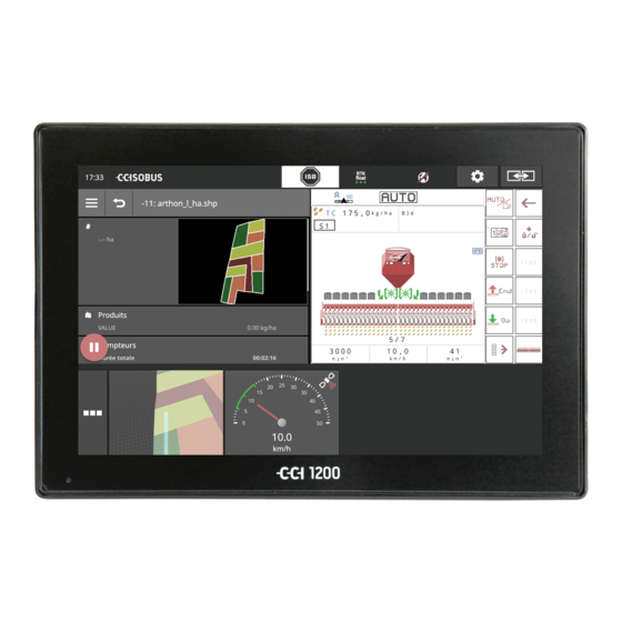
About the CCI 1200 We commend you on your purchase of this CCI 1200. The CCI 1200 is a manufacturer-independent operating terminal for controlling ISOBUS implements. The touchscreen of the CCI 1200 Is 12.1" in size and has a resolution of 1280x800 pixels, ... -
Page 8: Cci.apps
CCI.Apps The following CCI.Apps are installed on the CCI 1200: CCI.UT ISOBUS implement operation CCI.Cam Display of up to 8 cameras CCI.Config Implement settings CCI.Command Map view CCI.Control Data management CCI.Help Help system The following functions must be purchased separately and can only be... -
Page 9: Structure
Structure 1. 12.1" Touchscreen 2. Light sensor 3. ON/OFF button 4. 2x USB 2.0 5. ISOBUS, supply voltage, ECU-Power 6. Signal connector, GPS 7. Camera, video multiplexer 8. 2x USB 2.0 9. Ethernet 10. Buzzer The terminal is operated via the touchscreen. Common touch gestures Touchscreen are supported. - Page 10 Switch the terminal on or off using the ON/OFF button. ON/OFF Press the ON/OFF button for 1 second to switch it on or off. On some tractors and self-propelled implements, you can also switch the terminal on or off with the ignition key. The terminal switches off automatically, ...
- Page 11 Both USB interfaces on the left casing side are of type A. Standard flash drives can be connected. The USB interfaces on the rear side are type M12. These interfaces pro- tect the terminal against the penetration of dust and water, even when there is a connected USB device.
-
Page 13: Safety
Safety 1 Safety These operating instructions contain basic instructions which must be observed during setting up, configuration and operation. As such, it is absolutely essential to read these operating instructions prior to configu- ration and operation. Not only do the general safety instructions listed in the "Safety" chapter have to be observed but also the special safety instructions appearing in other chapters as well. -
Page 14: Intended Use
Safety Intended use The terminal is intended exclusively for use with approved ISOBUS im- plements and devices in agriculture. Any other installation or use of the terminal is not included within the manufacturer's area of responsibility. The manufacturer accepts no liability for any resulting personal injury or material damage. -
Page 15: Safety Instructions
Safety Safety instructions Warning - General Hazards! Please take special care to ensure the following safety instructions are complied with. Non-compliance could result in malfunctions and consequently danger for any bystanders: Switch the terminal off, if o the touch-screen does not react, o the display is locked or o the user interface is not properly displayed. -
Page 16: Installation Of Electrical Devices
Safety Installation of electrical devices Modern farming implements use electronic components and parts the operation of which can be compromised by electro-magnetic interfer- ence from other devices. Such effects can endanger people if the follow- ing safety indications are not observed. In the event of retrofitting electric and electronic devices, and/or com- ponents, in an implement with connection to the on-board network, the user must independently verify whether the installation interferes with... -
Page 17: Setting Up For Operation
Setting up for operation 2 Setting up for operation Setting the terminal up for operation is a quick and uncomplicated pro- cess based on the following step-by-step guide. Check the scope of delivery Check the scope of delivery of your terminal before you start setting up for operation: 1. -
Page 18: Install The Terminal
Setting up for operation Install the terminal The device holder is supplied with the terminal and is fitted on the ter- minal in the factory. Attach the terminal with the device holder to a 20mm diameter tube. Fit the terminal in landscape or portrait format. Note Mount the terminal so that it ... -
Page 19: Connect The Terminal
Setting up for operation Connect the terminal Connect the terminal to the ISOBUS and supply it with power via con- nector A: Connect cable A to connector A on the terminal and then to the in- cab panel connector of the tractor or the self-propelled implement. Switch on the terminal Press the ON/OFF button for 1 second. -
Page 20: Change Layout
Setting up for operation Change layout As supplied all operating screens are output in landscape format. If you have installed the device in portrait, then first change the layout: 1. Press the "Settings" button on the start screen. The "Settings" operating screen is displayed. 2. -
Page 21: Select Time Zone
Setting up for operation Select time zone The time zone forms the basis for the time displayed by the terminal. Switching between summer and winter time takes place automatically and cannot be disabled. Note Select the time zone with the correct time difference and the appropriate re- gion. -
Page 22: Enter Terminal Licence
Setting up for operation Enter terminal licence To be able to use all functions, you must enter the terminal licence for the terminal. The terminal licence can be downloaded from the web page https://sdnord.net/PA. 1. Press the "Settings" button on the start screen. ... - Page 23 Setting up for operation 7. Enter the TAN of the terminal and press the button "Start acti- vation...". The terminal licence is displayed: 8. On the terminal, press the "Next" button. The "Enter terminal licence" operating screen is displayed: 9.
- Page 24 Setting up for operation...
-
Page 25: Activate Apps
Setting up for operation Activate apps As supplied from the factory all apps, with the exception of CCI.UT2, are activated and ready for use. Activate CCI.UT2, if you want to simultaneously display and operate two ISOBUS implements in the Standard View. 1. -
Page 26: Setting Up The User Interface
Setting up for operation 2.10 Setting up the user interface When the terminal is first started, CCI.Help and CCI.UT are displayed in the Standard View You want to operate an ISOBUS implement with CCI.UT and record the Example implement data using CCI.Control. You have connected a camera to the terminal and want to keep the camera image visible during working: 1. -
Page 27: Graphical User Interface
Graphical user interface 3 Graphical user interface Familiarise yourself with the essential components and the layout of the screen content. Help CCI.Help supports you in your daily work with the terminal. CCI.Help Answers questions about operation based on experience, ... -
Page 28: Touch Gestures
Graphical user interface Touch gestures The terminal is operated using the touchscreen alone. The terminal sup- ports the following common touch gestures: Press Press briefly at the indicated point on the touchscreen. You se- lect an item in a selection list or trigger a function. Long press ... -
Page 29: Layout
Graphical user interface Layout During daily work with the terminal, you must be able to see all relevant information and operate several apps simultaneously. The terminal helps you to do so courtesy of it large size touchscreen and the flexible design of the user interface. Select a layout to match the terminal installation: Landscape Standard ... - Page 30 Graphical user interface Landscape Standard is described below. The descriptions can be applied to the other layouts. The display is divided into four areas: Display division Standard View Up to 2 apps are displayed in the Standard View. Mini View All active apps are displayed in the Mini View with the exception of the apps in the Standard View.
- Page 31 Graphical user interface Standard View Apps can only be operated if they are included in the Standard View. Mini View Apps in Mini View Cannot be operated, Only display the essential information, Continue running executing functions. From the fourth activated app, the Mini View extends to the right be- Scroll yond the visible area: ...
- Page 32 Graphical user interface Rearrange The arrangement of apps in Mini View can be changed: 1. Press and hold the app. The app visibly detaches from the Mini View. 2. Drag the app to the new position.
- Page 33 Graphical user interface App menu The app menu is in collapsed state. All apps that you have activated in App management are displayed in the app menu: Active apps Are displayed in Standard View, Mini View and in the app menu, ...
- Page 34 Graphical user interface Status bar The symbols in the information area of the status bar give an overview of the connection status and connection quality. Information area No signal No GPS receiver is connected. Invalid signal A GPS receiver is connected. However, the received position data are invalid.
- Page 35 Graphical user interface Buttons You have the following operating options: Use the ISB, If implement operation is not in the foreground, If you want to trigger several implement functions simultane- ously. Send an ISB command to all network members: ...
- Page 36 Graphical user interface Caution! Not all ISOBUS implements support the ISB function. Consult the implement operating instructions to see which implement functions of an implement are triggered by the ISB.
- Page 37 Graphical user interface In the event of a fault or if an operating error exists, a dialogue window Notifications is displayed with an error message. Before you can continue working, you must rectify the problem and acknowledge the message. The workflow is interrupted. After successful action, you receive feedback through messages in the status bar.
- Page 38 Graphical user interface Special buttons For efficient operation of the apps, the terminal provides special buttons. Action Button The Action Button provides direct access to the functions that are currently most important. Burger Button Open the Burger Menu using the Burger Button. The Burger Menu offers access to the settings, functions and help system of an app: ...
-
Page 39: Settings
Settings 4 Settings Press the "Settings" button. The "Settings" operating screen is displayed: Change the following settings directly in the "Settings" operating screen: Change screen brightness Push the control to the left to reduce the display brightness. ... - Page 40 Settings The settings are subdivided amongst the areas "User", "Layout", "Sys- tem", "Apps" and "Diagnostics". User Adjust the operating behaviour of the terminal: Sound and touch sound, Language and units and user administration. Apps Activate and configure apps: ...
-
Page 41: User Settings
Settings Diagnostics The terminal records a log. The log is only saved on the terminal and is not transmitted. If you are having problems operating the terminal or ISOBUS im- plement, you can send the log to your contact: 1. Connect a flash drive to the terminal. 2. - Page 42 Settings You have the following setting options: Volume The terminal and many ISOBUS implements issue audio warnings. The volume of the audio warnings can be adjusted: 1. Press the "Volume" button. The "Volume" operating screen is displayed. 2. Press the button with the percentage. ...
-
Page 43: App Settings
Settings App settings Press the "Apps" button in the "Settings" operating screen. The "Apps" operating screen is displayed: You have the following operating options: App settings Set up the apps. App management Activate and deactivate apps. See section App management ISOBUS settings Adjust the behaviour of the terminal on the ISOBUS. - Page 44 Settings App management Non-required apps can be permanently switched off. This has no effect on the available CPU power or the available RAM. Note It may occur that an action cannot be performed because an app is switched off. Therefore we recommend that, ...
- Page 45 You use CCI.Command on the CCI 1200 for Section Control. 1. In the ISOBUS settings on the CCI 1200, with the "Universal Termi- nal" off and the "Task-Controller" on. 2. In App management on the CCI 1200, switch CCI.UT1 off and...
- Page 46 Settings Adjust the behaviour of the terminal on the ISOBUS as follows: Press the "ISOBUS Settings" button in the "Apps" operating screen. The "ISOBUS settings" operating screen is displayed: If the ISOBUS function "Universal terminal" is activated, up to ...
- Page 47 Settings You do not want to operate any ISOBUS implement with the terminal. Switch "Universal Terminal" and the apps CCI.UT1 and CCI.UT2 off: 1. In the "ISOBUS settings" operating screen switch the "Univer- sal Terminal" "off". A message window is displayed. 2.
- Page 48 Settings Section Control, Rate Control and the recording of task data require the Task Controller ISOBUS function "Task Controller". The ISOBUS function "Task Controller" is activated ex works. The terminal registers on the ISOBUS as a "Task Controller". 1. Change to the operating screen "App settings". 2.
- Page 49 Settings You are using the Task Controller of the CCI 1200 and the Task Control- Task Controller Number ler of another ISOBUS terminal. Each of the two Task Controllers must have a unique number, as other- wise address conflicts on the ISOBUS may occur.
- Page 50 Settings You are using the task controller of another ISOBUS terminal. Switch "Task Controller" off: 1. Switch "Task Controller" "off". A message window is displayed. 2. Confirm your entry. The "Task Control" switch is "off". The terminal no longer registers on the ISOBUS as a "Task Controller".
- Page 51 The "TECU" ISOBUS function is activated ex works. The terminal registers on the ISOBUS as "TECU". Switch the TECU of the CCI 1200 off, if the TECU of the tractor displays an error message. 1. Switch the "TECU" "off".
-
Page 52: System Settings
Settings System settings Press the "System" button in the "Settings" operating screen. The "System" operating screen is displayed: You have the following operating options: Terminal data In terminal data, the version of the installed software and the se- rial number of the terminal are displayed together with other data. - Page 53 Settings CCI.OS-Update See section CCI.OS-Update Licence data See section Licence data Internet See section Internet agrirouter See section agrirouter Remote maintenance You cannot use remote maintenance; it is only available in test mode. Do not press the button.
- Page 54 Settings Date and time Note The terminal clock is very accurate and is set in the factory. You cannot and must not manually change the time. With an active Internet connection, the terminal adjusts the time based on a time server. ...
- Page 55 Settings Note The time and date are displayed in the selected format on the terminal and incorporated in the time stamp that the terminal sends over the ISOBUS. We recommend adherence to the factory settings. You have the following setting options: Select time zone Select the time zone with the correct time difference and the appropriate re- gion:...
- Page 56 Settings CCI.OS-Update The terminal software CCI.OS is constantly subject to further develop- ment and new functions are continuously being added. Your service partner will make new updates available to you as CCI.OS updates. Caution! During the update process, the terminal interrupts the connection to the ISO- BUS.
- Page 57 Settings Note Occasionally the update of CCI.OS may fail. Then the terminal can only be started in the rescue system. Create a backup, before you update CCI.OS. You have the following operating options: Update CCI.OS from the flash drive See section Update from the flash drive Update CCI.OS via the Internet Updating of CCI.OS via the Internet is only available in test mode...
- Page 58 Settings Update from Note the flash drive Use a flash drive with free space of at least 200MB. The installation program saves data on the flash drive for the duration of the update. Note The flash drive must remain connected to the terminal throughout the update! 1.
- Page 59 Settings Licence data The terminal licence data must be updated under the following circum- stances: Following a CCI.OS update, After acquisition of the licence for a paid-for function (e.g. Section Control or Parallel Tracking). Press the "Licence data" button. ...
- Page 60 Settings You have the following operating options: Update the licence data via the Internet This is the fastest and easiest update method. Use this function, if the terminal is connected to the Internet: 1. Press the "Internet" button. The licence data are updated. ...
- Page 61 Settings Internet The updating of the licence data can be performed quickly and easily via the Internet. You must have an active Internet connection for the agrirouter. You have the following options for connecting the terminal to the Inter- net: 1.
- Page 62 Settings You have the following operating options: Activate SmartConnect The SmartConnect is a multi-functional external add-on to the Ter- minal and provides, the Internet connection amongst other things: Connect the SmartConnect to the terminal. The terminal connects automatically to the SmartConnect. ...
- Page 63 Settings agrirouter Connect the terminal to agrirouter, to be able to receive or send tasks via the data exchange platform. Note You require an active Internet connection, so that agrirouter can receive and send tasks. It only takes a few steps to connect the terminal to agrirouter: ...
- Page 64 Settings 6. Enter the registration code. The code is case-sensitive. Confirm your entry with "Next". The "agrirouter" button can be pressed now. 7. Switch the "agrirouter" "on". An active connection is displayed in the information area. agrirouter set-up is completed. Note The registration code need only be entered once.
- Page 65 Settings Outbox The outbox contains all files which could not yet be sent to agri- router. Delete a file from the outbox as follows: 1. Press the "Outbox" button. The "Outbox" operating screen is displayed. 2. Press the button with the file names and keep the button pressed.
- Page 66 Settings Address registration service The Internet address of the registration service. You have received the registration code of the terminal from this registration service. Ex works, the registration service address is as follows https://cd- dke-data-hub-registration-service- hubqa.cfapps.eu10.hana.ondemand.com/api/v1.0/registra- tion/onboard/ . Only change the entry if you are requested to do so by agrirouter: 1.
-
Page 67: Display Of Camera Images
Display of camera images 5 Display of camera images CCI.Cam is used to display camera images. Maintain an overview of your implement and complex work processes with up to eight cameras. Cyclical camera changing makes manual switching between camera screens unnecessary. Open CCI.Cam in Standard View or Mini View. - Page 68 Display of camera images Connect two cameras To connect two cameras to the terminal, you require a video miniplexer. The video miniplexer is supplied with power from the terminal. The cameras are connected to the video miniplexer. Prior prepara- tion ...
- Page 69 Display of camera images Connect eight cameras You can connect up to eight cameras to the terminal using the video multiplexer. Caution! The video can only supply limited power to the video multiplexer. Overloading the power output will result in damage to the terminal. ...
- Page 70 Display of camera images Note Unassigned multiplexer connections output a black camera image.
-
Page 71: Operation
Display of camera images Operation Show camera image The camera image is displayed, if you open CCI.Cam in Standard View, Maxi View or Mini View. As with all apps, CCI.Cam can only be operated in Standard View or Maxi View. Mirror camera image The camera image is mirrored along the vertical axis. - Page 72 Display of camera images The functions described below must only be used if you have connected multiple cameras to the terminal. Show camera image continuously You want the image of a particular camera to be displayed. The camera image is to be displayed until you make another selection: 1.
- Page 73 Display of camera images Set automatic camera switching You want To switch automatically between some or all camera images and Specify the duration of display for each camera image. Change to editing mode: 1. Press centrally on the camera screen. ...
- Page 74 Display of camera images Start automatic camera switching: 9. Press centrally on the camera screen. The buttons for camera selection are displayed. 10. Press the red camera number with the "Stop" symbol. Automatic camera switching starts. The red button displays the "Play" symbol. Note If a camera image is not used for automatic camera switching, leave the cam- era off when selecting the sequence and display duration.
- Page 75 Display of camera images End automatic camera switching Automatic camera switching is turned on. You want to end automatic camera switching: 1. Press centrally on the camera screen. The buttons for camera selection are displayed. 2. Press the red camera number with the "Play" symbol. ...
-
Page 77: Implement Settings
Implement settings 6 Implement settings You want to use Section Control and Rate Control. Both functions are lo- cation-dependent and require accurate information about the tractor combination: the type and source of the speed information, the position of the GPS aerial and ... -
Page 78: Setting Up For Operation
Implement settings Setting up for operation An ISOBUS tractor makes the following tractor data available via the Tractor data ISOBUS to all network members: ground and wheel speed, PTO speed, direction of travel and position of the rear 3-point hitch. When the tractor is not connected to the ISOBUS, the terminal reads the Signal con- nector... -
Page 79: Tractor
Implement settings Tractor Note With a terminal fitted permanently on a tractor, only set up this tractor and then select it. If the terminal is used on various tractors, set up all tractors. Then if you change to another tractor, you need only select the correct tractor from the list. - Page 80 Implement settings Set up tractor Note If the distance C is not set, a warning symbol is displayed on the button next to the tractor name. Due to missing geometry data, Section Control cannot calcu- late the correct position. Set the distance C for all mounting types present on the tractor.
- Page 81 Implement settings Distance A 1. Fit the GPS aerial centrally on the tractor. This is the recom- mended procedure. 2. Press the button "Distance A". An input dialogue is displayed. 3. Set the distance A to 0. 4. End the Process with "Back". Distance A The distance between the GPS aerial and the tractor reference point: ...
- Page 82 Implement settings Distance B 1. Mark the mid-point of the rear axle and the position of the GPS aerial on the ground using chalk next to the tractor. 2. Measure the distance. 3. Press the button "Distance B". An input dialogue is displayed. 4.
- Page 83 Implement settings Mounting type and distance C 1. Check which mounting type the tractor has. 2. Measure distance C for each mounting type. 3. Press the button "Mounting type and distance C". A selection list is displayed. 4. Sequentially press the buttons of the mounting types and enter the measured distance C for this mounting type.
- Page 84 Implement settings Signal connec- Signal connector You do not require the signal connector if speed, PTO speed and position of the 3-point-hitch are available on the ISOBUS from the tractor TECU. Switch the signal connector "off". To read out the tractor data at the signal connector, proceed as follows: 1.
- Page 85 Implement settings You have the following setting options: Wheel speed Calibrate the wheel speed display. Ground speed Calibrate the ground speed display. Power take off speed You can find the number of pulses per power take off rotation from the tractor operating instructions. Enter the indicated value for the PTO speed: 1.
- Page 86 Implement settings Power management on/off Switch power management on or off. Press the "Power Management" button. The switch changes its position. Note Only switch Power Management on if an ISOBUS upgrade cable is fitted in the tractor, which provides this function.
- Page 87 Implement settings The list in the "Tractor" operating screen contains the tractor you have Select tractor created. Select the tractor on which the terminal is to be used: 1. Press the "Settings" button. The "Settings" operating screen is displayed: 2.
- Page 88 Implement settings The "Tractor" information area shows all the settings made: 1. Wheel speed 2. Ground speed 3. GPS speed 4. Power take off speed 5. Work position 6. Direction of travel 7. Mounting type and distance C2, reference point tractor - rear coupling point 8.
- Page 89 Implement settings Delete a tractor as follows: Delete tractor 1. Press the "Tractor" button in the "CCI.Config" operating screen. The list of tractors is displayed. 2. Press and hold the button with the tractor that you would like to delete. ...
-
Page 90: Implement
Implement settings Implement Add an implement: New implement 1. Press the "Settings" button. The "Settings" operating screen is displayed: 2. Press the "Apps" button. The "Apps" operating screen is displayed: 3. Press the "CCI.Config" button. The "CCI.Config" operating screen is displayed: 4. - Page 91 Implement settings Configure the implement: Set up imple- ment 1. Press on the arrow on the right side of the "Implement" button. The "Implement" information area pops up. 2. Press on the information area "Implement". The implement settings are displayed. 3.
- Page 92 Implement settings Implement type 1. Press the "Implement type" button The "Implement type" selection list is displayed. 2. Select the implement type. 3. End the Process with "Back". Implement type With trailed implements (2) and self-propelled implements (3), the position of the sections for curved tracks is calculated.
- Page 93 Implement settings Mounting type 1. Press the "Mounting type" button The "Mounting type" selection list is displayed. 2. Select the mounting type. 3. End the Process with "Back". Mounting type In the tractor settings you have entered a distance C for each possible tractor mounting type.
- Page 94 Implement settings Distance D1 1. Press the button "Distance D1" An input dialogue is displayed. 2. Enter the Distance D1 in metres. 3. End the Process with "Back". Distance D1 The distance between the coupling point and the implement reference point: ...
- Page 95 Implement settings Section geometry The following are displayed in the "Section geometry" operating screen: The values transferred from the implement and The delay times corrected on the terminal. Section geometry 1. Number of sections The numbering goes from left to right in the direction of travel. 2.
- Page 96 Implement settings Delay times Set the turn on delay and the turn off delay. Delay times The turn on delay time describes the time delay between the command and the application. During spraying, it is the time from the command "Turn on section" until the agent is applied.
- Page 97 Implement settings Set or correct delay times Some ISOBUS implements do not provide any delay times. This can be identi- fied in the "Section geometry" operating screen from the value "0" for the de- lay times. Set the delay times for such implements in the terminal. For other ISOBUS implements, the pre-set delay times are not applicable.
- Page 98 Implement settings The list in the "Implement" operating screen contains the Select imple- ment implements created by you and all ISOBUS implements with TC client that have already been con- nected to the terminal at least once. Select the implement, that is to be used for Section Control or Rate Con- trol: Note Carry out this procedure each time, if you want to attach or suspend a new im-...
- Page 99 Implement settings The "Implement" information area displays the following settings: 1. Working width 2. Number of sections 3. Distance A 4. Distance B 5. Distance E, implement reference point - midpoint of the sections 6. Distance D1, coupling point - implement reference point 8.
- Page 100 Implement settings Delete imple- Delete an implement as follows: ment 1. Press the "Implement" button in the "CCI.Config" operating screen. The "Implement" operating screen is displayed. 2. Press and hold the button with the implement that you would like to delete. ...
-
Page 101: Gps
Implement settings Set the position and interface of the GPS receiver. The data in the information area (1) is displayed, if a GPS receiver is connected and sending data and GPS source, interface and baud rate have been correctly selected. Note CCI.Command and CCI.Control have different requirements in respect of the accuracy of the position data of the GPS receiver. - Page 102 Implement settings You have the following setting options: GPS settings Position of the GPS aerial You specify whether the GPS aerial is attached on the tractor or the implement. 1. Press the button "Position of the GPS receiver". The "Position of the GPS aerial" selection list is displayed. 2.
- Page 103 Implement settings GPS source 1. Press the button "GPS source". The "GPS source" selection list is displayed. 2. Select the GPS source. 3. If you have selected "RS232 - serial", then define the serial in- terface and baud rate now. 4.
- Page 104 Implement settings If you have selected "RS232 - serial" as the GPS source, you must con- figure the serial interface: Serial interface Configure the connector to which you have connected the GPS re- ceiver or the serial output of the steering system. 1.
- Page 105 Implement settings Adjust GPS receiver Optimally configure the GPS receiver with a single click. This function is only available for the GPS receivers Hemisphere A100/101 and Novatel AgStar with serial interfaces. 1. Press the button "Adjust GPS receiver". The "Adjust GPS receiver" operating screen is displayed. 2.
-
Page 106: Cci.convert
Implement settings CCI.Convert When working with an N-sensor and an ISOBUS fertilizer, the application quantity should be automatically matched to the circumstances on the field. To do so, the sensor signal must be "translated" so that it is "un- derstood" by the fertilizer as a setpoint. CCI.Convert is this translator and converts the manufacturer-specific signals from N-sensors to implement-readable ISOBUS messages. - Page 107 Implement settings 6. Press the "Protocol" button. The "Protocol" selection list is displayed. 7. Select the sensor protocol. 8. Press the "Settings" button on the start screen. Setting up is ended. The "Settings" operating screen is closed. The settings can be changed at any time.
- Page 108 Implement settings Select implement Select the implement to which the sensor setpoints are to be sent. 1. Press the "Implement" button. The list of implements is displayed. 2. Select an implement or the option "Automatically select the im- plement". 3.
-
Page 109: Tacho
Implement settings Tacho Set up a tacho in CCI.Config: Displayed to the right alongside the tacho display is the tractor you have selected, the implement you have selected and the CCI.Convert settings Note Check whether the tractor and implement are correctly selected. ... - Page 110 Implement settings You have the following operating options: Select displayed value You select which value is to be displayed in the tacho: the wheel speed, the ground speed, the GPS Speed or the PTO shaft speed. 1.
- Page 111 Implement settings Set the optimum working range The optimum working range is displayed on the tacho in green. You can see at a glance whether a speed correction or PTO rpm correction is necessary. 1. Four values are displayed below the tacho. Press the second button from the left.
-
Page 113: Isobus
ISOBUS 7 ISOBUS ISOBUS implement You operate your ISOBUS implements with the terminal. Use the apps CCI.UT1 and CCI.UT2. Up to 5 ISOBUS implements can register on each of these universal terminals. However it is only ever possible to operate one of them. - Page 114 ISOBUS The operating screen of the ISOBUS auxiliary control is loaded and visi- ble. Implement functions are not yet assigned to the operating elements of the ISOBUS auxiliary control: Assign operating element Each operating element of the ISOBUS auxiliary control can be assigned any implement function.
- Page 115 ISOBUS Manufacturer of the ISOBUS auxiliary control ISOBUS auxiliary control List of operating elements 5. Switch "Editing mode" "on". All operating elements of the ISOBUS auxiliary control are dis- played in the selection list. Select an operating element. 6. Press the "+" in the operating element button. ...
- Page 116 ISOBUS 8. Press "Back" to return to the operating element selection list. The implement function is assigned to the operating ele- ment. The button displays the operating element and the imple- ment function. 9. To assign functions to other operating elements, repeat steps 2 to 4.
- Page 117 ISOBUS Check the assignments of the ISOBUS auxiliary control as follows: Checks 1. Open the operating screen of the ISOBUS auxiliary control in Standard View: 2. Change to the ISOBUS auxiliary control in all operating levels and check the assignment on the terminal. Note No changes to the AUX assignments can be made in the operating screen of the ISOBUS auxiliary control.
- Page 118 ISOBUS Delete assignment To delete the assignment of an individual operating element, proceed as follows: 1. Switch "Editing mode" "on". All operating elements of the ISOBUS auxiliary control are dis- played in the selection list. 2. Press the "-" in the operating element button. ...
- Page 119 ISOBUS Delete all assignments To delete the assignment of all operating elements, proceed as follows: 1. Switch "Editing mode" "on". 2. Press the button "Delete all AUX assignments". A message window is displayed. 3. Confirm your entry. The assignments of all operating elements are deleted. ...
-
Page 121: Data Management
Data management 8 Data management Data management with CCI.Control is subdivided into application areas Introduction Task management and documentation, Application maps. Setting up for operation CCI.Control is "on" in app management. Prior prepara- tion In the ISOBUS settings o the ISOBUS Task Controller function is "on"... - Page 122 Data management The settings can be changed at any time. You have the following setting Adjust CCI.Control options: Automatic export Automatic export protects against inadvertent deleting of task data. You have imported a task from the flash drive into the terminal and partially or completely processed it.
-
Page 123: Application Maps
Data management Application maps Shape import With CCI.Control you can import a shape application map and create a new task with it. Note A shape application map always comprises a number of files: .dbf, .shp, .shx and optional ... - Page 124 Data management Setpoint table The setpoint table of a shape application map contains one or more columns and the rows with the setpoints. When creating the shape application map, give the columns meaningful names. We recommend the use of product and unit, e.g. "Compost (t)". Unit selection when importing It is not apparent from a shape application map which units are to be used, i.e.
- Page 125 Data management The flash drive with the shape application map is connected to the Prior prepara- tion terminal. CCI.Control is displayed in the Standard View. 1. Press the Burger Button. The "Burger menu" is displayed. 2. Switch "Field mode" "off". 3.
- Page 126 Data management 9. Make a preselection. 10. Press the Action button. The selection list with the units is displayed. 11. Select the units. 12. Press the Action button. The shape application map is imported. The task is created and displayed.
-
Page 127: Map View
Map view 9 Map view CCI.Command is the detailed map view for use with Section Control and Introduction Rate Control. Using GPS, Section Control automatically switches off the sections of an ISOBUS implement upon passing over field boundaries and already treated areas and switches them back on upon leaving them. - Page 128 Map view You have the following setting options: Parallel Track- Overlapping 1. Press the "Overlapping" button An input dialogue is displayed. 2. Enter the overlap as a positive or negative value in centime- tres. 3. End the Process with "Back". Overlapping The overlap compensates for steering errors and position data inaccuracies.
- Page 129 Map view Lightbar The white segments of the lightbar indicate the deviation from the PT lane. Specify what deviation a segment of the lightbar represents. 1. Press the "Lightbar" button. An input dialogue is displayed. 2. Enter a value between 10 and 100 cm. 3.
- Page 130 Map view Degree of overlap Valid values for the degree of overlap are 0, 50 or 100%. 1. Press the "Degree of overlap" button. An input dialogue is displayed. 2. Enter the degree of overlap. 3. End the Process with "Back". Degree of overlap Specify with what covering a section is to be switched off if it overlaps an al- ready worked area.
- Page 131 Map view Overlap tolerance Values between 0 cm and half of the outer section are valid for the overlap tolerance. 1. Press the "Overlap tolerance" button. An input dialogue is displayed. 2. Enter the overlap tolerance. 3. End the Process with "Back". Overlap tolerance You work with a degree of overlap of 0%.
- Page 132 Map view Overlap tolerance in already worked areas You work with a degree of overlap of 100%. In runs over already worked areas (e.g. the headland) the outer sections may sometimes switch on in an undesired way. Causes for this are GPS drift or a track that has not been precisely followed. The overlap tolerance can prevent the unwanted switching on of the sections.
- Page 133 Map view Overlap tolerance at field boundary Values between 0 cm and half of the outer section are valid for the overlap tolerance. 1. Press the "Field boundary overlap tolerance" button. An input dialogue is displayed. 2. Enter the overlap tolerance. 3.
- Page 134 Map view Section Control only on/off in the headland Press the button "Section control only in the headland". The switch changes the position. Section control only in the headland When using seed drills and planters with very small sections (e.g. less than a meter) then with parallel tracks the result may be undesired switching off of the outer sections.
- Page 135 Map view Reverse gear detection 1. Press the "Reverse gear detection" button. The "Reverse gear detection" selection list is displayed. 2. Select the method for detecting reverse gear. 3. End the Process with "Back". Reverse gear detection The terminal detects the change in driving direction ...
-
Page 136: Troubleshooting
Troubleshooting 10 Troubleshooting Warning - behaviour in the event of technical failures Continuation of working after technical failures can result in damage to the ter- minal or the implement! 1. Stop working. 2. Look for a solution in this chapter of the operating instructions. 3. - Page 137 Troubleshooting If a hardware problem exists, the terminal switches off automatically. Blue flashing signals of the The LED of the ON/OFF button transmits a series of blue flashes. ON/OFF button The LED flashes once per second and, dependent on the error, 1 to 27 times in succession.
-
Page 138: Problems During Operation
Troubleshooting 10.1 Problems during operation This chapter lists problems that may occur during use of the terminal. A suggestion is made for rectification for each problem. If you cannot rectify the problem based on the suggestion, contact your dealer. Problem Cause/remedy The terminal does not switch The tractor does not switch off the supply to the in-cab con-... -
Page 139: Diagnostics
Troubleshooting 10.2 Diagnostics Screenshot A picture says more than a thousand words. If you are having problems operating the terminal or ISOBUS imple- ment, you can capture a screenshot and send it to your contact: A flash drive is connected to the terminal. Prior prepara- tion ... -
Page 140: Messages
Troubleshooting 10.3 Messages Messages indicate incorrect operation or an error state or allow you to interrupt the execution of a command. Messages are dialogue windows, interrupt the program flow and must be acknowledged. Each message is identified by a unique error number. 1. - Page 141 Troubleshooting Error Type/Message text/Remedy number 7035 Alert No flash drive connected. You want to export the event log. Saving of data on the flash drive has failed. Ensure that, the flash drive is connected to the terminal, the flash drive is functioning, ...
- Page 142 Troubleshooting Alert Exporting of the licence data has failed. 1. Ensure that a flash drive is con- nected. 2. Repeat the export. You want to update the licence data via flash drive. Saving of the TAN on the flash drive has failed. Ensure that, ...
- Page 143 Note: The UT with which you want to operate the AUX control, must receive the UT number 1. The error message appears if two UTs have the same UT number. Change the UT number of the UT on the CCI 1200 or on the other ISOBUS terminal.
- Page 144 Troubleshooting 51003 Alert The task data could not be imported. Did you remove the flash drive before the action was completed? Repeat the process and leave the flash drive plugged in until the process has completed. 51005 Alert The task data could not be exported. You want to Export Task Data.
- Page 145 Troubleshooting 51011 Alert The report could not be exported. Did you remove the flash drive before the action was completed? Repeat the process and leave the flash drive plugged in until the process has completed. 51013 Alert The task data could not be exported. Did you remove the flash drive before the action was completed? ...
- Page 146 Troubleshooting 54012 Alert There is no flash drive connected. If you have not connected a flash drive to the terminal: Connect a flash drive. If you have already connected a flash drive to the terminal: Use a different flash drive or a different USB port on the terminal. 56000 Caution The terminal is not connected with the ISOBUS.
-
Page 147: Glossary
Glossary 11 Glossary agrirouter A data exchange platform for farmers and contractors, with which implements and agricultural software can be connected independent of the software developer. agrirouter transports data but does not store it. Application map Section-specific setpoint map on which the quantity of product to be applied for each section in a field is specified, e.g. - Page 148 Glossary Panel connector Male connector permanently integrated in a device casing. Input dialogue Element of the graphical user interface. Enables the input or selection of values. FMIS Farm Management Information System Also: FMIS Software for yield data processing and the creation of application maps.
- Page 149 Glossary Implement Towed or attached implement. An implement with which a task can be executed. Agricultural practice Crop cultivation measure The action performed on a field such as tillage or ferti- lising. Miniplexer Device for switching between video signals which facil- itates operating of two cameras via one video input (similar to a multiplexer, but with limited functions).
- Page 150 Glossary Wheel speed sensor It emits a specific number of electrical signals in pro- portion to the wheel rotation. As such, the theoretical slip-including speed of the tractor, the wheel speed, can be calculated. Wheel based speed sensors may supply inaccurate speed values when slip occurs.
- Page 151 Such areas are then designated as sections. Section-specific working Satellite support use of an application map. Terminal The CCI 1200 terminal Touchscreen Touch-sensitive display for operation of the terminal. Uniform Resource Locator A standard used for website addressing in the World Wide Web;...
- Page 152 Glossary PTO sensor Measures the speed of the power take off. It emits a specific number of electrical pulses in pro- portion to the power take off speed. Extended Markup Language Logical markup language and both successor and en- hancement of HTML. XML permits the specification of its own language elements so that other markup lan- guages such as HTML or WML can be defined by using XML.
-
Page 153: Disposal
Disposal 12 Disposal Dispose of a defective or no longer used terminal with due care for the environment: Dispose of the device parts in an environmentally friendly manner. Observe the local regulations. Dispose of plastics with normal domestic waste or according to the local Plastics regulations. -
Page 154: Index
LED,flashes ......125 Camera image change automatically ....61 mirror ........59 Remote maintenance ....41 show continuously ..... 60 CCI 1200 About ........iii Safety instructions ......3 CCI.OS Scope of delivery ......5 updates ........44 Screen brightness Connector change ........ - Page 155 Index Status bar ........ 22...
-
Page 156: A. Technical Information
A. Technical Information Dimensions (B x H x D) [mm] 312 x 213 x 66 Casing Type Glass fibre reinforced polyamide Fastening VESA75 Operating Temperature [°C] -15 - +70 Supply voltage [V] 12 VDC or 24VDC Permitted Range [V] 7.5 VDC - 32VDC Power consumption (at 12V) [W] 17, typical 143, maximum... -
Page 157: B. Interfaces
B. Interfaces Caution! Connection or disconnection of a cable during live operation can cause damage to the terminal or peripheral. Switch the terminal off before connecting or disconnecting connector A, B or Caution! All terminal connectors are mechanically protected to prevent incorrect connec- tion or interchanging. - Page 158 Connector A Connector type Panel connector German DT, 12 pole, A-coded Function CAN1 CAN2 ECU power Power supply ISOBUS, switched ECU supply Signal Comment V+ in Supply voltage, 12VDC or 24VDC ECU Power enable Switched ECU supply voltage Power enable Switched supply voltage CAN_H...
- Page 159 Connector B Connector type Panel connector German DT, 12 pole, B-coded Function RS232 ISO 11786 Signal connector, GPS/LH5000/ADS/TUVR Signal Comment V+ out 12VDC or 24VDC ISO 11786, Ground based speed Ground speed sensor ISO 11786, Wheel based speed Wheel speed sensor ISO 11786, PTO speed Power take off speed...
- Page 160 Connector C Connector type Panel connector German DT, 12 pole, C-coded Function RS232 RS485 Video Camera, video miniplexer, video multiplexer, GPS/LH5000/ADS/TUVR Signal Comment V+ out Camera power supply Video IN Video GND Earth RS485B RS485A V+ out Supply voltage Video miniplexer or video multiplexer Not connected...
- Page 161 Connector 3 and 4 Connector type Socket M12, 5-pole, A-coded Function USB 2.0 Flash drive, W10 WiFi adapter Signal Comment Supply voltage Data - Data + Earth Earth Connector Eth Connector type Socket M12, 8-pole, X-coded Function Ethernet Signal Comment TR0+...
-
Page 162: C. Cable
C. Cable Note Where possibly only use and OEM cable to connect the terminal. You can order this from the manufacturer or its approved dealers. Identifier: Cable A Length: 150 cm "InCab": Coupling, 9-pole In-cab panel connector in the tractor "A": Coupling, 12-pole ... - Page 163 Identifier: Cable B Length: 30 cm "Signal": Coupling M12, 12-pole Cable H "Signal" "B": Coupling, 12-pole Connector B on the terminal "RS232": Coupling M8, 4-pole Peripheral Use: Connect terminal to signal connector and pe- ripheral using the serial interface Identifier: Cable C1 Length:...
- Page 164 Identifier: Cable C2 Length: 30 cm "Video": Coupling M12, 8-pole Camera "C": Coupling, 12-pole Connector C on the terminal "RS232": Plug M8, 4-pole Peripheral Use: Connect terminal to camera, video miniplexer or video multiplexer and peripheral using se- rial interface Identifier: Cable type H...
- Page 165 Identifier: Cable type N Length: 200 cm "NMEA": Plug, 9-pole GPS receiver "RS232": Coupling M8, 4-pole Plug "RS232" to cable B or C Use: Connecting the terminal to the GPS receiver Identifier: Cable Y Length: 15 cm "InCab": Coupling, 9-pole In-cab panel connector in the tractor "UT":...
-
Page 166: D. Application Maps
D. Application maps ISO-XML An application map in ISO-XML format may contain any approved DDI in the Data Dictionary. Percentage values can be processed. Grid type 1: max. 255 Zones Grid type 2: no limit Polygon: max. 255 Colours Up to 12 colours can be displayed in the legend Shape... -
Page 167: E. Time Zones
E. Time zones (UTC -09:00) Alaska (UTC -08:00) Tijuana, Baja California (Mexico) (UTC -08:00) Los Angeles, Vancouver (UTC -07:00) Chihuahua, Mazatlan (UTC -07:00) Denver, Salt Lake City, Calgary (UTC -07:00) Dawson Creek, Hermosillo, Phoenix ... - Page 168 Copyright ©2018 Competence Center ISOBUS e.V. Albert-Einstein-Str. 1 D-49076 Osnabrück Document number: 20180420...
Need help?
Do you have a question about the CCI 1200 and is the answer not in the manual?
Questions and answers
boundaries data was deleted after variable rate application