
Related Manuals for WoodFast BS450A


Summary of Contents for WoodFast BS450A
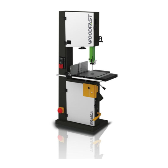
- Page 1 Instruction Manual BANDSAW BS450A IMPORTANT: For yoursafety,read instructions carefully before assembling or using this Original Instruction: product. Save this manual V.2-201910 for future reference.
- Page 2 INDEX GENERAL INFORMATION FOREWORD MACHINE IDENTIFICATION CUSTOMER SERVICE RECOMMENDATIONS SAFETY PRECAUTIONS SAFETY REGULATIONS RESIDUAL RISKS SAFETY AND INFORMATION SIGNALS SPECIFICATIONS MAIN COMPONENTS TECHNICAL SPECIFICATION ELECTRICAL CONNECTION NOISE LEVEL DUST EXTRACTION INSTALLATION INSTALLATION ZONE CHARACTERISTIC INSTALL OF LOOSE PARTS INTRODUCTION ADJUSTMENT AND OPERATION CENTERING TABLE AND TILTING SETTING TABLE SQUARE WITH BLADE CHANGING AND SETTING THE BLADE...
-
Page 3: General Information
1. GENERAL INFORMATION FOREWORD This machine is professional for straight cutting and square cutting of wood material, especially for wood panels cutting. Some information and illustrations in this manual may differ from the machine in your possession, since all the configurations inherent in the machine complete with all the optional are described and illustrated. - Page 4 - The working area around the machine must be kept always clean and clear, in order to have an immediate and easy access to the switchboard. - Never insert materials which are different from those which are prescribed for the machine utilization. - Never process pieces which may be too small or too wide to the machine capacity.
- Page 5 WARNING Manufacturer got no responsibilities for accidents caused by electrical parts to be connected to the machine by unqualified personnel and incorrect installation. WARNING Manufacturer got no responsibilities for accidents caused by changing machine function or spare parts arbitrarily by users or any person. WARNING Manufacturer got no responsibilities for accidents caused by operation under missing parts or damage condition of the machine.
-
Page 6: Main Components
4-Lower wheel 12-Dust port 5-Miter guage 13-Motor 6-Table 14-Rip fence 15-Blade tension knob 7-Blade guard 16-Quick tension handle 8-Lifting knob TECHNICAL SPECIFICATION SPECIFICATION BS450A Motor voltage 220-240V/50Hz Power Blade length 3886mm Blade width 6-35mm Max. cut depth 330mm Throat width 445mm... -
Page 7: Electrical Connection
3.3 ELECTRICAL CONNECTION - Electrical installation should be carried out by competent, qualified personnel. - The mains connection should be made using the terminal box. - Replacement of the power supply cable should only be done by a qualified electrician. WARNING To avoid electrocution or fire, any maintenance or repair to electrical system should be done only by qualified electricians using genuine replacement parts. -
Page 8: Installation Zone Characteristics
4. INSTALLATION INSTALLATION ZONE CHARACTERISTICS WARNING It is prohibited to install the machine in explosive environments. The installation zone must be selected evaluating the work space required depending on the dimension of the piec es to be machined, and taking into account that a free space of at least 800mm must be left around the machine. It is also necessary to check the floor capacity and its surface, so that the machine base is evenly resting on its four supports. -
Page 9: Adjustment And Operation
5. ADJUSTMENT AND OPERATION WARNING Handle the tools with protective gloves. CENTERING TABLE AND TILTING - Centering table can be adjusted. Loosen the four bolts which hold the lower table trunnion, and adjust freely. Place the blade in the middle of the faucet and make it be parallel to the slotted side of table. -
Page 10: Troubleshooting
SETTING CUTTING HEIGHT - The upper blade guide should always be set as close as practical against the work. To adjust, loosen the clamp handle B, rotate handle A to adjust upper guide close to material, tighten handle B. 6. TROUBLE SHOOTING Fig.5.5 WARNING - For any information or problem contact your area dealer or our technical service center. -
Page 11: Parts Diagram
PARTS DIAGRAM... -
Page 12: Parts List
PARTS LIST FRAME ASSEMBLY D 040V 1-JMBS1801010009-040V Switch plate 1-LA39-B2-10-g Switch on 1-LA39-B2-01-r Switch off 1-LA39-B2-R02Z-R Emergency switch 818D1Z B 117T 001S 1B 117T 1-M4X30GB819D1Z 4X30 Switch 1-QKS7 1-M6X12GB70D1Z Hex socket cap screw M6X12 040V Switch plate 1-JMBS1402010002 1-M4GB6170Z 1-WSH4GB862D2Z 1-LA42J Q T -02F Foot switch 1-JL20072003... - Page 13 PARTS DIAGRAM TABLE ASSEMBLY NOTE: Please reference the Manufacturer’s Part Number when calling for Replacement Parts. For Parts under Warranty, the serial number of your machine is required.
- Page 14 PARTS LIST TABLE ASSEMBLY 1-JMBS1801030002A-001U Extension table...
- Page 15 PARTS DIAGRAM GUIDE POST ASSEMBLY NOTE: Please reference the Manufacturer’s Part Number when calling for Replacement Parts. For Parts under Warranty, the serial number of your machine is required.
- Page 16 PARTS LIST GUIDE POST ASSEMBLY 126T...
- Page 17 PARTS DIAGRAM BLADE TENSION & TRACKING NOTE: Please reference the Manufacturer’s Part Number when calling for Replacement Parts. For Parts under Warranty, the serial number of your machine is required.
-
Page 18: Blade Tension & Tracking
PARTS LIST BLADE TENSION & TRACKING NOTE: Please reference the Manufacturer’s Part Number when calling for Replacement Parts. For Parts under Warranty, the serial number of your machine is required. -
Page 19: Parts Diagram & Parts List
PARTS DIAGRAM & PARTS LIST RIP FENCE ASSEMBLY NOTE: Please reference the Manufacturer’s Part Number when calling for Replacement Parts. For Parts under Warranty, the serial number of your machine is required. 001U... - Page 20 PARTS DIAGRAM & PARTS LIST MOTOR & DRIVE WHEEL ASSEMBLY 001L NOTE: Please reference the Manufacturer’s Part Number when calling for 1-JMBS1801020002C Replacement Parts. 001L For Parts under Warranty, the serial number of your machine is required.
-
Page 21: Pedal Assembly
PARTS DIAGRAM & PARTS LIST PEDAL ASSEMBLY 1-M10X35GB5783Z Hex head bolt Washer 1-WSH6GB96D1Z Connecting rod 1-JXBS1804013001A-040V 1-M12GB6172D1Z 1-M10GB6172D1Z Hex head bolt NOTE: Please reference the 1-M8X25GB70D1Z Washer Manufacturer’s Part Number 1-WSH8GB97D1Z when calling for Brake block 1-JXBS1804013100 Replacement Parts. Hex head bolt 1-M6X20GB5783Z Spring 1-FDPT1202020021...
Need help?
Do you have a question about the BS450A and is the answer not in the manual?
Questions and answers
How do I reset the foot switch so saw will turn on again?