
Related Manuals for KUHN FC244R


Summary of Contents for KUHN FC244R
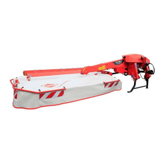
- Page 1 Operator's manual KN330CGB_A Read carefully before starting the machine Mower conditioner Original instructions - English - 06-2019 KN330CGB_A...
-
Page 3: Dear Owner
1. Dear Owner In buying a Kuhn machine you have chosen wisely. Into it have gone years of thought, research and improvement. You will find, as have thousands of owners all over the world, that you have the best that engineering skill and actual field testing can produce. -
Page 4: Table Of Contents
Mower conditioner FC244R / FC244R HD 2. Contents Dear Owner ........................3 Contents ..........................4 Identification of the machine..................8 Front view ............................8 Rear view ............................8 Identification of the machine ......................9 3.3.1 Location of the plates ......................9 3.3.2 Description.......................... 9 Optional equipment.........................11... - Page 5 Mower conditioner FC244R / FC244R HD Location and description of safety decals on the machine ............28 4.3.1 Location of safety decals....................28 4.3.2 Description of safety decals ..................... 29 Road safety equipment and recommendations ................32 4.4.1 Specific instructions......................34 Likely critical failures........................
- Page 6 Mower conditioner FC244R / FC244R HD Instructions for work....................59 Putting the machine into work position ..................59 Adjustments in working position..................... 61 8.2.1 Cutting height ........................61 8.2.2 Ground pressure....................... 62 8.2.3 Conditioning intensity ....................... 66 8.2.4 Swath width adjustment....................67 Machine use ..........................
- Page 7 Mower conditioner FC244R / FC244R HD 10.5 Storage ............................110 10.5.1 At the end of each season....................110 10.5.2 At the start of each season....................111 10.5.3 Storage ..........................113 10.6 Dismantling and scrapping of the machine...................113 11. Troubleshooting guide ....................114 12. Appendix........................120 12.1...
-
Page 8: Identification Of The Machine
Mower conditioner FC244R / FC244R HD 3. Identification of the machine Front view Rear view 3. - Identification of the machine KN330CGB_A... -
Page 9: Identification Of The Machine
3.3.1 Location of the plates - Please write below the type and serial number of the machine. • Serial Number: - This information is to be given to the Kuhn authorized dealer for any spare parts order or warranty claim. 3.3.2 Description ... - Page 10 Mower conditioner FC244R / FC244R HD Certification plate (CE) For machines aimed at countries which are 26: Model Year members of the European Union (EC marking). 24: Year of Construction 7: Model KUHN logo 9: Serial Nr. Model Machine serial number...
-
Page 11: Optional Equipment
Mower conditioner FC244R / FC244R HD Optional equipment - Tick box corresponding to the equipment fitted on your machine: Raised skid shoes 120 mm (4.7’’). Swath shield extensions. Shut off valve. Lateral signalling equipment (For: France, Belgium). -
Page 12: Safety
Mower conditioner FC244R / FC244R HD 4. Safety Description of symbols used in this document This symbol indicates a potentially hazardous situation that if not avoided, could result in serious bodily injury. This symbol is used to identify special instructions or procedures which, if not followed strictly, could result in machinery damage. -
Page 13: Safety Instructions
Mower conditioner FC244R / FC244R HD Safety instructions 4.2.1 Introduction The machine must only be operated, maintained and repaired by competent persons who are familiar with machines' specifications and operation and aware of safety regulations for preventing accidents. The operator must imperatively respect safety instructions in this manual and in the warnings posted on the machine. -
Page 14: Precautions To Take Before Using The Machine
Mower conditioner FC244R / FC244R HD 4.2.4 Precautions to take before using the machine Do not wear loose clothing which could become caught up in moving parts. Wear the appropriate protective clothing for the work in hand (gloves, shoes, goggles, helmet, ear defenders, etc.). -
Page 15: Precautions When Driving
Mower conditioner FC244R / FC244R HD 4.2.5 Precautions when driving Tractor handling, stability, performance and braking efficiency are all affected by weight distribution, trailed or mounted implements, additional ballast and driving conditions. It is therefore of great importance that the operator exercises caution in every given situation. - Page 16 Mower conditioner FC244R / FC244R HD Lights and indicators Before transporting the machine on public roads, ensure that all legally required lightings and signallings are in place. Ensure that lightings and signallings are clean and in good working order. Replace any missing or broken equipment.
- Page 17 Mower conditioner FC244R / FC244R HD Description of symbols Description Units Description Tractor unladen weight PTAC Gross Combined Weight Rating Unladen load on tractor front axle Empty load on tractor rear axle Axle loads (Tractor + machine) Load on front axle (Tractor + machine)
- Page 18 Mower conditioner FC244R / FC244R HD Stage 2: - Couple the machine to the tractor. To measure: - Load on front axle (t1): • Tractor + machine (transport position). To do: - If the front axle load (t1) is below 20% of the tractor tare (T), add ballast weights (M1) to exceed the minimum load on the front axle.
-
Page 19: Maximum Speed
Mower conditioner FC244R / FC244R HD Stage 4: To measure: - Load on rear axle (t2): • Tractor + machine (transport position). • Ballast weights. kg kg Checking: - Check in the tractor's operator's manual that the value measured is below the maximum allowed tractor rear axle load. -
Page 20: Hydraulic Circuit
Mower conditioner FC244R / FC244R HD 4.2.9 Hydraulic circuit Caution! The hydraulic circuit is under high pressure. Maximum pressure at work: 200 bar (2901 psi). Before connecting hoses to the tractor hydraulics, ensure that tractor and machine circuits are not under pressure. -
Page 21: Pto Shaft
Mower conditioner FC244R / FC244R HD 4.2.10 PTO shaft Use only PTO shafts supplied with the machine or recommended by the machine manufacturer. The protective shield of the tractor PTO stub, the PTO shaft guards and the protective shield of the machine input shaft must always be in place and in good condition. - Page 22 Mower conditioner FC244R / FC244R HD Before engaging the PTO drive, make sure that there are no people or animals near the machine. Never engage the PTO drive when the tractor engine is stopped. Do not install any adapter device that results in a portion of the tractor PTO stub, the rotating PTO shaft, or the adapter to be unguarded.
-
Page 23: Precautions During Manoeuvres
Mower conditioner FC244R / FC244R HD 4.2.11 Precautions during manoeuvres When moving the machine from the transport position to the working position and vice versa, make sure that nobody is within the machine pivoting area. 4.2.12 Remote controlled components Danger of crushing and shearing can exist when components are operated by hydraulic or pneumatic controls. -
Page 24: Safety Decals
Mower conditioner FC244R / FC244R HD 4.2.14 Safety decals Safety warning decals are placed in pictorial form on various parts of the machine. They are there to warn you of potential dangers and to tell you how to avoid accidents. -
Page 25: Precautions For Maintenance And Repair Work
For your own safety and for correct machine operation, only use original manufacturer parts. It is strongly recommended to have your machine checked by your Kuhn dealer after each season, especially tools and their attaching hardware. 4. - Safety KN330CGB_A... - Page 26 Mower conditioner FC244R / FC244R HD 4.2.17 Projection of stones and foreign objects - For driver safety, always use a tractor equipped with a cab. Keep the ground to mow free of foreign bodies. Avoid mowing on stony or rocky grounds.
-
Page 27: Precautions To Take Before Using The Parking Stands
Mower conditioner FC244R / FC244R HD 4.2.18 Precautions for machine use After each use, check the cutting tools (discs, knives) their attachment hardware accordance with the instructions given in the present manual. Immediately replace any worn, damaged or missing cutting tool or element. To do this, use the tool outfit supplied with the machine. -
Page 28: Location And Description Of Safety Decals On The Machine
Mower conditioner FC244R / FC244R HD Location and description of safety decals on the machine 4.3.1 Location of safety decals K9A144CE 0 4. - Safety KN330CGB_A... -
Page 29: Description Of Safety Decals
Mower conditioner FC244R / FC244R HD 4.3.2 Description of safety decals Operating instructions (1) The operators' manual contains all the information necessary for using the machine safely. It is imperative to read and comply with all instructions. Working on the machine (2) - Page 30 Mower conditioner FC244R / FC244R HD Projections (3) Stones and other debris projected by the moving parts can travel a long distance. The protection covers must always be in position and in good condition. Always stay at a safe distance from the machine.
- Page 31 Mower conditioner FC244R / FC244R HD Rotating cutting tools (6) Keep away from the mower knives all the time the engine is running, the PTO drive engaged and the moving parts have not come to a complete stop. ...
-
Page 32: Road Safety Equipment And Recommendations
Road safety equipment and recommendations The road safety equipment is mounted in the factory or by your authorized Kuhn dealer according to current safety regulations. - Always keep to the legal speed limit for driving a tractor-machine assembly on public roads. - Page 33 Mower conditioner FC244R / FC244R HD • A signalling light (1). • A signalling panel (2). • 2 red reflectors (3). The side device is made up of the following components: • 2 amber reflectors (1) on each machine side.
-
Page 34: Specific Instructions
Mower conditioner FC244R / FC244R HD 4.4.1 Specific instructions Lateral signalling equipment Instructions specific to the following countries: • France. • Belgium. To conform with the current road regulations, the machine must be fitted with specific signalling panels when driving on public roads. -
Page 35: Incorrect Use Of The Machine By The User
Mower conditioner FC244R / FC244R HD Incorrect use of the machine by the user 133996: Specific requirements for countries member of the Eurasian Economic Community (EAC marking): • 133998: Specific requirements for countries member of the Eurasian Economic Community (EAC marking). -
Page 36: Machine Specifications
Mower conditioner FC244R / FC244R HD 5. Machine specifications Description and glossary Parking stand Lift pump Hydraulic valve Pressure gauge Connecting frame Hitch pin Cutterbar Central gearbox Swath shield 10 : Lift/compensating cylinder 11 : Hydro-pneumatic accumulator 12 : Conditioning rollers... -
Page 37: Designated Use Of The Machine
5.1.1 Designated use of the machine The FC244R /FC244R HD mower conditioner must only be used for the work for which it has been designed: mowing on the ground of hay fields, grass silage fields and improved pastures for the purpose of harvesting fodder for feeding livestock. -
Page 38: Required Equipment
Mower conditioner FC244R / FC244R HD Required equipment 5.3.1 Cutter bar Knife attachment per bolt and nut: • Standard. • "HD" discs. 5. - Machine specifications KN330CGB_A... -
Page 39: Hydraulic Adjustment
Mower conditioner FC244R / FC244R HD 5.3.2 Hydraulic adjustment Valve adjusted using the 18 box wrench supplied with the machine. Sound levels Sound levels have been measured in accordance with the measuring methods as defined in: • NF EN ISO 4254-1 «Agricultural machinery - Safety - Part 1: General requirements»... -
Page 40: Putting Into Service
Mower conditioner FC244R / FC244R HD 6. Putting into service Description of control elements The machine is fitted with a release cord operated from the tractor cab. The machine is supplied with a wrench of 18 (1) and an hexagonal wreanch (2) of 8 mm (0.31’’) to carry out some adjustment and maintenance tasks. -
Page 41: Coupling And Uncoupling
Mower conditioner FC244R / FC244R HD Front guard release: - Pull handle (1) to unlock front guard. - Raise front guard until lock is automatically engaged. Front guard locking: - Pull handle (1) to unlock front guard. - Lower front guard until lock is automatically engaged. -
Page 42: Description Of Coupling Elements
Mower conditioner FC244R / FC244R HD 6.2.1 Description of coupling elements • (1): A PTO shaft. • (2): A release cord. • (3): Two hydraulic hoses which control the machine transport/work position setting. • (4): 1 hydraulic hose pressurizing the machine's ground pressure adjustment system (To adjust). - Page 43 Mower conditioner FC244R / FC244R HD The tractor must be fitted with lower link stabilizers. - Check that stabilisers function properly: • Locking. • Unlocking. • Adjustment. - Select the tractor speed of 540/min. The tractor must be equipped with: •...
-
Page 44: Preparing The Machine
Mower conditioner FC244R / FC244R HD Lateral adjustment of the lower links - Balance the play on either sides of the lift linkage and lock lower link stabilizers. - Check that the stabilisers function properly (Adjustment, Locking / Unlocking). - Page 45 Mower conditioner FC244R / FC244R HD If measure A is below 2.20 m (7’3’’): - Place lower links in position (b). Refer to the decal fitted on the machine. K9C472TL 0 K9C472TL 0 6. - Putting into service KN330CGB_A...
- Page 46 Mower conditioner FC244R / FC244R HD Do not couple machine as in (c) or (d). The tractor lift arms risk deteriorating the frame after several maneuvers. 6. - Putting into service KN330CGB_A...
-
Page 47: Coupling The Machine
Mower conditioner FC244R / FC244R HD 6.2.4 Coupling the machine - Insert the 2 ball joints of the tractor on the machine’s hitch pins. Preferably use cone guide pins (1). - Secure each hitch pin with lynch pin. - Lower the tractor three-point linkage. -
Page 48: Hydraulic Connections
Mower conditioner FC244R / FC244R HD - Lift the machine using the tractor lift linkage until the parking stand no longer rests on the ground. - Remove lynch pin (1). - Pull lock (2) (a). - Raise parking stand (b). -
Page 49: Electrical Connections
Mower conditioner FC244R / FC244R HD After making the connections, check that there is no risk of the hoses being caught during operation. 6.2.6 Electrical connections - Connect 7-pin plug to the tractor. 6.2.7 Primary PTO shaft Before using the machine for the first time: - Grease the transmission. - Page 50 Mower conditioner FC244R / FC244R HD - Separate the two half PTO shafts and connect them to the machine's input shaft and to the tractor PTO stub. - Check the length of the PTO shaft: • When the PTO shaft is in its maximum overlap position (retracted), tubes should not butt against the yokes.
-
Page 51: Intermediate Pto Shaft
Mower conditioner FC244R / FC244R HD Never operate the PTO shaft at an angle X exceeding 30°. To avoid serious accidents, the PTO drive shaft guards must be properly in place and fixed with the chains provided. - On machine side, attach chain around the pto shaft support located between the top link yoke. - Page 52 Mower conditioner FC244R / FC244R HD Before using the machine for the first time: - Grease the transmission. See section: Maintenance and storage / Lubrication / PTO shaft. The intermediate PTO shaft is fitted with a friction slip clutch Before the machine is put into service and...
-
Page 53: Adjusting The Machine
Mower conditioner FC244R / FC244R HD 6.2.9 Adjusting the machine Positioning of lower links: - Measure dimension E. - Adjust the side stabilizers of the tractor's lower links to obtain a measure E of 50 mm (2"). Frame height... -
Page 54: Uncoupling The Machine
Mower conditioner FC244R / FC244R HD Refer to the decal fitted on the machine to check the distance between the right hitch pin and the ground. When optional equipment is used, follow specific procedures mentioned in the related section: 500 mm 20 in •... - Page 55 Mower conditioner FC244R / FC244R HD - Uncouple the PTO shaft. - Place PTO shaft in its support (1). - Disconnect the hydraulic hoses (2). - Disconnect electric signalling plug (3). - Place hydraulic hoses and electric signalling plug in their respective supports.
-
Page 56: Instructions For Transport
Mower conditioner FC244R / FC244R HD 7. Instructions for transport Before placing the machine into transport position: - Wait until the rotating parts have come to a complete stop. - Check that nobody is located in the machine pivoting area. If there is someone, make sure the person moves away. - Page 57 Mower conditioner FC244R / FC244R HD The pressure indicated on the pressure gauge must be below 140 bar (2031 psi). Never engage the tractor PTO drive when the machine is in transport position. If the intermediate PTO shaft torque limiter...
-
Page 58: Conformity With The Road Regulations
Mower conditioner FC244R / FC244R HD Conformity with the road regulations Before driving the machine on public roads, ensure that the machine complies with current highway code regulations. - Check that the signalling panel is clean and that the lighting equipment functions before going on public roads. -
Page 59: Instructions For Work
Mower conditioner FC244R / FC244R HD 8. Instructions for work Before placing the machine in working position: - Check that nobody is within the machine pivoting area. - If there is someone, make sure the person moves away. Putting the machine into work... - Page 60 Mower conditioner FC244R / FC244R HD If the tractor is fitted with an adjustable hydraulic valve, select a high flow for a gradual machine opening without contact with the ground. - Lower the tractor lift to obtain a distance of H = 500 mm (1’8’’).
-
Page 61: Adjustments In Working Position
Mower conditioner FC244R / FC244R HD Adjustments in working position 8.2.1 Cutting height The desired cutting height is obtained directly by adjusting the top link length. This height is adjustable between 30 and 80 mm (1.2’’ - 3.1’’) depending on the tractors. -
Page 62: Ground Pressure
Mower conditioner FC244R / FC244R HD 8.2.2 Ground pressure The ground pressure adjustment determins the safety breakback adjustment. Example: increasing the pressure on the pressure gauge reduces the mowing unit ground pressure and increases the release force. The mowing unit suspension is obtained by a hydro- pneumatic accumulator. - Page 63 Mower conditioner FC244R / FC244R HD To check the ground pressure - Place the machine in headland turn position. - Check that the chassis height is correct: • Lower the tractor lift to obtain a distance of H = 500 mm (1’8’’).
- Page 64 Mower conditioner FC244R / FC244R HD Setting the ground pressure of the mowing unit The following adjustments do not cause the machine to move. - Place the machine in working position. - Connect hydraulic hose (1) of the floatation system to a single acting valve.
- Page 65 Mower conditioner FC244R / FC244R HD - When the required pressure is reached, close the valve. - Place the tractor single acting valve in floating position. - Disconnect and store hydraulic hose in holder (1). The valve must only be in open position for pressure adjustments.
-
Page 66: Conditioning Intensity
Mower conditioner FC244R / FC244R HD 8.2.3 Conditioning intensity - Before leaving the tractor or before adjusting, maintaining or repairing the machine, disengage the PTO drive, turn off the engine, remove ignition key and wait until all moving parts have come to a complete stop and apply park brake. -
Page 67: Swath Width Adjustment
Mower conditioner FC244R / FC244R HD 8.2.4 Swath width adjustment The swath width is adjustable from 0.90 m (2’11’’) to 1.80 m (5’10’’) approximately. - Loosen the 2 wing nuts (1) of the swath shields. - Perform the required adjustment. -
Page 68: Drive Speed
Mower conditioner FC244R / FC244R HD 8.3.1 Drive speed Adapt the forward speed to the working conditions. 8. - Instructions for work KN330CGB_A... -
Page 69: Optional Equipment
Mower conditioner FC244R / FC244R HD 9. Optional equipment Raised skid shoes The raised skids shoes allow mowing higher, between 60 and 120 mm (2.4’’ - 4.7’’). - Replace the end disc skids by the 2 raised skid shoes. raised... -
Page 70: Flow Limiter
Mower conditioner FC244R / FC244R HD Flow limiter This equipment allows adjusting the mowing unit travel speed when switching from the headland turn position to the work position. - Loosen screw (1). - Turn adjustment knob (2) clockwise to reduce de tractor valve oil flow. -
Page 71: Female Coupler
Mower conditioner FC244R / FC244R HD Female coupler USA signalling equipment 9.6.1 Coupling and uncoupling Electrical connection - Connect 7-pin plug to the tractor. Removal Disconnect and store 7-pin plug in its holder. 9. - Optional equipment KN330CGB_A... -
Page 72: Chain Stroke Limiter
Mower conditioner FC244R / FC244R HD Chain stroke limiter This equipment enables adjusting the chassis height in the absence of a hydraulic stroke limiter with position indexation on the tractor. Fit the chain stroke limiter on the machines: - Place the machine in headland turn position. - Page 73 Mower conditioner FC244R / FC244R HD - Lower the tractor lift to obtain a distance of H = 500 mm (1’8’’). - Measure distance H between the right hitch pin and the ground. - Refer to the decal fitted on the machine to check the distance between the right hitch pin and the ground.
-
Page 74: Maintenance And Storage
Mower conditioner FC244R / FC244R HD 10. Maintenance and storage - Before adjusting, maintaining or repairing the machine, turn off ignition key and wait until all moving parts have come to a complete stop. 10.1 Frequency chart Maintenance intervals are indicated for normal conditions of use. -
Page 75: Cleaning The Machine
Mower conditioner FC244R / FC244R HD Grease: - The mowing unit lift cylinder ball joint. - The control lever pin. - The mowing unit pivot pin. - The cutterbar connecting frame pivot pin. - The control pivot pin. -
Page 76: Lubrication
Mower conditioner FC244R / FC244R HD - Regularly clean the build up between the conditioning hood and the support tube: - Remove the split pins on both tube ends. - Remove the rear part of the protection cover. - Clean and reassemble the unit. - Page 77 Mower conditioner FC244R / FC244R HD Primary PTO shaft Every 100 hours: • universal joints (1). • transmission tube (2). • Guide rings (3). Before using the machine for the first time: - Grease the transmission. In intensive use, it is recommended to proceed with greasing at closer intervals: •...
-
Page 78: Oil Change
Mower conditioner FC244R / FC244R HD - Place the machine in working position. - Stop the tractor engine and remove ignition key. The U-joint grease zerks of the intermediate PTO shaft are accessible through openings 2 on the guard cones (1): - If necessary, rotate a disc to access the grease zerk. - Page 79 Mower conditioner FC244R / FC244R HD - Never use an oil of viscosity SAE 90 in the cutterbar. From the transport position: - Unlock and raise front guard. - For safety reasons, hook check chain as high as possible. - Remove the inner skid shoe (1) on drive side.
- Page 80 Mower conditioner FC244R / FC244R HD When changing the oil, it is recommended to use either an identical mineral oil or a synthetic oil of type PAO (Poly-Alpha-Olefine) with viscosity grade SAE75W90 - Remove dipstick plug (1). - Place a container of sufficient capacity under drain plug.
-
Page 81: Lubrication
Mower conditioner FC244R / FC244R HD When changing the oil, it is recommended to use either an identical mineral oil or a synthetic oil of type PAO (Poly-Alpha-Olefine) with viscosity grade SAE75W90 - Remove the filler plug (1). - Place a container of sufficient capacity under drain plug. -
Page 82: Greasing
Mower conditioner FC244R / FC244R HD • Roller drive chain. To lubricate the chain: • Lubricate chain with SAE80W90 GL5 oil through opening (1). 10.3.4 Greasing - Lubricate with multi-purpose grease grade NLGI 2. • The mowing unit lift cylinder ball joint. - Page 83 Mower conditioner FC244R / FC244R HD • The mowing unit pivot pin. • The cutterbar connecting frame pivot pin. • The control pivot pin. 10. - Maintenance and storage KN330CGB_A...
- Page 84 Mower conditioner FC244R / FC244R HD • Roller bearing housings: - Remove 3 bolts (1). - Remove chain guard (2). - Grease roller bearing housing on chain drive side (3). - Remove 3 bolts (1). - Remove belt guard (2).
-
Page 85: Maintenance
Mower conditioner FC244R / FC244R HD 10.4 Maintenance - Before adjusting, maintaining or repairing the machine, turn off ignition key and wait until all moving parts have come to a complete stop. 10.4.1 Hydro-pneumatic accumulator - Prior to carrying out work on a circuit... -
Page 86: Transport Stop
The transport stop (1) limits the machine's oscillation during transport. - Place the machine in transport position. Stop (1) must be in contact with stud (2). If not: - Contact your KUHN authorized dealer. 10. - Maintenance and storage KN330CGB_A... -
Page 87: Checking The Roller Parallelism And Gap
Mower conditioner FC244R / FC244R HD Replacement: - Replace flexible stop (1) when it is worn and no longer acts as a suspension device. The flexible stop (1) must protrude of minimum 4 mm (0.2’’). 10.4.3 Checking the roller parallelism and gap... -
Page 88: Drive Chain Tension
Mower conditioner FC244R / FC244R HD Screw (1) and counter-nut (2) are coated with Loctite 601 when fitted. - Check minimum gap between rollers: J = 2 m (0.08’’) to 3 m (0.12’) - Check parallelism over the whole roller width. - Page 89 Mower conditioner FC244R / FC244R HD Adjusting the tension: - Remove 3 bolts (1). - Remove chain guard (2). - Unscrew the 2 bolts (1). - Pivot the tensioning device (2) by hand to give it a slight preload. - Tighten the 2 bolts (1): •...
-
Page 90: Chain Replacement And Roller Synchronization
Mower conditioner FC244R / FC244R HD 10.4.5 Chain replacement and roller synchronization To replace the chain: - Remove 3 bolts (1). - Remove chain guard (2). - Unscrew 2 bolts (1). - Pivot tensioning device to slacken chain slightly. - Remove quick release link (3) and then chain (2). - Page 91 Mower conditioner FC244R / FC244R HD - Fit new chain on sprockets (1) and (2). - Check chain tension between sprocket (1) and sprocket (2). If the chain is not tensioned : - Remove sprocket (1) and turn spline by spline until proper tension is obtained.
-
Page 92: Belt Tension
Mower conditioner FC244R / FC244R HD 10.4.6 Belt tension - Regularly check belt tension and in particular during the first hours of use. Loose belts slip excessively which reduces crop ejection quality and can cause conditioning rotor clogging. Checking the tension: The tensioning device ensures correct tension as long as washer (3) is in contact with tube (4). -
Page 93: Replacing The Belts
Mower conditioner FC244R / FC244R HD 10.4.7 Replacing the belts Never replace belts individually. When a belt is damaged, always replace the whole set. With the machine in transport position. - Remove self-locking nut of pivoting guardrail using the box spanner supplied with the machine (1). - Page 94 Mower conditioner FC244R / FC244R HD - Loosen counter nut (1). - Loosen nut (2). - Remove bolt (3) and nut (4). - Remove pulley (5). - Replace belts in full sets. - Reinstall pulley (5) using bolt (3) and nut (4): •...
-
Page 95: Checking Cutterbar Oil Level
Mower conditioner FC244R / FC244R HD 10.4.8 Checking cutterbar oil level - Regularly check the cutterbar oil level: • Place the cutterbar in horizontal position. • Check cutter bar horizontal level following axes X and Y with a spirit level. -
Page 96: Inspection Of Knives And Securing Elements
Mower conditioner FC244R / FC244R HD 10.4.9 Inspection of knives and securing elements Immediately replace worn or damaged parts with genuine KUHN parts. When the following equipment is fitted: Knife attachment per bolt and nut. Knives - Inspect systematically all knives before the machine is operated to: •... - Page 97 Mower conditioner FC244R / FC244R HD • Worn knives: The length C of a knife must exceed 65 mm (2.6’’). The width B of a knife, measured at A = 10 mm (0.4’’) of the disk, must exceed 34 mm (1.3’’).
- Page 98 Mower conditioner FC244R / FC244R HD Securing elements - Check the securing elements: • After hitting an obstacle. • When replacing knives. • At the beginning of each season. - The fixing bolts should be changed in the following cases: •...
- Page 99 Mower conditioner FC244R / FC244R HD Knife replacement - Replace knife lock-nuts and bolts when they have been removed 5 times. Replace immediately all worn or distorted knives. Never straighten a bent knife. - Always replace both knives per disc.
- Page 100 Disc replacement Inner disc: The replacement of the inner disk must be carried out by your Kuhn authorized dealer. Intermediate discs: - Place a wooden wedge (2) between two discs to stop them from moving. - Remove 2 bolts (1) and their spring washers using the box spanner supplied with the machine.
- Page 101 Mower conditioner FC244R / FC244R HD When remounting: - Position their largest diameters at right angles to each other. - Position conical centre of spring washer at the top. - Tighten screws: • Torque: 12 daNm (89 lbf ft). Check if there is still a minimum gap X = 1 mm (0.04’’) between the disk lower part and the...
- Page 102 Mower conditioner FC244R / FC244R HD Knives - Inspect systematically all knives before the machine is operated to: • ensure the cutting quality. • ensure safety in use. • Prevent cutterbar damage risks. - Replace knives in the following cases: •...
- Page 103 Mower conditioner FC244R / FC244R HD - Always replace both knives per disc to avoid creating an out-of-balance force. Securing elements - The fixing bolts should be changed in the following cases: • When there is visible distortion. • When the locking compound is worn or inoperational.
- Page 104 Mower conditioner FC244R / FC244R HD - Check the condition of the securing elements regularly and also the torque of the knife-fixing bolt: • Torque: 12 daNm (89 lbf ft). Knife replacement - Replace knife lock-nuts and bolts when they have been removed 5 times.
- Page 105 Disc replacement Inner disc: The replacement of the inner disk must be carried out by your Kuhn authorized dealer. Intermediate discs: - Place a wooden wedge (2) between two discs to stop them from moving. - Remove 2 bolts (1) and their spring washers using the box spanner supplied with the machine.
-
Page 106: Outer And Inner Cones
Mower conditioner FC244R / FC244R HD 10.4.10Outer and inner cones "Standard" disk - Check torque of attachment bolts (1) of outer and inner cone covers (2) and (3): • Torque: 6 daNm (44 lbf ft). - Replace any lost or damaged cover: •... -
Page 107: Intermediate Pto Shaft
Mower conditioner FC244R / FC244R HD 10.4.11Intermediate PTO shaft Uncoupling of the intermediate PTO shaft on the central gearbox side: The intermediate PTO shaft is fitted with a friction slip clutch. - Place the machine in working position. - (a): Remove screw (1). - Page 108 Mower conditioner FC244R / FC244R HD The screws of flange (2) risk being in line with torque limiter nuts (1). Screws (2) cannot be removed. Remedy: (Friction slip clutch) - Measure the distance X between the end of bolts (3) and ends of nuts (2).
- Page 109 Mower conditioner FC244R / FC244R HD - Loosen nuts (1). • The distance X must be identical to the measured value. - Remove bracket (3). - (e): Uncouple the intermediate PTO shaft from the central gearbox. 10. - Maintenance and storage...
-
Page 110: Storage
Mower conditioner FC244R / FC244R HD 10.5 Storage 10.5.1 At the end of each season - Clean the machine thoroughly. - Drain all gearboxes and cutterbar and refill with new oil (see "Lubrication" chapter). - Grease the cylinder rods in contact with the outside. -
Page 111: At The Start Of Each Season
Mower conditioner FC244R / FC244R HD 10.5.2 At the start of each season - Pressurize the hydraulic circuit before activating any other hydraulic function of the machine. - Wipe off grease on cylinder rods. - Check the condition of the friction slip clutch. - Page 112 Mower conditioner FC244R / FC244R HD To access the limiter flange of the secondary drive (d): - Loosen screw (1). - Pivot and slide guard (2). - Measure the distance X between the end of bolts (1) and ends of nuts (2).
-
Page 113: Storage
Mower conditioner FC244R / FC244R HD 10.5.3 Storage • 139884: Specific requirements for countries member of the Eurasian Economic Community (EAC marking). • 139885: Specific requirements for countries member of the Eurasian Economic Community (EAC marking). • 139886: Specific requirements for countries member of the Eurasian Economic Community (EAC marking). -
Page 114: Troubleshooting Guide
Mower conditioner FC244R / FC244R HD 11. Troubleshooting guide Problem Cause Remedy Dull or broken knives. Replace knives. Make sure the arrow on Knives not installed the knife upper face is Uneven stubble. correctly. pointing in the disc's direction of rotation. - Page 115 Mower conditioner FC244R / FC244R HD Problem Cause Remedy Insufficient roller rotational Tighten or replace the speed. belts. Too low PTO speed Increase the speed to Roller clogging. (rotational frequency). 540/min. Swath shields too closed. Open swath shields.
- Page 116 Mower conditioner FC244R / FC244R HD Problem Cause Not possible to place the machine in "headland Air in the hydraulic circuit. turn" position. The hydraulic circuit had not been The set ground pressure varies and decreases pressurized correctly before attempting to...
- Page 117 Mower conditioner FC244R / FC244R HD - Lower the tractor lift linkage in working position. - Activate the tractor’s dual-action distributor to lower the mowing unit to the ground. - Operate tractor single acting valve to increase the pressure in the circuit.
- Page 118 Mower conditioner FC244R / FC244R HD - Activate the tractor’s dual-action distributor to lower the mowing unit to the ground. The pressure gauge must display a pressure of 85 (1233 psi). If this is not the case: - Open the valve using 18 box spanner supplied with the machine.
- Page 119 Mower conditioner FC244R / FC244R HD Should it be the case: - Put the single-action hydraulic outlet, which controls the suspension circuit, in floating position. - Disconnect and store floatation system hydraulic hose (1). The floatation system's hydraulic hose (1)
-
Page 120: Appendix
Mower conditioner FC244R / FC244R HD 12. Appendix 12.1 Calculating the load on an axle When coupling a tool to the front and/or rear 3-point lift linkage, the maximum authorized payload must not be exceeded. When coupling tools to the front and/or rear 3-point lift linkages, the maximum load on tractor's tires must not be exceeded. - Page 121 Mower conditioner FC244R / FC244R HD Obtained Description Units Description Tractor unladen weight Unladen load on tractor front axle Empty load on tractor rear axle Axle loads (Tractor + machine) Load on front axle (Tractor + machine) Load on rear axle (Tractor + machine)
- Page 122 Mower conditioner FC244R / FC244R HD Front tool: 2) Calculation of the minimum front ballast weight M2 minimum M1 a T2 b – 0 45 ---------------------------------------------------------------------------- - M2minimum minimum - Write the minimal additional weight in the chart.
- Page 123 Mower conditioner FC244R / FC244R HD Table: Actual value obtained Value authorized Double value of the by calculation according to authorized capacity operator's manual per tyre (2 tyres) Minimum front/rear ballasting Total weight < Load on front axle <...
- Page 124 Mower conditioner FC244R / FC244R HD T1: Load on front axle. • Tractor only. T1 = _____kg T1 = ________ kg T2: Load on rear axle. • Tractor only. T2 = _____kg T2 = ________ kg T: Axle loads. • Tractor only.
- Page 125 Mower conditioner FC244R / FC244R HD Rear tool or front-rear combination: - If the total unit weight exceeds the tractor Gross Combined Weight Rating accordance with the countrie's legislation, empty the hopper to travel on public roads. In any case, we recommend to travel on public roads with empty hoppers and tanks.
- Page 126 Mower conditioner FC244R / FC244R HD Front tool: If the total unit weight exceeds the tractor Gross Combined Weight Rating accordance with the countrie's legislation, empty the hopper to travel on public roads. In any case, we recommend to travel on public roads with empty hoppers and tanks.
- Page 127 Mower conditioner FC244R / FC244R HD Calculating the front tool weight • M1 = t - T Calculating the distance (a): a = ( b x ( T2 - t2) ) / M1 12. - Appendix KN330CGB_A...
-
Page 128: Limited Warranty
KUHN equipment from an authorized KUHN dealer, that such equipment is, at the time of delivery to such purchaser, free from defects in material and workmanship, and that such equipment is covered under this Limited Warranty providing the machine is used and serviced in accordance with the recommendations in the Operator's manual. - Page 129 - The warranty claim is completed on line via extranet - www.kuhn.com or submitted on a KUHN warranty claim form and returned to the Company within one month after the date of failure or the date of problem becoming apparent.
- Page 130 $Specimen of the "Declaration of conformity" EC Declaration of conformity (European directive 2006/42/CE) The manufacturer: Manufacturer name and address declares that the product described hereafter: Brand Brand Machine Machine Type / Model : Type / Model Serial no. Serial no. - conforms to the requirements of the European directive 2006/42/CE.
- Page 132 KUHN S.A. - B.P. 50060 - F - 67706 SAVERNE CEDEX (FRANCE) KUHN-AUDUREAU SAS - B.P. 19 - F - 85260 LA COPECHAGNIERE (FRANCE) KUHN-BLANCHARD SAS - 24, route de Nantes - F - 44680 CHEMERE (FRANCE) KUHN-HUARD SAS - B.P. 49 - F - 44142 CHATEAUBRIANT CEDEX (FRANCE) KUHN-GELDROP B.V.
Need help?
Do you have a question about the FC244R and is the answer not in the manual?
Questions and answers