Table of Contents
Advertisement
Quick Links
SERVICE MANUAL
Ver 1.0 2000. 05
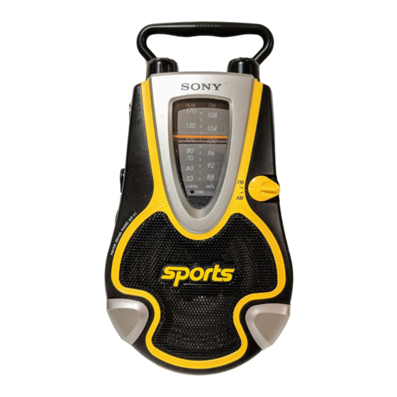
SPECIFICATIONS
Frequency range:
FM : 87.5 - 108 MHz
AM : 526.5 - 1 606.5 kHz
Speaker
Approx. 10.0 cm (4 inches) dia., 8 Ω
Output
v (earphone) jack (ø 3.5 mm minijack)
Power output
250 mW (at 10 % harmonic distortion)
Power requirements
4.5V DC, three R14 (size C) batteries
DC IN 4.5V jack accepts: Sony AC-E45HG AC
power adaptor (not supplied)
Dimensions
Approx. 130 × 237 × 71.5 mm (w/h/d)
× 9
× 2
1
3
7
(5
/
/
/
inches) incl. projecting parts
8
8
8
and controls
Mass
Approx. 673.5 g (1 lb 8 oz) incl. batteries
Design and specifications are subject to change without notice.
ICF-F1
AEP Model
FM/AM RADIO
Advertisement
Table of Contents

Related Manuals for Sony ICF-F1


Summary of Contents for Sony ICF-F1
- Page 1 Power output 250 mW (at 10 % harmonic distortion) Power requirements 4.5V DC, three R14 (size C) batteries DC IN 4.5V jack accepts: Sony AC-E45HG AC power adaptor (not supplied) Dimensions Approx. 130 × 237 × 71.5 mm (w/h/d) × 9 ×...
-
Page 2: Section 1 General
SECTION 1 This section is extracted from instruction manual. GENERAL Notes on chip component replacement • Never reuse a disconnected chip component. • Notice that the minus side of a tantalum capacitor may be damaged by heat. Flexible Circuit Board Repairing •... -
Page 3: Section 2 Disassembly
SECTION 2 DISASSEMBLY Note : Disassemble the unit in the order as shown below. Cabinet (rear) assy Chassis assy Speaker (SP1) Vol board Main board Note : Follow the disassembly procedure in the numerical order given. 2-1. CABINET (REAR) ASSY 4 Four screws (+BTP 3 ×... -
Page 4: Vol Board
2-4. VOL BOARD 6 Rack 2 Remove solderings 3 Vol board 5 Scale, dial 7 Screw (+P2.6 × 8) Two claws 4 Pointer 8 Gear (A), tuning capacitor 2-5. MAIN BOARD ASSY 8 LED board 6 Screw (+P 2.6 × 8) 7 Remove solderings 3 Three screws (+BTP 3 ×... -
Page 5: Section 3 Electrical Adjustments
SECTION 3 ELECTRICAL ADJUSTMENTS 2-6. DIAL POINTER • Repeat the procedures in each adjustment several times for the AM SECTION maximum level meter indication. • The frequency coverage and tracking adjustments should be finally BAND : AM done by the trimmer capacitors. Signal generator 1 Install the tuning capacitor gear (A) in the direction as shown while it is aligned with CV1. -
Page 6: Main Board
ICF-F1 SECTION 4 DIAGRAMS 4-1. PRINTED WIRING BOARDS MAIN BOARD BATTERY SIZE ''C'' LED BOARD (ICE DESIGNATION R14) 2PCS, 4.5V D3 (LIGHT) (11) 1-678-315 ANT1 FM TELESCOPIC ANTENNA JACK BOARD (SPEAKER) DC IN 4.5V BPF1 (BAND) CT1-2 CT1-3 TUNING 1-678-314... - Page 7 ICF-F1 4-2. SCHEMATIC DIAGRAM Note on Schematic Diagram: • All capacitors are in µF unless otherwise noted. pF: µµF 50 WV or less are not indicated except for electrolytics and tantalums. • All resistors are in Ω and W or less unless otherwise specified.
-
Page 8: Section 5 Exploded Views
SECTION 5 SECTION 6 JACK MAIN EXPLODED VIEWS ELECTRICAL PARTS LIST NOTE: NOTE: • -XX, -X mean standardized parts, so they may • The mechanical parts with no reference number • Due to standardization, replacements in the • CAPACITORS: • SEMICONDUCTORS have some differences from the original one. -
Page 9: Metal Chip
MAIN Ref. No. Part No. Description Remarks Ref. No. Part No. Description Remarks 1-216-853-11 METAL CHIP 470K 1/16W MISCELLANEOUS 1-216-833-11 RES-CHIP 1/16W ************** 1-216-801-11 METAL CHIP 1/16W 1-216-821-11 METAL CHIP 1/16W 1-501-222-81 ANTENNA, TELESCOPIC (FM) 1-216-821-11 METAL CHIP 1/16W 1-529-754-11 SPEAKER (10CM) ************************************************************** <... - Page 10 ICF-F1 Sony Corporation 2000E1636-1 Audio Entertainment Group 9-927-925-31 Printed in Japan © 2000.5 — 14 — Published by PE General Engineering Dept.
Need help?
Do you have a question about the ICF-F1 and is the answer not in the manual?
Questions and answers