Advertisement
Quick Links
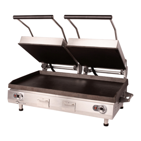
Sandwich Grill
Owner's Manual
Models
PGC28I, PSC28I
This manual includes material related to installation,
use , cleaning, and care. Exploded view[s], as well
as any available parts list[s] pertaining to the unit
covered by this manual are also included.
This manual must be read and understood by all
persons using or installing this appliance. Contact
your Star dealer if you have any questions concerning
installation, use, or maintenance of this equipment.
DO NOT DISCARD THIS MANUAL.
PSC28I
2M-Z22033
Rev. A
03.2017
•
•
Advertisement


Need help?
Do you have a question about the PGC28I and is the answer not in the manual?
Questions and answers