Advertisement
Quick Links
DS1/DSS – Instructions for
Installation and Use
If you have a DS2 please refer to
separate instructions on page 10.
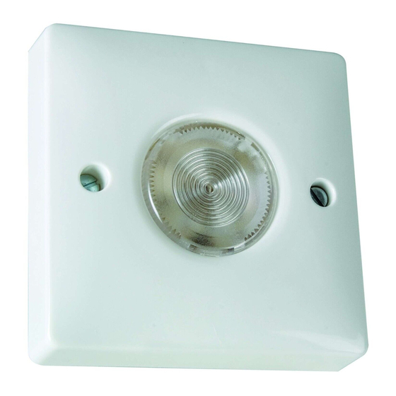
Tough flame-
retardant
polycarbonate
plate fits a
standard
single gang
1
wall box
16mm deep.
Fig 1 - Front of DS1 and DSS
1. General.
The DS1 is a time delay switch with an illuminated push button, which
replaces a standard single gang plate switch on a box 16mm deep. The
illumination guides the user to the push button and once this is pressed
the lights under control are switched on for a period from approximately
10 seconds to approximately 10 minutes adjustable by internal
potentiometer.
For situations requiring two-way and intermediate switching DSS's can be
used in conjunction with a single DS1. Section 5 shows how these can be
used in retrofit without wiring modifications and section 2b shows how
they should be wired in new installations.
Delay time
adjuster –
centre scale
Illuminated
gives
push button.
approximately
5 mins (linear
scale).
Fig 2a – Rear of DS1
Optional
push-in
2
screw covers
supplied.
SLAVE
Fig 2b – Rear of DSS
2a. Installation (Replacement of Single
ON/OFF Switches Only).
SL
L
FOR INSTALLATION OF DS1 & DSS's IN 2 WAY AND
INTERMEDIATE SWITCHING CONFIGURATIONS – SEE SECTION 5.
IF IN DOUBT CONSULT AN ELECTRICIAN. SWITCH OFF MAINS
ELECTRICITY.
Set the delay time adjuster on the DS1 to minimum (fully anticlockwise –
see fig 2a) to enable initial testing during commissioning.
Remove the existing light switch and transfer the two wires to the DS1
connecting them to terminals L and SL in either position. If two wires
were connected to either terminal on the original switch they must be kept
together and connected to either L or SL on the DS1.
Do not disturb any earthing wire connected to the wallbox terminal.
Ensure both terminals are tight before screwing the two plate fixing
3
screws supplied home sufficiently to locate the DS1 securely to the wall
box. Turn ON the mains supply.
2b. New Installation of a DS1 and Up to
25 DSS's..
In a new installation the DS1 and DSS's can be wired to give control of a
single lamp load by any of the switches.
This is shown in fig 3.
L
N
L, N - Mains Supply
L
L
IN
IN
L
L
MASTER
MASTER
DSS
DSS
Lamp Load
Fig 3
L
SL
DS1
Advertisement

Subscribe to Our Youtube Channel
Related Manuals for Timeguard DS1


Summary of Contents for Timeguard DS1
- Page 1 25 DSS’s.. 1. General. In a new installation the DS1 and DSS’s can be wired to give control of a single lamp load by any of the switches. The DS1 is a time delay switch with an illuminated push button, which This is shown in fig 3.
-
Page 2: Operation
(see fig 2a). The delay time can then be set to the required level and the DS1 fixed to the wall using the two fixing Fig 6 - Replacement Delay Switches fitted to circuit shown in fig. 4 screws. - Page 3 Further DSS’s can be added to replace any further intermediate switches in the system. SL - Switched Live MASTER Lamp If there are no intermediate switches (2 way switching) the before and Load after connections for both systems are shown in figs 8 to 11. Note that an in-line connector is required for the Strapping Cable System to provide continuity for the SL connection.
- Page 4 73/23/EEC & 89/336/EEC Installation and Use Permissible Loads: Filament lamps – 1.5kW Fluorescent – 18 – 500W If you have a DS1 working alone or Low voltage – 20 – 200W with one or more DSS’s please refer Resistive 2kW HELPLINE to separate instructions on page 1.
-
Page 5: Specifications
Time range Make sure that the wallbox is earthed if it is metal. Ensure that all three terminals 4. Operation. selector are tight before screwing the two plate fixing screws supplied home sufficiently to Whenever light or appliance operation is required press the push button locate the DS2 securely to the wall box. -
Page 6: Year Guarantee
3 years of the date of purchase, please return it to your supplier with proof of purchase and it will be replaced Cat No. DS1 free of charge. Should you encounter any difficulty 2 WIRE SLAVE SWITCH please contact our helpline on 020 8450 0515.
Need help?
Do you have a question about the DS1 and is the answer not in the manual?
Questions and answers