Table of Contents
Advertisement
Quick Links
Advertisement
Table of Contents

Subscribe to Our Youtube Channel
Related Manuals for HBS CPW 0604


Summary of Contents for HBS CPW 0604
- Page 1 CPW 0604 CNC Production Welder Operating Manual...
- Page 2 Phone +49 8131 511-0 +49 8131 511-100 E-mail post@hbs-info.com www.hbs-info.com CPW 0604 Operating Manual Issue 09/2013 Order No. BA CPW 0604 Translation of the Operating Manual Copyright: The information contained herein may not be copied, reproduced, adapted, merged, translated or used without the prior written consent of the copyright owner.
- Page 3 For your own sake you should know the safety instructions for operating your HBS stud welding units inside out.
- Page 4 If you should detect errors or mistakes right in this manual, please contact us: HBS Bolzenschweiss-Systeme GmbH & Co. KG Felix-Wankel-Strasse 18 85221 Dachau / Germany A feedback blank is provided in the appendix. CPW 0604 BA CPW 0604 Issue 10.09.13 (From Software-Release 0.0.1.31)
-
Page 5: Table Of Contents
Menu AUTOMATIC ..................34 4.4.1 Description of Operating Elements ................. 35 4.4.2 Automatic Options ....................42 Menu MANUAL / CONTACT ................ 43 4.5.1 Setting of the Contact Position ................45 CPW 0604 BA CPW 0604 Issue 10.09.13 (From Software-Release 0.0.1.31) - Page 6 4.23 Special Functions ..................143 Stud Welding Procedure ............. 144 Safety Instructions ..................144 Functional Principle of Stud Welding ............146 FTP Server ................... 147 Structure of the Drive................147 CPW 0604 BA CPW 0604 Issue 10.09.13 (From Software-Release 0.0.1.31)
- Page 7 Further Instructions - Tip Ignition ..........168 Guarantee Clauses ..............169 EC Declaration of Conformity ............. 170 Confirmation ................171 Feedback ..................172 Service & Support ............... 173 Index ..................... 174 CPW 0604 BA CPW 0604 Issue 10.09.13 (From Software-Release 0.0.1.31)
- Page 8 Table of Contents Table of Contents Table of Contents Table of Contents Table of Contents viii CPW 0604 BA CPW 0604 Issue 10.09.13 (From Software-Release 0.0.1.31)
-
Page 9: Important Data
________________ Stud length 2: ________________ Order No: __________________ Serial No: ________________ Stud length 3: ________________ Order No: __________________ Serial No: ________________ Power Unit: __________________________ Order No: __________________________ Serial No: __________________________ CPW 0604 BA CPW 0604 Issue 10.09.13 (From Software-Release 0.0.1.31) - Page 10 1 General CPW 0604 BA CPW 0604 Issue 10.09.13 (From Software-Release 0.0.1.31)
-
Page 11: General
Owners and operators make sure that the CNC Production Welder is only used as directed. During any activity such as transportation, set-up, (re-)assembly, production, maintenance etc. observe the information given in this operating manual. CPW 0604 BA CPW 0604 Issue 10.09.13 (From Software-Release 0.0.1.31) -
Page 12: Guide To This Operating Manual
All instructions contained in this manual must also be observed by qualified operators. The welding process and the sequence of procedures to carry out a weld are described in chapter 5. CPW 0604 BA CPW 0604 Issue 10.09.13 (From Software-Release 0.0.1.31) -
Page 13: Safety Symbols
Warning of hand injury Warning of danger of crushing Wear protective clothes Wear protective goggles Wear ear protection Observe operating manual Additional tips for operation and service safety Prompt – List CPW 0604 BA CPW 0604 Issue 10.09.13 (From Software-Release 0.0.1.31) -
Page 14: General Safety Instructions
(place of operation see section 11.1). Observing the operating manual of the used components is also part of the ”use as directed”. CPW 0604 BA CPW 0604 Issue 10.09.13 (From Software-Release 0.0.1.31) -
Page 15: Transportation, Packaging, Storage
In addition to this operating manual, you must observe the operating manual of the components like welding head, power unit(s), stud feeding units etc., as well as applicable accident prevention and safety instructions. CPW 0604 BA CPW 0604 Issue 10.09.13 (From Software-Release 0.0.1.31) -
Page 16: Markings
Safety symbols Replace illegible or damaged markings Before opening machine disconnect mains Observe operating manual Warning of dangerous electrical voltage Secure the following safety symbols in the area of welding place: CPW 0604 BA CPW 0604 Issue 10.09.13 (From Software-Release 0.0.1.31) - Page 17 1 General 1.7 Markings Markings CPW 0604 BA CPW 0604 Issue 10.09.13 (From Software-Release 0.0.1.31)
-
Page 18: Delivery
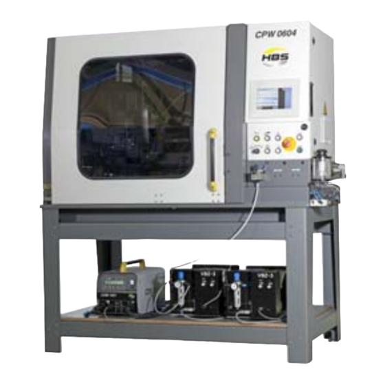
Welding machine CPW 0604 Project-depending Project directory CPW 0604 BA CPW 0604 (Operating manual and documentation) Note: Your machine may differ from the picture, depending on the equipment compo- nents. CPW 0604 BA CPW 0604 Issue 10.09.13 (From Software-Release 0.0.1.31) -
Page 19: Starting-Up
Ensure that air is able to circulate freely through the housing. If heat is built-up inside the housing caused by bad air circulati- on, the stud welding unit will be seriously damaged. CPW 0604 BA CPW 0604 Issue 10.09.13 (From Software-Release 0.0.1.31) -
Page 20: Requirements Of Operating Personnel
Any electrically conductive and electro-magnetically sensitive parts must be removed from your body before the work starts to avoid any danger or possible damages caused by electrical voltage or electromagnetic fields. CPW 0604 BA CPW 0604 Issue 10.09.13 (From Software-Release 0.0.1.31) -
Page 21: Requirements And Installation Instruction With Hbs Base Frame
3 Starting-up 3.3 Requirements and Installation Instruction with HBS Base Frame Requirements and Installation Instruction with HBS Base Frame CPW 0604 BA CPW 0604 Issue 10.09.13 (From Software-Release 0.0.1.31) -
Page 22: Connecting The Welding Machine To The Primary Power Supply
Have an electrician check whether the outlet to which you want to connect the stud welding machine is correctly grounded. Switch off the stud welding machine. Insert the primary plug (CEE plug) into the checked outlet. Front view of the stud welding machine CPW 0604 BA CPW 0604 Issue 10.09.13 (From Software-Release 0.0.1.31) -
Page 23: Connecting The Power Units To The Cnc Production Welder
Check the plug connections regularly before the start of work to ensure that they are properly locked. In case of loose con- nection, heat may build up in the plug and may destroy the entire plug connection. CPW 0604 BA CPW 0604 Issue 10.09.13 (From Software-Release 0.0.1.31) - Page 24 Before welding, lay out the cables lengthwise. Fix the cables. Strong magnetic fields occur during welding which may cause a movement of the cables. This may cause a slackness of the connections. Connections VBZ / PBZ CPW 0604 BA CPW 0604 Issue 10.09.13 (From Software-Release 0.0.1.31)
- Page 25 Such power units (IT / ARC) must be re-equipped with the module undervoltage release, order no. 8080590! 3-phase power units must be connected by the customer and separately be fused! CPW 0604 BA CPW 0604 Issue 10.09.13 (From Software-Release 0.0.1.31)
- Page 26 3 Starting-up 3.5 Connecting the Power Units to the CNC Production Welder Other connections CPW 0604 BA CPW 0604 Issue 10.09.13 (From Software-Release 0.0.1.31)
-
Page 27: Connect Pneumatic Stud Switch(Es) (Pbw) To The Stud Welding Machine
3.6 Connect Pneumatic Stud Switch(es) (PBW) to the Stud Welding Machine Connect Pneumatic Stud Switch(es) (PBW) to the Stud Welding Machine PBW: distribution and connections for 2 stud lengths: PBW: distribution and connections for 3 stud lengths: CPW 0604 BA CPW 0604 Issue 10.09.13 (From Software-Release 0.0.1.31) -
Page 28: Pneumatic Diagram
3 Starting-up 3.7 Pneumatic Diagram Pneumatic Diagram CPW 0604 BA CPW 0604 Issue 10.09.13 (From Software-Release 0.0.1.31) -
Page 29: Change Working Place
CNC Production Welder. Proceed in reversed sequence as described in sections 3.5 and 3.6. After changing the workplace, check the components and the ground cables for possible damage or missing components. CPW 0604 BA CPW 0604 Issue 10.09.13 (From Software-Release 0.0.1.31) -
Page 30: Function
Operating Elements 4.1.1 Touch-Panel with Control Using the menu on the touch-panel, the operator can carry out the functions which are described from chapter 4.2 onwards. 4.1.2 Operating Elements, Overview CPW 0604 BA CPW 0604 Issue 10.09.13 (From Software-Release 0.0.1.31) - Page 31 To avoid misoperation, both push buttons must be pressed within a certain time to start the action to be carried out! Note: The selected function is only carried out as long as both push buttons are pressed! CPW 0604 BA CPW 0604 Issue 10.09.13 (From Software-Release 0.0.1.31)
-
Page 32: Menu Initialize
This is a manual function! A collision with possible obstructions must be avoided by the operator! Push button ON must be engaged. Selection touch keys for axes to be initialized. CPW 0604 BA CPW 0604 Issue 10.09.13 (From Software-Release 0.0.1.31) -
Page 33: Menu Startmenu
Starting from this menu, further menus can be selected, depending on the job: For AUTOMATIC set key switch to position „Start“ or „Start with door“. For MANUAL / CONTACT set key switch to position „Hand“. CPW 0604 BA CPW 0604 Issue 10.09.13 (From Software-Release 0.0.1.31) -
Page 34: Menu Automatic
10%) – Program runtime in [ms] : Runtime between Start and M30 command in the program code. – Status indication line. – Actual positions of X, Y and Z axes. CPW 0604 BA CPW 0604 Issue 10.09.13 (From Software-Release 0.0.1.31) -
Page 35: Description Of Operating Elements
Start after error in automatic run Touch key „LINE >>“ and push button „START“ starts automatic run in the next program line! Stud must be removed from the chuck in advance! CPW 0604 BA CPW 0604 Issue 10.09.13 (From Software-Release 0.0.1.31) - Page 36 - Beam indicator displays the currently set speed value of Automatic Speed. - Touch key „MIN %“ decreases speed. Minimum value which can be set: 10% of maximum Automatic Speed. CPW 0604 BA CPW 0604 Issue 10.09.13 (From Software-Release 0.0.1.31)
- Page 37 Using „Pos XY“ releases and carries out subsequent positioning commands. During execution, the door is locked. Only after termination of movement, the door lock is released again. Destinations are only X and Y coordinates! Z coordinates remain unregarded! CPW 0604 BA CPW 0604 Issue 10.09.13 (From Software-Release 0.0.1.31)
- Page 38 Display after executing with the “AUTO“ or „LINE>“ touch key until end of the program. Touch key CLS With „CLS“, the already set and displayed stud image is deleted and the program is reset to line start. CPW 0604 BA CPW 0604 Issue 10.09.13 (From Software-Release 0.0.1.31)
- Page 39 Marking of the stud position from stud feeder, length 2 Marking of the stud position from stud feeder, length 3 Marking of a pure movement position without welding Marking of a stud position for rewelding CPW 0604 BA CPW 0604 Issue 10.09.13 (From Software-Release 0.0.1.31)
- Page 40 Start rewelding: close door and start with the „START“ pushbutton If no stud positions are selected for rewelding, the program is executed without Z-movement. To quit rewelding mode: „STOP“ pushbutton and touch key „CANCEL“. CPW 0604 BA CPW 0604 Issue 10.09.13 (From Software-Release 0.0.1.31)
- Page 41 4 Function 4.4 Menu AUTOMATIC Example: Display after selecting two stud positions for rewelding: Example: Display after selecting two stud positions for rewelding and subsequent selection with „SEL>>>“ for program continuation CPW 0604 BA CPW 0604 Issue 10.09.13 (From Software-Release 0.0.1.31)
-
Page 42: Automatic Options
Shift counter (work pieces) can be set to zero. Display CP signal Only with set option [Parameter CP signal = 1]. Only in connection with power units with CP signal output! CPW 0604 BA CPW 0604 Issue 10.09.13 (From Software-Release 0.0.1.31) -
Page 43: Menu Manual / Contact
– Display of the shortest stud length of the selected program. – Software potentiometer: Variable speed preselection for manual mode (100 % - 10 %). – Display of preseted speed in m/min. CPW 0604 BA CPW 0604 Issue 10.09.13 (From Software-Release 0.0.1.31) - Page 44 4 Function 4.5 Menu MANUAL / CONTACT Coordinate systems CPW 0604 BA CPW 0604 Issue 10.09.13 (From Software-Release 0.0.1.31)
-
Page 45: Setting Of The Contact Position
U3 = welding head 3 / Z axis U3 U4 = welding head 4 / Z axis U4 Selection of option Bx: B0 = without option B1 = downholder B2 = spray B3 = downholder and spray CPW 0604 BA CPW 0604 Issue 10.09.13 (From Software-Release 0.0.1.31) - Page 46 Input of stud length which is fed by selected option Vx! The entered stud length must match the real stud length, otherwise a wrong contact signal calibration or defective welding occur! CPW 0604 BA CPW 0604 Issue 10.09.13 (From Software-Release 0.0.1.31)
-
Page 47: Positioning Of Axes In Manual Mode
Execution of positioning via push buttons confirmation and START! Selection of drive direction and axis: The green light displays the currently active condition. Execution of positioning via push buttons confirmation and START! CPW 0604 BA CPW 0604 Issue 10.09.13 (From Software-Release 0.0.1.31) - Page 48 Selection by touch key „XY POS“. This touch key is active if the green light is displayed. The green light displays the currently active condition. Execution of positioning via push buttons confirmation and START! CPW 0604 BA CPW 0604 Issue 10.09.13 (From Software-Release 0.0.1.31)
-
Page 49: Calibration Of Contact Signal
This touch key is active if the green light is displayed. The green light display shows the currently active condition. Execution of stud feeding via push buttons confirmation and START! CPW 0604 BA CPW 0604 Issue 10.09.13 (From Software-Release 0.0.1.31) -
Page 50: Calibration Of Contact Position Z
Using the touch key „ENTER“ the current Z position is accepted and saved as new contact position Z. Figure: Contact position After calibration, move the Z axis away from work piece in home position! CPW 0604 BA CPW 0604 Issue 10.09.13 (From Software-Release 0.0.1.31) -
Page 51: Check And Determination Of Welding Parameters
U3 = welding head 3 / Z axis U3 U4 = welding head 4 / Z axis U4 Selection of option Bx: B0 = without option B1 = downholder B2 = spray B3 = downholder and spray CPW 0604 BA CPW 0604 Issue 10.09.13 (From Software-Release 0.0.1.31) - Page 52 This touch key is active if the green light is displayed. The green light display shows the currently active condition. Execution to feed a stud via push buttons confirmation and START! CPW 0604 BA CPW 0604 Issue 10.09.13 (From Software-Release 0.0.1.31)
- Page 53 The welding head is moved with push buttons from home position to welding position. The following is taken into consideration: – Set option Bx (see above) – Set option Vx (see above) – Stud length – Penetration depth of actively selected program CPW 0604 BA CPW 0604 Issue 10.09.13 (From Software-Release 0.0.1.31)
- Page 54 Selection via touch key „WELD“. This touch key is active if the green light is displayed. The green light display shows the currently active condition. Execution of positioning via push buttons confirmation and START! CPW 0604 BA CPW 0604 Issue 10.09.13 (From Software-Release 0.0.1.31)
- Page 55 Selection via touch key „HEAD up“ This touch key is active if the green light is displayed. The green light display shows the currently active condition. Execution of positioning via push buttons confirmation and START! CPW 0604 BA CPW 0604 Issue 10.09.13 (From Software-Release 0.0.1.31)
-
Page 56: Further Functions
Minimum value which can be set: 10% of maximum manual speed. Quit the menu All functions are set to initial state! Z axes must be removed to home position (up)! CPW 0604 BA CPW 0604 Issue 10.09.13 (From Software-Release 0.0.1.31) - Page 57 Selection via touch key „Stopper“. This touch key is active if the green light is displayed. The green light display shows the currently active condition. Execution of positioning via push buttons confirmation and START! CPW 0604 BA CPW 0604 Issue 10.09.13 (From Software-Release 0.0.1.31)
-
Page 58: Menu Equipment
The change of colour shows whether the selected function is active or not: yellow = inactive green = active In the case touch keys are marked with a yellow circle and a black square, the function can only be executed in combination! CPW 0604 BA CPW 0604 Issue 10.09.13 (From Software-Release 0.0.1.31) - Page 59 The pneumatic stud switch 2 is moved in working position with a press on the keys. Another press resets the function. T ouc h ke y and func tion will only be ac tiv e if the re late d option is re leas ed in the parameter s e tting . CPW 0604 BA CPW 0604 Issue 10.09.13 (From Software-Release 0.0.1.31)
-
Page 60: Menu Setup Cnc
4.7 Menu SETUP CNC Menu SETUP CNC In this menu the offsets between axis-zero position and work piece-zero position are defined. Changes without check may negatively affect the machine accuracy! CPW 0604 BA CPW 0604 Issue 10.09.13 (From Software-Release 0.0.1.31) - Page 61 A change of offset parameters is only possible after a password input! Password level: From level 1: Level 1 is for tool setters Touch key EXIT The menu „Setup CNC“ is quit. CPW 0604 BA CPW 0604 Issue 10.09.13 (From Software-Release 0.0.1.31)
-
Page 62: Menus Program Edit / Program Select
Touch key „PROGRAM SELECT“: – Selection of a program – Edit a program name – Copy programs – New program creation – Deletion of a program CPW 0604 BA CPW 0604 Issue 10.09.13 (From Software-Release 0.0.1.31) -
Page 63: Menu Program Select
All programs are saved and managed on a storage medium with USB connection. Program names can be entered via an alphanumeric touch key board (Touch). The program name must consist of at least 4 digits and maximum 23 digits! CPW 0604 BA CPW 0604 Issue 10.09.13 (From Software-Release 0.0.1.31) - Page 64 <<100>> : Scrolling in step width 100 Green light displays the selected condition. Touch key Pg Up Upwards scrolling through the program administration. Touch key Pg Dn Downwards scrolling through the program administration. CPW 0604 BA CPW 0604 Issue 10.09.13 (From Software-Release 0.0.1.31)
- Page 65 Using the touch key „NEW“ the input mode „New Program“ is activated. Touch key „New Program“ Using the touch key „New program“ the touch-keyboard is activated to enter the new program name: (figure similar) CPW 0604 BA CPW 0604 Issue 10.09.13 (From Software-Release 0.0.1.31)
- Page 66 This program does not contain any content and can subse- quently be processed in the program editor! The new program is automatically set to „active“ and filed. CPW 0604 BA CPW 0604 Issue 10.09.13 (From Software-Release 0.0.1.31)
- Page 67 Using the touch key „COPY“ the input mode „Copy Program“ is activated. Touch key „Copy of“ Using the touch key „Copy of“ the touch-keyboard is activated to enter the new program name: (figure similar) CPW 0604 BA CPW 0604 Issue 10.09.13 (From Software-Release 0.0.1.31)
- Page 68 In the case that the program name already exists, a warning is displayed: Program already exists! Otherwise the new program is automatically set to „active“ and filed: CPW 0604 BA CPW 0604 Issue 10.09.13 (From Software-Release 0.0.1.31)
-
Page 69: Edit A Program
Using the touch key „EDIT“ the program name of a program can be changed. Touch key „Edit of“ Using the touch key „Edit of“ the touch-keyboard is activated to enter the new program name: (figure similar) CPW 0604 BA CPW 0604 Issue 10.09.13 (From Software-Release 0.0.1.31) - Page 70 In the case that the program name already exists, a warning is displayed: Program already exists! Otherwise the changed program is automatically set to „active“ and filed. CPW 0604 BA CPW 0604 Issue 10.09.13 (From Software-Release 0.0.1.31)
- Page 71 The program is not deleted! Touch key ENTER Using the touch key „ENTER“ the selected program is deleted. If the program was mistakenly deleted, note the description of the UNDO function for deleted programs! CPW 0604 BA CPW 0604 Issue 10.09.13 (From Software-Release 0.0.1.31)
- Page 72 Example: You search for „prg“: All found programs that begin with „prg“ are highlighted in green. Now select a program with which you wish to work further. CPW 0604 BA CPW 0604 Issue 10.09.13 (From Software-Release 0.0.1.31)
- Page 73 Touch key „Clear Wastebasket“ Using the touch key „Clear Wastebasket“ the index list of the deleted programs is reset to 0. This touch key is only displayed after 10 deletion processes! CPW 0604 BA CPW 0604 Issue 10.09.13 (From Software-Release 0.0.1.31)
- Page 74 To restore the programs, they must be shifted from the directory \Wastebasket to the directory \Program! After this action, the system must be restarted to update the directory of existing programs. CPW 0604 BA CPW 0604 Issue 10.09.13 (From Software-Release 0.0.1.31)
-
Page 75: Description Of The Functions In Program Editor
The first menu is used to enter so-called Header dates. The second menu is used to enter the program sequence. Menu to enter data assigned to the program header Menu to enter the program sequence CPW 0604 BA CPW 0604 Issue 10.09.13 (From Software-Release 0.0.1.31) - Page 76 Shielding gas = 1 : shielding gas pre-flow time Delay post-weld: Shielding gas = 0 : settling time after welding! Shielding gas = 1 : shielding gas post flow time CPW 0604 BA CPW 0604 Issue 10.09.13 (From Software-Release 0.0.1.31)
- Page 77 Used for programs that produce multiple workpieces in a single program run. The shift counter is always increased by the entered number. Yellow marked input boxes: These parameters are internally processed, thus the input is checked for required parameter limits! CPW 0604 BA CPW 0604 Issue 10.09.13 (From Software-Release 0.0.1.31)
- Page 78 Enter parameters which are between upper and lower limits. Yellow marked input boxes with red border: For this command, the inputs are outside the permissible limits or required data are missing! CPW 0604 BA CPW 0604 Issue 10.09.13 (From Software-Release 0.0.1.31)
- Page 79 4 Function 4.8 Menus PROGRAM EDIT / PROGRAM SELECT Blue marked input boxes: These parameters are not (yet) internally processed but used for documentation of set values. CPW 0604 BA CPW 0604 Issue 10.09.13 (From Software-Release 0.0.1.31)
- Page 80 If you quit the editor in spite of faulty inputs, the program will be stored in that condition! The program is marked as defective (see figure below) and cannot be started in automatic mode! CPW 0604 BA CPW 0604 Issue 10.09.13 (From Software-Release 0.0.1.31)
- Page 81 For parameter „counter shift control“ = 1 visible and active. At the end of each program, the shift counter is increased by the stored value. Value > 1 for multiple workpiece holders. CPW 0604 BA CPW 0604 Issue 10.09.13 (From Software-Release 0.0.1.31)
- Page 82 4.8 Menus PROGRAM EDIT / PROGRAM SELECT Touch key EXIT Quit the menu PROGRAM EDITOR Command input in program editor: The editor touch keys are displayed which are required for each command of line parameter input. CPW 0604 BA CPW 0604 Issue 10.09.13 (From Software-Release 0.0.1.31)
- Page 83 In the case that required data (yellow input boxes) are insuffi- cient or out of internal limits, a scrolling is not possible! Touch key EXIT Touch key to quit the menu PROGRAM EDITOR CPW 0604 BA CPW 0604 Issue 10.09.13 (From Software-Release 0.0.1.31)
- Page 84 Command Input Options and Stud Length Display of the related options is depending on machine configu- ration. Touch key EXIT Touch key to quit the menu INPUT OPTIONS and INPUT STUDS CPW 0604 BA CPW 0604 Issue 10.09.13 (From Software-Release 0.0.1.31)
- Page 85 Stopper in active position (when parameter „Special function = 1“) Stopper in released position (when parameter „Special function = 1“) Plunger in released position Plunger in active position End of program CPW 0604 BA CPW 0604 Issue 10.09.13 (From Software-Release 0.0.1.31)
- Page 86 4 Function 4.8 Menus PROGRAM EDIT / PROGRAM SELECT Command overview G79 Command overview G78 CPW 0604 BA CPW 0604 Issue 10.09.13 (From Software-Release 0.0.1.31)
- Page 87 4 Function 4.8 Menus PROGRAM EDIT / PROGRAM SELECT Command overview G00 Command overview G01 CPW 0604 BA CPW 0604 Issue 10.09.13 (From Software-Release 0.0.1.31)
- Page 88 4 Function 4.8 Menus PROGRAM EDIT / PROGRAM SELECT Command overview G41 Command overview G20 CPW 0604 BA CPW 0604 Issue 10.09.13 (From Software-Release 0.0.1.31)
- Page 89 4 Function 4.8 Menus PROGRAM EDIT / PROGRAM SELECT Command overview G22 Command overview G54 CPW 0604 BA CPW 0604 Issue 10.09.13 (From Software-Release 0.0.1.31)
- Page 90 4 Function 4.8 Menus PROGRAM EDIT / PROGRAM SELECT Command overview G53 Command overview G90 CPW 0604 BA CPW 0604 Issue 10.09.13 (From Software-Release 0.0.1.31)
- Page 91 4 Function 4.8 Menus PROGRAM EDIT / PROGRAM SELECT Command overview G91 Command overview M98 CPW 0604 BA CPW 0604 Issue 10.09.13 (From Software-Release 0.0.1.31)
- Page 92 4 Function 4.8 Menus PROGRAM EDIT / PROGRAM SELECT Command overview M99 Command overview M00 CPW 0604 BA CPW 0604 Issue 10.09.13 (From Software-Release 0.0.1.31)
- Page 93 4 Function 4.8 Menus PROGRAM EDIT / PROGRAM SELECT Command overview M10 Command overview M11 CPW 0604 BA CPW 0604 Issue 10.09.13 (From Software-Release 0.0.1.31)
- Page 94 4 Function 4.8 Menus PROGRAM EDIT / PROGRAM SELECT Command overview M20 Command overview M21 CPW 0604 BA CPW 0604 Issue 10.09.13 (From Software-Release 0.0.1.31)
- Page 95 4 Function 4.8 Menus PROGRAM EDIT / PROGRAM SELECT Command overview M22 Command overview M23 CPW 0604 BA CPW 0604 Issue 10.09.13 (From Software-Release 0.0.1.31)
- Page 96 4 Function 4.8 Menus PROGRAM EDIT / PROGRAM SELECT Command overview M30 CPW 0604 BA CPW 0604 Issue 10.09.13 (From Software-Release 0.0.1.31)
- Page 97 4 Function 4.8 Menus PROGRAM EDIT / PROGRAM SELECT Programming example: Without programmable Z axis CPW 0604 BA CPW 0604 Issue 10.09.13 (From Software-Release 0.0.1.31)
- Page 98 4 Function 4.8 Menus PROGRAM EDIT / PROGRAM SELECT Programming example: With programmable Z axis CPW 0604 BA CPW 0604 Issue 10.09.13 (From Software-Release 0.0.1.31)
- Page 99 4 Function 4.8 Menus PROGRAM EDIT / PROGRAM SELECT Programming example: With subprogram and programmable stop CPW 0604 BA CPW 0604 Issue 10.09.13 (From Software-Release 0.0.1.31)
- Page 100 4 Function 4.8 Menus PROGRAM EDIT / PROGRAM SELECT Programming example: With subprogram for Pick Up CPW 0604 BA CPW 0604 Issue 10.09.13 (From Software-Release 0.0.1.31)
-
Page 101: Menu Program Graph
Note : In dependence of machine configuration! Example: Display after executing with the “AUTO“ or „LINE>“ touch key until end of the program Up to 200 stud positions can be displayed. CPW 0604 BA CPW 0604 Issue 10.09.13 (From Software-Release 0.0.1.31) - Page 102 Marking of the stud position from stud feeder, length 1 Marking of the stud position from stud feeder, length 2 Marking of the stud position from stud feeder, length 3 Marking of a pure movement position without welding CPW 0604 BA CPW 0604 Issue 10.09.13 (From Software-Release 0.0.1.31)
-
Page 103: Menu Parameter Cnc
General axes and motor parameters Z axis Menu for inputs and outputs Menu for actual machine configuration Menu for set values welding parameters Menu for spare and wear parts HBS CPW 0604 BA CPW 0604 Issue 10.09.13 (From Software-Release 0.0.1.31) - Page 104 4 Function 4.10 Menu PARAMETER CNC General These menus are password protected! Access for editing is depending on different password levels! Only yellow marked boxes can be edited! CPW 0604 BA CPW 0604 Issue 10.09.13 (From Software-Release 0.0.1.31)
-
Page 105: Description Of Parameters
2 2 = With RS232 interface: electronic length compensation is active! 0 = None 1 = Downholder Options Bx from 2 2 = Spray 3 = Downholder with spray CPW 0604 BA CPW 0604 Issue 10.09.13 (From Software-Release 0.0.1.31) - Page 106 4 Function 4.10 Menu PARAMETER CNC CPW 0604 BA CPW 0604 Issue 10.09.13 (From Software-Release 0.0.1.31)
-
Page 107: Overview - Parameters X Axis
4 Function 4.10 Menu PARAMETER CNC 4.10.2 Overview - Parameters X Axis General axis parameters X axis Motor parameters X axis CPW 0604 BA CPW 0604 Issue 10.09.13 (From Software-Release 0.0.1.31) - Page 108 A complete restart of the machine is a must after changes to motor/axis parameters. This is necessary to sustainably store the motor parameters in the EEPROM of the axes drives. CPW 0604 BA CPW 0604 Issue 10.09.13 (From Software-Release 0.0.1.31)
-
Page 109: Overview - Parameters Y Axis
4 Function 4.10 Menu PARAMETER CNC 4.10.3 Overview - Parameters Y Axis General axis parameters Y axis Motor parameters Y axis CPW 0604 BA CPW 0604 Issue 10.09.13 (From Software-Release 0.0.1.31) - Page 110 A complete restart of the machine is a must after changes to motor/axis parameters. This is necessary to sustainably store the motor parameters in the EEPROM of the axes drives. CPW 0604 BA CPW 0604 Issue 10.09.13 (From Software-Release 0.0.1.31)
-
Page 111: Overview - Parameters Zu1 Axis
4 Function 4.10 Menu PARAMETER CNC 4.10.4 Overview - Parameters ZU1 Axis General axis parameters ZU1 axis Motor parameters ZU1 axis CPW 0604 BA CPW 0604 Issue 10.09.13 (From Software-Release 0.0.1.31) - Page 112 A complete restart of the machine is a must after changes to motor/axis parameters. This is necessary to sustainably store the motor parameters in the EEPROM of the axes drives. CPW 0604 BA CPW 0604 Issue 10.09.13 (From Software-Release 0.0.1.31)
-
Page 113: Menu I/O Test
Light display white: No input active Light display green: Input active Outputs at the CAN OPEN field bus spot Light display white: No output active Light display green: Output activated CPW 0604 BA CPW 0604 Issue 10.09.13 (From Software-Release 0.0.1.31) -
Page 114: Functions
Touch key for change-over to the next menu. Touch key <MENU Touch key for change-over to the previous menu. Touch key EXIT Quit the menu I/O TEST. Touch key ASSIST Call-up the assistance menu for I/O TEST CPW 0604 BA CPW 0604 Issue 10.09.13 (From Software-Release 0.0.1.31) -
Page 115: Menu Configuration
– Display of existing machine configuration – Information on software – Setting system time (PLC time) and system date (PLC date) Touch key EXIT Touch key to quit the menu CONFIGURATION CPW 0604 BA CPW 0604 Issue 10.09.13 (From Software-Release 0.0.1.31) -
Page 116: Setting The System Time
Using the touch key „Min“ the minutes can be edited via Touch-numPad. Touch key Sec Using the touch key „Sec“ the seconds can be edited via Touch-numPad. Touch key SET Using the touch key „SET“ the new time is accepted. CPW 0604 BA CPW 0604 Issue 10.09.13 (From Software-Release 0.0.1.31) -
Page 117: Setting The System Date
Using the touch key „MONTH“ the month can be edited via Touch-numPad. Touch key YEAR Using the touch key „YEAR“ the year can be edited via Touch-numPad. Touch key SET Using the touch key „SET“ the entered date is accepted. CPW 0604 BA CPW 0604 Issue 10.09.13 (From Software-Release 0.0.1.31) -
Page 118: Menu Standard Values
4.13 Menu STANDARD VALUES 4.13 Menu STANDARD VALUES Here you can find recommended standard values for setting a welding job. Note the instruction below! Touch key EXIT To quit the menu STANDARD VALUES. CPW 0604 BA CPW 0604 Issue 10.09.13 (From Software-Release 0.0.1.31) - Page 119 Overview standard value parameters If no parameter sets are stored, a note will be displayed: --- No data base available! --- The following parameters can be taken from the standard value tables: CPW 0604 BA CPW 0604 Issue 10.09.13 (From Software-Release 0.0.1.31)
-
Page 120: Menu Spare Parts
Touch key to switch to the next menu. Touch key EXIT Touch key to quit the menu SPARE PARTS. Touch key <MENU Touch key to switch to the previous menu. CPW 0604 BA CPW 0604 Issue 10.09.13 (From Software-Release 0.0.1.31) - Page 121 Touch key to switch to the next menu. Touch key <MENU Touch key to switch to the previous menu. Touch key EXIT Touch key to quit the menu SPARE PARTS. CPW 0604 BA CPW 0604 Issue 10.09.13 (From Software-Release 0.0.1.31)
- Page 122 Touch key to switch to the next menu. Touch key <MENU Touch key to switch to the previous menu. Touch key EXIT Touch key to quit the menu SPARE PARTS. CPW 0604 BA CPW 0604 Issue 10.09.13 (From Software-Release 0.0.1.31)
-
Page 123: Menu System
Menu for network settings Menu for machine settings Menu for packed malfunctions Menu for malfunction (ring buffer) archive Parameters for RS232 interface Menu for counter reading Menu for malfunction safety door CPW 0604 BA CPW 0604 Issue 10.09.13 (From Software-Release 0.0.1.31) -
Page 124: Menu Can Status
Participant status 3 = error CAN member Participant status 4 = Waiting for member with CAN-status 3 Participant status 5 = All members OK Touch key EXIT To quit the menu CAN STATUS CPW 0604 BA CPW 0604 Issue 10.09.13 (From Software-Release 0.0.1.31) - Page 125 4.16 Menu CAN STATUS Touch key ASSIST To call the assistance menu for CAN STATUS The functions of a menu are explained in short: Touch key EXIT To quit the menu CAN STATUS CPW 0604 BA CPW 0604 Issue 10.09.13 (From Software-Release 0.0.1.31)
-
Page 126: Menu System-Address
– Gateway. IP address: Setting for HBS service Machine address must be set to 192.168.100.190, release for service-laptop: Addresses 192.168.100.191 and 192.168.100.192 Touch key EXIT To quit the menu SYSTEM-ADDRESS CPW 0604 BA CPW 0604 Issue 10.09.13 (From Software-Release 0.0.1.31) - Page 127 – the machine must be restarted or – the control must be rebooted! Touch key SET Using the touch key „SET“ all changes are accepted. Touch key EXIT To quit the menu SYSTEM-ADDRESS. CPW 0604 BA CPW 0604 Issue 10.09.13 (From Software-Release 0.0.1.31)
-
Page 128: Menu System-Setting
FTP server or directly from the USB storage and archieve Touch key EDIT Touch key release is only possible after password input! Password level: from level 2: Level 2 is intended for HBS authorized personnel (service). CPW 0604 BA CPW 0604 Issue 10.09.13 (From Software-Release 0.0.1.31) - Page 129 4.18 Menu SYSTEM-SETTING Touch key UpLoad Restores the delivery condition or the last saved parameter set. Touch key DownLoad Saves the actual parameter set Touch key EXIT To quit the menu SYSTEM. CPW 0604 BA CPW 0604 Issue 10.09.13 (From Software-Release 0.0.1.31)
-
Page 130: Menu Alert Message
Push button INIT / RESET After elimination of the malfunction(s), you can confirm with the push button „INIT / RESET“ and alert messages are deleted. Touch key EXIT To quit the menu ALERT MESSAGE CPW 0604 BA CPW 0604 Issue 10.09.13 (From Software-Release 0.0.1.31) - Page 131 Axis could not carry out Initialize error_ZU3 initialization > operation? initialization Limit switch defective? Cancellation at the end of Axis could not carry out Initialize error_ZU4 initialization > operation? initialization Limit switch defective? CPW 0604 BA CPW 0604 Issue 10.09.13 (From Software-Release 0.0.1.31)
- Page 132 Check electrically limit switch, program entries? Check parameters (limits) , position limit switch? Axis is positionned on limit Limit switch minus active_ZU4 switch Check electrically limit switch, program entries? CPW 0604 BA CPW 0604 Issue 10.09.13 (From Software-Release 0.0.1.31)
- Page 133 Safety PLC does not release Power Removal Motor_ZU3 is active motor : Service Emergency power-off of axis Safety PLC does not release Power Removal Motor_ZU4 is active motor : Service CPW 0604 BA CPW 0604 Issue 10.09.13 (From Software-Release 0.0.1.31)
- Page 134 Error Control Process CP_ZU3 Set limits were reached Check function of connected power unit Check parameter adjustments Error Control Process CP_ZU4 Set limits were reached Check function of connected power unit CPW 0604 BA CPW 0604 Issue 10.09.13 (From Software-Release 0.0.1.31)
- Page 135 Check connections, PU switched on, PU type? PU does not provide a Power unit not ready_ZU3 ready signal before Charge voltage not yet OK?: welding Increase delay before welding! CPW 0604 BA CPW 0604 Issue 10.09.13 (From Software-Release 0.0.1.31)
- Page 136 Read error measuring module Defective data format Check connections, PU RS232_ZU3 received switched on, PU type? Read error measuring module Defective data format Check connections, PU RS232_ZU4 received switched on, PU type? CPW 0604 BA CPW 0604 Issue 10.09.13 (From Software-Release 0.0.1.31)
- Page 137 Check limit switch for Error limit switch stopper AS Cylinder does not reaches position or electrically end position signal for work Only when parameter position Check machine configuration Special function = 1 CPW 0604 BA CPW 0604 Issue 10.09.13 (From Software-Release 0.0.1.31)
- Page 138 Error Reset of delivery condition parameters could not be directory? read USB medium existing? ; File with delivery Check formatting Error Reset of delivery condition parameters could not be saved Check write protection CPW 0604 BA CPW 0604 Issue 10.09.13 (From Software-Release 0.0.1.31)
-
Page 139: Menu Rs232
The parameters of the RS232 interface of the control system are managed in this menu. Touch key EDIT Touch key release is only possible after password input! Password level: from level 2: Level 2 is intended for HBS authorized personnel (service). Only yellow marked boxes can be edited! -
Page 140: Menu Counter
This function is used to count – machined work pieces: Number of starts in automatic run – executed welds: Number of total welds. – operating hours. Touch key EXIT To quit the menu COUNTER CPW 0604 BA CPW 0604 Issue 10.09.13 (From Software-Release 0.0.1.31) -
Page 141: Menu Safety Door
If the machine is switched off in this error case, this menu must manually be selected for re-initialization! Touch key EXIT To quit the menu SAFETY DOOR. CPW 0604 BA CPW 0604 Issue 10.09.13 (From Software-Release 0.0.1.31) - Page 142 0 min (e.g. guard door misalignment) 10 flash pulses Solenoid temperature too high 0 min The solenoid is too hot: T > 70 °C Continuous red Internal failure 0 min CPW 0604 BA CPW 0604 Issue 10.09.13 (From Software-Release 0.0.1.31)
-
Page 143: Special Functions
Special function: 4 HBS Special function Workpiece sensor with detection of a workpiece change and link to „start with door“ (only with sensor box CPW 8821391 and premating door contact 8821748) CPW 0604 BA CPW 0604 Issue 10.09.13 (From Software-Release 0.0.1.31) -
Page 144: Stud Welding Procedure
In this way, you avoid the risk of damage by electric shock or influence of electromagnetic fields. CPW 0604 BA CPW 0604 Issue 10.09.13 (From Software-Release 0.0.1.31) - Page 145 Please note that in your country additional standards and safety conditions (especially rules for accident prevention) may differ from the standards mentioned in this operating manual. CPW 0604 BA CPW 0604 Issue 10.09.13 (From Software-Release 0.0.1.31)
-
Page 146: Functional Principle Of Stud Welding
In case of any accidents whatsoever, advise a physician, your supervisor, and the official bodies immediately. Functional Principle of Stud Welding To learn more about the sequence of stud welding, please read the operating manual of the power unit. CPW 0604 BA CPW 0604 Issue 10.09.13 (From Software-Release 0.0.1.31) -
Page 147: Ftp Server
Directory structure on USB flash drive: Content of path C\CPW\Act\List\: – File with the last actual name of welding program Content of path C\CPW\Act\Program\: – Files with all welding programs CPW 0604 BA CPW 0604 Issue 10.09.13 (From Software-Release 0.0.1.31) - Page 148 – File with error Logfile: Archiv.ier – File with parameter set for delivery condition: Factoryset.sys – File with spare part data base: ErsatzteileKAH.txt ErsatzteileSpanner.txt ErsatzteileVBZ3.txt Files with standard value data bases: Richtwert_..txt CPW 0604 BA CPW 0604 Issue 10.09.13 (From Software-Release 0.0.1.31)
-
Page 149: Installing A Boot Project Via Ftp/Usb
Please read these instructions carefully and conscientiously. Make certain that you have understood the sequence and the procedure! 6.2.2 Procedure Step 01: Switch off the machine! - Actuate the mains switch CPW 0604 BA CPW 0604 Issue 10.09.13 (From Software-Release 0.0.1.31) - Page 150 6.2 Installing a Boot Project via FTP/USB Step 02: Remove the USB memory stick from the control system! Step 03: Copy files CPW0604_0_0_1_25.CHK CPW0604_0_0_1_25.PRG UPDATE_CPW0604_0_0_1_25.PLM to directory \\CPW\Update\ on your USB memory stick. CPW 0604 BA CPW 0604 Issue 10.09.13 (From Software-Release 0.0.1.31)
- Page 151 Interruption of the power supply during the update will result in the loss of all data! A complete reinstallation of the software on the control system by HBS may be necessary! CPW 0604 BA CPW 0604 Issue 10.09.13 (From Software-Release 0.0.1.31)
- Page 152 Step 11 : Restart the machine following a wait time of approximately ten seconds! If no error has occurred following the restart and complete initialisation (see 4.2), all parameter settings have been auto- matically restored. CPW 0604 BA CPW 0604 Issue 10.09.13 (From Software-Release 0.0.1.31)
-
Page 153: Installing A Boot Project Via Ftp
The control system is equipped with an FTP server which enables access to certain memory areas of the control system via Ethernet. An update by means of FTP server is reserved for HBS-autho- rised personnel; no further description is provided here. Notice to HBS-authorised personnel: Please follow the system handbook of the control system manufacturer as described under item 7.3! -
Page 154: Password
– Password level 1: Service personnel of the customer Password: QSc1 (Q ualified S ervicepersonnel c ustomer 1) – Password level 2: Authorized HBS specialist Password: ???? – Password level 3: Master password Password: ???? CPW 0604 BA CPW 0604 Issue 10.09.13 (From Software-Release 0.0.1.31) -
Page 155: Software
You find some information on the current software condition in the menu CONFIGURATION. In the case you contact the manufacturer, please always indica- – Software name – Software release number – Software release date. CPW 0604 BA CPW 0604 Issue 10.09.13 (From Software-Release 0.0.1.31) -
Page 156: Switching Off The Cnc Production Welder
If you shut down the installation, you can return the complete CNC Production Welder to HBS (for address see page ii). We will take care of environmentally correct material separation and disposal. CPW 0604 BA CPW 0604 Issue 10.09.13 (From Software-Release 0.0.1.31) -
Page 157: Care And Maintenance
Ball screw drive: Maintenance interval is equivalent with the one for linear guidances. Ball screw drive and linear guidances are maintained by mounted lubricating nipples. CPW 0604 BA CPW 0604 Issue 10.09.13 (From Software-Release 0.0.1.31) - Page 158 Setting automatic welding head Adjust feeding performance VBZ if necessary Tensionning clamps Clamps for function Guidance protective door Piston rod automatic welding head Support battery of control CPW 0604 BA CPW 0604 Issue 10.09.13 (From Software-Release 0.0.1.31)
- Page 159 10 Care and Maintenance 10.2 Maintenance Recommendations Maintenance recommendation Z axis (2M) Maintenance recommendation X axis (2M) Maintenance recommendation Y axis (2M) CPW 0604 BA CPW 0604 Issue 10.09.13 (From Software-Release 0.0.1.31)
-
Page 160: Replacement Of Support Battery Of Control System (All 12 Months)
10 Care and Maintenance 10.3 Replacement of support battery of control system (all 12 months) 10.3 Replacement of support battery of control system (all 12 months) CPW 0604 BA CPW 0604 Issue 10.09.13 (From Software-Release 0.0.1.31) -
Page 161: Appendix
Stud length See data sheet Welding head Various stud lengths Yes, up to 3 VBZ / PBZ Yes, via PBW Rotary table Special / yes Pick Up yes (special chucks!) CPW 0604 BA CPW 0604 Issue 10.09.13 (From Software-Release 0.0.1.31) - Page 162 Presently, an evaluation of the CP signals is workable only with IT power units! Evaluation of CP signal for CDM will be possible with the new generation of power units. CPW 0604 BA CPW 0604 Issue 10.09.13 (From Software-Release 0.0.1.31)
-
Page 163: Environmentally Admissible Disposal
11.2 Environmentally Admissible Disposal 11.2 Environmentally Admissible Disposal After repair of the power unit, dispose replaced parts in an environmentally admissible way. Used materials: Steel Nonferrous metals (brass, copper) Plastics Aluminum CPW 0604 BA CPW 0604 Issue 10.09.13 (From Software-Release 0.0.1.31) -
Page 164: Glossary
For example: duration and strength of current during welding process, charging voltage, spring force of the welding gun. Work piece: A component, like a sheet, tube, etc. to which the welding element is fastened CPW 0604 BA CPW 0604 Issue 10.09.13 (From Software-Release 0.0.1.31) -
Page 165: Regulations And Standards
DIN EN 764-1 Pressure equipment - Part 1: Terminology - Pressure, temperature, volume, nominal size DIN EN ISO 6947 Welds - Working positions - Definitions of angles of slope and rotation CPW 0604 BA CPW 0604 Issue 10.09.13 (From Software-Release 0.0.1.31) - Page 166 Safety rules - welding, cutting and similar processes Please note that in your country additional standards and safety conditions (especially rules for accident prevention) may differ from the standards mentioned in this operating manual. CPW 0604 BA CPW 0604 Issue 10.09.13 (From Software-Release 0.0.1.31)
-
Page 167: Further Instructions - Arc Stud Welding
-- non w eldable a w ell suited for any application, e.g. pow er transmission b suitable, limitations w ith pow er transmission Weldability tests of other material combinations upon request. weldable CPW 0604 BA CPW 0604 Issue 10.09.13 (From Software-Release 0.0.1.31) -
Page 168: Further Instructions - Tip Ignition
Weldability tests of other material combinations upon request. weldable CPW 0604 BA CPW 0604 Issue 10.09.13 (From Software-Release 0.0.1.31) -
Page 169: Guarantee Clauses
Serial number automatic welding head: ..........Serial number power unit: ..........Serial number welding gun: ..........Serial number stud feeder: ..........Please indicate the serial numbers in case of enquiries or when ordering spare parts. CPW 0604 BA CPW 0604 Issue 10.09.13 (From Software-Release 0.0.1.31) -
Page 170: Ec Declaration Of Conformity
Persons who are based in the European community and who are authorised to compile the technical documentation: Name:Heike Otto Address: see manufacturer Dachau, __________________________________ Place of issue, Date Erwin Promoli (General Manager HBS) CPW 0604 BA CPW 0604 Issue 10.09.13 (From Software-Release 0.0.1.31) -
Page 171: Confirmation
________________ ___________________________________ ________________ ___________________________________ ________________ ___________________________________ ________________ ___________________________________ ________________ ___________________________________ ________________ ___________________________________ ________________ ___________________________________ ________________ ___________________________________ ________________ ___________________________________ ________________ ___________________________________ ________________ ___________________________________ ________________ ___________________________________ ________________ ___________________________________ ________________ ___________________________________ ________________ ___________________________________ CPW 0604 BA CPW 0604 Issue 10.09.13 (From Software-Release 0.0.1.31) -
Page 172: Feedback
Felix-Wankel-Strasse 18 __________________________ 85221 Dachau / Germany __________________________ Postfach 13 46 __________________________ 85203 Dachau / Germany __________________________ Product description __________________________ Serial number __________________________ My opinion/criticism/complaints/indication of malfunction: Date and signature ___________________________________________ CPW 0604 BA CPW 0604 Issue 10.09.13 (From Software-Release 0.0.1.31) -
Page 173: Service & Support
Service & Support Service & Support CPW 0604 BA CPW 0604 Issue 10.09.13 (From Software-Release 0.0.1.31) -
Page 174: Index
...... 85, 94 directory structure, USB ....147 CNC command M21 ...... 85, 94 disposal ..........156 CNC command M22 ...... 85, 95 downholder .......... 59 CNC command M23 ...... 85, 95 CPW 0604 BA CPW 0604 Issue 10.09.13 (From Software-Release 0.0.1.31) - Page 175 ....62, 69 INITIALIZE ........... 32 menu PROGRAM GRAPH ....101 input as absolute dimension ....90 menu PROGRAM SELECT ... 62, 63 inputs, CAN OPEN ......113 menu RS232 ........139 CPW 0604 BA CPW 0604 Issue 10.09.13 (From Software-Release 0.0.1.31)
- Page 176 ....20 personnel, properly instructed, qualified personnel, qualified ......11, 20 ............ 81 place of operation ........ 14 rectifier ..........164 plunge in ..........76 recycling ........... 163 CPW 0604 BA CPW 0604 Issue 10.09.13 (From Software-Release 0.0.1.31)
- Page 177 ......... 14, 164 stud feeder ........164 welding gun cables ......24 stud length .......... 84 welding parameters .... 51, 103, 164 stud welding, functional principle ..146 CPW 0604 BA CPW 0604 Issue 10.09.13 (From Software-Release 0.0.1.31)
- Page 178 ..... 44 workpiece sensor ......143 X-Offset ..........60 Y-Offset ..........60 zero point machine X-axis ....60 zero point machine Y-axis ....60 zero point work piece ......60 CPW 0604 BA CPW 0604 Issue 10.09.13 (From Software-Release 0.0.1.31)
- Page 180 HBS Bolzenschweiss-Systeme GmbH & Co. KG • Felix-Wankel-Strasse 18 • 85221 Dachau / Germany Phone +49 (0) 8131 511-0 • Fax +49 (0) 8131 511-100 • E-mail post@hbs-info.com www.hbs-info.com...
Need help?
Do you have a question about the CPW 0604 and is the answer not in the manual?
Questions and answers