
Subscribe to Our Youtube Channel
Related Manuals for HBS KAH 412


Summary of Contents for HBS KAH 412
- Page 1 KAH 412 Automatic Welding Head 94-31-412C Operating Manual ©HBS Bolzenschweiss-Systeme GmbH & Co. KG All rights reserved – full or partial reproduction subject to prior approval of the manufacturer...
- Page 2 +49 8131 511-100 E-mail international@hbs-info.com www.hbs-info.com KAH 412 Operating Manual Issue 2021-01 Order No. E-BA 94-31-412C Translation of the Original Operating Manual Please keep the manual in a safe place for future reference. Transmission and duplication of this document, dissemination and notification of the contents are not permitted unless expressly approved.
- Page 3 Dear Customer, Many thanks for buying a stud welding machine from HBS Bolzenschweiss-Syste- We at HBS wish you success at all times when working with this stud welding ma- chine. The high level of quality of our products is guaranteed by ongoing further deve- lopment in the design, equipment and accessories.
-
Page 4: Table Of Contents
Adjusting spring force ......................43 Adjusting the protrusion ..................... 44 Adjusting the lift ........................45 Welding ..................... 47 Troubleshooting ..................48 ©HBS Bolzenschweiss-Systeme GmbH & Co. KG All rights reserved – Reprinting, in whole or in part, only with the approval of the manufacturer... - Page 5 Declaration of Incorporation of partly completed Machinery ......58 Service & Support ....................59 Index ........................60 ©HBS Bolzenschweiss-Systeme GmbH & Co. KG All rights reserved – Reprinting, in whole or in part, only with the approval of the manufacturer...
-
Page 6: Important Safety Precautions
You will otherwise endanger yourself. This can lead to serious injury or ex- tensive material damage. ©HBS Bolzenschweiss-Systeme GmbH & Co. KG All rights reserved – Reprinting, in whole or in part, only with the approval of the manufacturer... - Page 7 ‹ Observe furthermore your working instructions and the accident prevention regulations. This will help to avoid health damage due to fumes and airborne parti- culates. ©HBS Bolzenschweiss-Systeme GmbH & Co. KG All rights reserved – Reprinting, in whole or in part, only with the approval of the manufacturer...
- Page 8 This will help to prolong the service life of your stud welding machine. ©HBS Bolzenschweiss-Systeme GmbH & Co. KG All rights reserved – Reprinting, in whole or in part, only with the approval of the manufacturer...
- Page 9 To reduce the danger posed by electromagnetic fields, we recommend, among other things, the following rules of conduct: ‹ Lay all cables as close together as possible. For proper bundling and safeguarding of the cables, HBS offers protective tubes in various sizes. ‹ Do not position yourself between the welding cables.
-
Page 10: Symbols And Terms Used
This symbol prompts you to wear ear protection. A loud bang > 90 dB (A) can occur during the welding process. ©HBS Bolzenschweiss-Systeme GmbH & Co. KG All rights reserved – Reprinting, in whole or in part, only with the approval of the manufacturer... - Page 11 Have a suitable fire extinguisher for the working area ready before starting work. Work instruction – List ©HBS Bolzenschweiss-Systeme GmbH & Co. KG All rights reserved – Reprinting, in whole or in part, only with the approval of the manufacturer...
- Page 12 Workpiece: Components such as sheet metal or tubes to which the welding elements are to be fastened ©HBS Bolzenschweiss-Systeme GmbH & Co. KG All rights reserved – Reprinting, in whole or in part, only with the approval of the manufacturer...
-
Page 13: Scope Of Supply
The basic configuration of your welding head unit contains the following parts: No. of Part Type Order No. pieces Automatic welding head KAH 412 94-31-412C equipped for one stud dimension Operating manual KAH 412 E-BA 94-31-412C ‹ Inspect the shipment for visible damage and completeness immediately on re- ceipt. -
Page 14: Technical Data
5 Technical Data Technical Data Automatic Stud Welding Head Type KAH 412 with Digital Display for CD or ARC stud welding with automatic stud feeding according to current standard Welding range M3 to M8, dia. 3 to 8 mm (dia. 10/12/12.7 mm with modification only) - Page 15 5 Technical Data Dimensional drawing welding head KAH 412 ©HBS Bolzenschweiss-Systeme GmbH & Co. KG All rights reserved – Reprinting, in whole or in part, only with the approval of the manufacturer...
- Page 16 5 Technical Data Downholder pneumatic (Order No. 80-08-702) ©HBS Bolzenschweiss-Systeme GmbH & Co. KG All rights reserved – Reprinting, in whole or in part, only with the approval of the manufacturer...
-
Page 17: Intended Use
The use of any other elements will result in the desired strength of the welded joint being diminished. This welding head must only be connected to HBS stud welding units. ‹ Always check with the operating manual of your stud welding unit whether this welding head may be used. -
Page 18: Warranty
The same applies likewise to installed units from our sub- suppliers. ©HBS Bolzenschweiss-Systeme GmbH & Co. KG All rights reserved – Reprinting, in whole or in part, only with the approval of the manufacturer... -
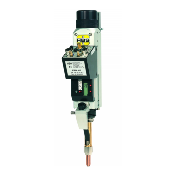
Page 19: Components Of The Automatic Welding Head
All supply lines (welding current cable, control cable, compressed air lines) are plugged into the connection casing (E). Located on the front of the KAH 412 automatic welding head is the feed tube, which can be quickly changed via the pushbutton locking system. The infeed (manual or automatic) of the welding elements takes place via the feed tube in the slot piston with guide sleeve to the chuck. - Page 20 The type plate contains the following information: – Manufacturer – Type – Order No./Serial No. – Date. ©HBS Bolzenschweiss-Systeme GmbH & Co. KG All rights reserved – Reprinting, in whole or in part, only with the approval of the manufacturer...
-
Page 21: Keyboard And Display
10 min. with no movement of the guide piston Changing the measuring unit briefly press the [mm/inch] pushbutton or Zero briefly press the [0/ON] pushbutton ©HBS Bolzenschweiss-Systeme GmbH & Co. KG All rights reserved – Reprinting, in whole or in part, only with the approval of the manufacturer... -
Page 22: Welding Process
Please refer to the original operating manual of the used stud welding unit for the welding procedure. ©HBS Bolzenschweiss-Systeme GmbH & Co. KG All rights reserved – Reprinting, in whole or in part, only with the approval of the manufacturer... -
Page 23: Preparing The Welding Head
‹ Do not connect the welding head to the stud welding unit until it has been prepared. In this way you can avoid any unintentional starting of the welding process. ©HBS Bolzenschweiss-Systeme GmbH & Co. KG All rights reserved – Reprinting, in whole or in part, only with the approval of the manufacturer... -
Page 24: Replacing The Pressure Spring
‹ Make sure that the pointer is situated in the groove guide of the lift adjustment screw. ‹ Tighten the spring adjustment screw. ‹ Attach the rear cap. ©HBS Bolzenschweiss-Systeme GmbH & Co. KG All rights reserved – Reprinting, in whole or in part, only with the approval of the manufacturer... -
Page 25: Adjusting The Working Position
CPW, MPW or PC-C. This ensures dimensional stability of your stud positions. ©HBS Bolzenschweiss-Systeme GmbH & Co. KG All rights reserved – Reprinting, in whole or in part, only with the approval of the manufacturer... - Page 26 The upper edge of the flange must be 2 mm below the upper edge of the workpiece. ©HBS Bolzenschweiss-Systeme GmbH & Co. KG All rights reserved – Reprinting, in whole or in part, only with the approval of the manufacturer...
- Page 27 Select pin stop one level shorter than standard e.g. length of the welding element 12 > pin stop 10 ©HBS Bolzenschweiss-Systeme GmbH & Co. KG All rights reserved – Reprinting, in whole or in part, only with the approval of the manufacturer...
-
Page 28: Equipping The Welding Head
80-10-208 Socket wrench WAF 17 80-40-085 *) Selection according to model and dimensions of the welding element ©HBS Bolzenschweiss-Systeme GmbH & Co. KG All rights reserved – Reprinting, in whole or in part, only with the approval of the manufacturer... -
Page 29: Manual And Automatic Equipment Parts
84-40-561 80-07-789 80-07-765 10.3 80-07-805 10.3 84-50-005 5 x 40 84-40-561 80-07-789 80-07-765 10.3 80-07-805 10.3 84-50-005 ©HBS Bolzenschweiss-Systeme GmbH & Co. KG All rights reserved – Reprinting, in whole or in part, only with the approval of the manufacturer... - Page 30 ‹ When selecting the equipment, take the notices from chapter 10.2 Adjusting the Working Position - Determining the protrusion (see page 26) into account. ©HBS Bolzenschweiss-Systeme GmbH & Co. KG All rights reserved – Reprinting, in whole or in part, only with the approval of the manufacturer...
- Page 31 84-40-561 80-07-789 80-07-765 10.3 80-08-165 10.3 84-50-005 5 x 40 84-40-561 80-07-789 80-07-765 10.3 80-08-165 10.3 84-50-005 ©HBS Bolzenschweiss-Systeme GmbH & Co. KG All rights reserved – Reprinting, in whole or in part, only with the approval of the manufacturer...
- Page 32 ‹ When selecting the equipment, take the notices from chapter 10.2 Adjusting the Working Position - Determining the protrusion (see page 26) into account. ©HBS Bolzenschweiss-Systeme GmbH & Co. KG All rights reserved – Reprinting, in whole or in part, only with the approval of the manufacturer...
- Page 33 ‹ Place the chuck (pos. 6) in the slot piston (pos. 11) and secure it with the retain- ing nut (pos. 7). ©HBS Bolzenschweiss-Systeme GmbH & Co. KG All rights reserved – Reprinting, in whole or in part, only with the approval of the manufacturer...
- Page 34 (pos. 12). Make sure that the trigger pin springs back to the rest position; the feed tube is then correctly inserted and secured. ‹ You can now connect the blue air connection. ©HBS Bolzenschweiss-Systeme GmbH & Co. KG All rights reserved – Reprinting, in whole or in part, only with the approval of the manufacturer...
-
Page 35: Adjusting Welding Parameters
The specifications in the following table are guidelines. ‹ Select the applicable parameters for lift and spring force for your workpiece. ©HBS Bolzenschweiss-Systeme GmbH & Co. KG All rights reserved – Reprinting, in whole or in part, only with the approval of the manufacturer... - Page 36 AlMg3 M6, 6 mm 6 mm, M4 AlMg3 M8, 7.1 mm 7.1 mm, M5 99 000 mF ©HBS Bolzenschweiss-Systeme GmbH & Co. KG All rights reserved – Reprinting, in whole or in part, only with the approval of the manufacturer...
- Page 37 CuZn37 M6, 6 mm 6 mm, M4 CuZn37 M8, 7.1 mm 7.1 mm, M5 99 000 mF ©HBS Bolzenschweiss-Systeme GmbH & Co. KG All rights reserved – Reprinting, in whole or in part, only with the approval of the manufacturer...
- Page 38 AlMg3 M6, 6 mm 6 mm, M4 AlMg3 M8, 7.1 mm 7.1 mm, M5 99 000 mF ©HBS Bolzenschweiss-Systeme GmbH & Co. KG All rights reserved – Reprinting, in whole or in part, only with the approval of the manufacturer...
- Page 39 6 mm, M4 A2-50 M8, 7.1 mm 7.1 mm, M5 can only be used with the automatic version ©HBS Bolzenschweiss-Systeme GmbH & Co. KG All rights reserved – Reprinting, in whole or in part, only with the approval of the manufacturer...
- Page 40 5 mm, M3 AlMg3 M6, 6 mm 6 mm, M4 AlMg3 M8, 7.1 mm 7.1 mm, M5 ©HBS Bolzenschweiss-Systeme GmbH & Co. KG All rights reserved – Reprinting, in whole or in part, only with the approval of the manufacturer...
- Page 41 5 mm, M3 A2-50 M6, 6 mm 6 mm, M4 A2-50 M8, 7.1 mm 7.1 mm, M5 ©HBS Bolzenschweiss-Systeme GmbH & Co. KG All rights reserved – Reprinting, in whole or in part, only with the approval of the manufacturer...
- Page 42 G - Locking bolt for height adjustment H - Height adjustment I - Toggle switch for solenoid ©HBS Bolzenschweiss-Systeme GmbH & Co. KG All rights reserved – Reprinting, in whole or in part, only with the approval of the manufacturer...
-
Page 43: Adjusting Spring Force
The currently applied spring force is shown on the display for spring-force adjustment, in this example 5 mm. ‹ Mount the rear cap. ©HBS Bolzenschweiss-Systeme GmbH & Co. KG All rights reserved – Reprinting, in whole or in part, only with the approval of the manufacturer... -
Page 44: Adjusting The Protrusion
‹ Secure the set value by again tightening the locking bolt. ‹ Use the 0/ON pushbutton to set the display back to 0.00. ©HBS Bolzenschweiss-Systeme GmbH & Co. KG All rights reserved – Reprinting, in whole or in part, only with the approval of the manufacturer... -
Page 45: Adjusting The Lift
‹ Remove weld spatter from the chuck and slot piston. ©HBS Bolzenschweiss-Systeme GmbH & Co. KG All rights reserved – Reprinting, in whole or in part, only with the approval of the manufacturer... - Page 46 ‹ Briefly push the trigger for “0 / ON” to the left to switch the display back on again. ©HBS Bolzenschweiss-Systeme GmbH & Co. KG All rights reserved – Reprinting, in whole or in part, only with the approval of the manufacturer...
-
Page 47: Welding
11 Welding Welding ‹ Work according to the original operating manual of the HBS stud welding unit. Danger if used other than for the intended purpose ‹ Use the welding head only for CD stud welding or ARC stud welding and only in combination with stud welding units from manufacturer: HBS Bolzenschweiss-Systeme GmbH &... -
Page 48: Troubleshooting
In case of no flow: Qualified specialists cable for electrical flow *) Replace welding current cable and/or connecting cable *) ©HBS Bolzenschweiss-Systeme GmbH & Co. KG All rights reserved – Reprinting, in whole or in part, only with the approval of the manufacturer... - Page 49 ‹ Please use the form „Service & Support“ in the annex to send in the stud welding unit or welding head. ©HBS Bolzenschweiss-Systeme GmbH & Co. KG All rights reserved – Reprinting, in whole or in part, only with the approval of the manufacturer...
-
Page 50: Maintenance And Care
The following maintenance recommendations cannot account for the unique situati- on at your site. ‹ For this reason, you should create in-house maintenance instruc- tions. ©HBS Bolzenschweiss-Systeme GmbH & Co. KG All rights reserved – Reprinting, in whole or in part, only with the approval of the manufacturer... - Page 51 Trained automatic welding personnel head Clean and grease With Amblygon Trained the piston rod TA 15/2 personnel ©HBS Bolzenschweiss-Systeme GmbH & Co. KG All rights reserved – Reprinting, in whole or in part, only with the approval of the manufacturer...
-
Page 52: Inspection And Tests
‹ Clean the type plates in the event of soiling. ‹ Replace any type plates that are damaged or no longer legible. ©HBS Bolzenschweiss-Systeme GmbH & Co. KG All rights reserved – Reprinting, in whole or in part, only with the approval of the manufacturer... -
Page 53: Removing Equipment
‹ Pay particular attention to soiling in parts 8, 9 and 14. Soiling can prevent studs from being transported into the chuck. ©HBS Bolzenschweiss-Systeme GmbH & Co. KG All rights reserved – Reprinting, in whole or in part, only with the approval of the manufacturer... -
Page 54: Dismounting The Welding Head
‹ Disconnect all connections on the welding head. ‹ Loosen the screw for the dovetail mount (pos. 198). ‹ Remove the welding head. ©HBS Bolzenschweiss-Systeme GmbH & Co. KG All rights reserved – Reprinting, in whole or in part, only with the approval of the manufacturer... -
Page 55: Changing The Battery For The Electronic Display Unit
‹ Remove the double-sided adhesive pad (pos. F). ‹ Slide the used battery (pos. 146) out to the side. ©HBS Bolzenschweiss-Systeme GmbH & Co. KG All rights reserved – Reprinting, in whole or in part, only with the approval of the manufacturer... - Page 56 After installing the welding head in a CNC system, the position of the welding head must be checked and re-aligned if necessary. For this purpose, we recommend using the HBS adjustment set for the wel- ding head position. ‹ Never dispose of used batteries in household waste.
-
Page 57: Storage
‹ Dispose of the welding head only via the manufacturer or a specialist disposal company. ‹ Never dispose of the welding head in the domestic refuse. ©HBS Bolzenschweiss-Systeme GmbH & Co. KG All rights reserved – Reprinting, in whole or in part, only with the approval of the manufacturer... -
Page 58: Declaration Of Incorporation Of Partly Completed Machinery
Declaration of Incorporation of partly completed Machinery Declaration of Incorporation of partly completed Machinery to Directive 2006/42/EC, Annex II 1 B (Original Declaration of Incorporation) Herewith the manufacturer HBS Bolzenschweiss-Systeme GmbH & Co. KG Felix-Wankel-Strasse 18 P.O. Box 13 46 85221 Dachau GERMANY... -
Page 59: Service & Support
Service & Support Service & Support With the return please attach a copy of the filled out form together with the repair number given by HBS! Repairs without repair number will not be processed. Repair number (given by HBS) Company:... -
Page 60: Index
......12 ©HBS Bolzenschweiss-Systeme GmbH & Co. KG All rights reserved – Reprinting, in whole or in part, only with the approval of the manufacturer... - Page 62 HBS Bolzenschweiss-Systeme GmbH & Co. KG Felix-Wankel-Strasse 18 • 85221 DACHAU • GERMANY Phone +49 8131 511-0 • Fax +49 8131 511-100 • E-mail international@hbs-info.com www.hbs-info.com...
Need help?
Do you have a question about the KAH 412 and is the answer not in the manual?
Questions and answers