Advertisement
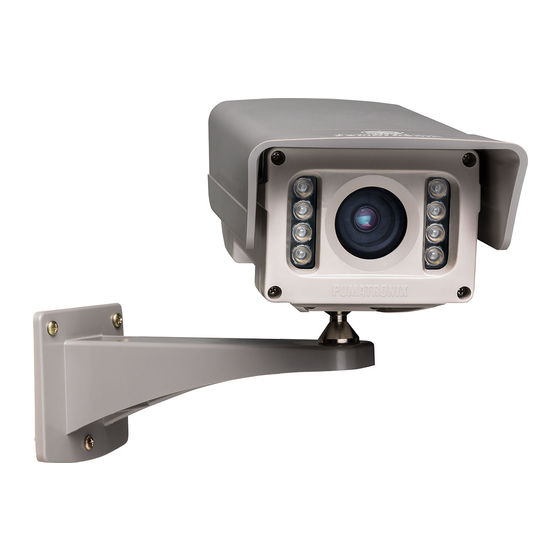
Built-in
illuminator
This equipment has a set of lenses that is sensitive to
mechanical impacts such as drops and severe external
vibrations.
12-way
Multi-way Cable
Risk of Oxidation: The electrical and signal connections
made in the ITSCAM VIGIA+ bundle and the data
network cable must be protected in a terminal box or
similar structure to prevent oxidation of the connections
and unwanted infiltration of liquids into the bundle.
* Use the Ethernet cable to connect the ITSCAM VIGIA+ to the local
network and optionally to power the device.
* Use the
12-way multi-way cable
the power source and to signal input equipment for physical triggering, such
as an inductive loop or an optical barrier, for example.
* Use the
output of the
connect the ITSCAM VIGIA+ to an illuminator or to equipment that
be
control
ed
, such as barriers or gates.
1. Use the Ethernet cable for the network connection, with an RJ-45
connector following the ANSI/TIA-568A standard pinout.
ITSCAM VIGIA+
Bracket
2. Make the connections of the
color
ways
of the
12-way multi-way cable
the table:
TERMINAL AND COLOR
4
Violet
5 White
Ethernet
Cable
12-way
Multi-way Cable
inputs to connect the ITSCAM VIGIA+ to
12-way multi-way cable
(orange and yellow),
Serial Port
signals in the
Violet
and
, considering the signals detailed in
MULTI-WAY CABLE
SIGNAL
RS232_ X2
R
RS232_ X2
T
Ethernet
Cable
Rx2
Tx2
GND
09/05/2022
Revis
ion
1.0
to
needs
to
White
Advertisement
Table of Contents

Related Manuals for PUMATRONIX VIGIA+


Summary of Contents for PUMATRONIX VIGIA+
- Page 1 * Use the Ethernet cable to connect the ITSCAM VIGIA+ to the local network and optionally to power the device. * Use the 12-way multi-way cable inputs to connect the ITSCAM VIGIA+ to the power source and to signal input equipment for physical triggering, such as an inductive loop or an optical barrier, for example.
- Page 2 9. Access the ITSCAM VIGIA+ interface in a Google Chrome browser (version 85 or higher) with the factory default data: 5. Use a 12Vdc or 24Vdc power supply.* 3. Make the signal connections on ways numbered 3, 4, 9, and 10 of the *Models with sensor S01 or S04 allow the power supply 192.168.0.254 12-way multi-way cable, which can be used to receive signals from a loop, or...
- Page 3 às especificações de instalação, é recomendado or 7). respecting the maximum angle limit of 45° for vertical inclination, avoiding consultar o Suporte Técnico da Pumatronix. significant deformations in the images. Carry out the NETWORK INTERFACE PARAMETERIZATION Steps 8 to 15).
- Page 4 * Access in the Product Manual the step-by-step installation of firmware Pumatronix is not responsible for the finalities, use and treatment of updates, which can be done through the web interface or the Pumatronix the images captured, and the control of the information and forms of software.
Need help?
Do you have a question about the VIGIA+ and is the answer not in the manual?
Questions and answers