
Related Manuals for Mobileye 8 Connect


Summary of Contents for Mobileye 8 Connect
- Page 1 Technical Installation Guide (4G) v1.7 November Mobileye 8 Connect Technical user guide (4G) v1.9 Mobileye 8 Connect...
-
Page 2: Table Of Contents
Analog Installation Scheme Connection Description 5.1 Intro 5.2 Main unit connections (CAB000400 Rev3.3) 5.3 Mobileye 8 Connect signals cable (CAB000371 Rev6.3) 5.4 Ferrite 5.4.1 Ferrite for Power Sources -Model 1 (ITM000786) 5.4.2 Instructions for power sources (CAB000371) 5.4.3 Ferrite for Power Sources -Model 1 (ITM000777) 5.4.4 Instructions for power sources (CAB000371) - Page 3 Technical Installation Guide (4G) v1.9 4G Cable Ferrite Installation Instructions for 4G cable Ferrite installation Mobileye 8 Connect 4G Connection Scheme Installation & Calibration 8.1 Back-Cover removal 8.2 Communication / Connection phase 8.3 System Calibration 8.3.1 Login 8.3.2 Login 8.3.3 Vehicle Selection...
- Page 4 Technical Specification 19.1 Mobileye® 8 connect™ – 4G | Technical Specification Sheet 19.2 Mobileye® 8 connect™ – 4G | Display unit Specification Sheet 19.3 Mobileye® 8 connect™ – 4G | Cellular Module Specification Sheet 19.4 Mobileye® 8 connect™ – 4G | GNSS Technical Specification 19.5...
-
Page 5: Warnings
‘urgent’ the warning. Mobileye 8 Connect is not an automated driving system. It does not replace the driver nor allow the driver to be any less vigilant or alert to the road than he/she would otherwise be. -
Page 6: Installation & Safety Instructions
Do not transfer Mobileye 8 Connect to another vehicle after installation. The Mobileye 8 Connect GSM Nano SIM card will work only with the Mobileye 8 Connect unit with which it is supplied; do not use the SIM for other purposes or with other Mobileye 8 Connect units. -
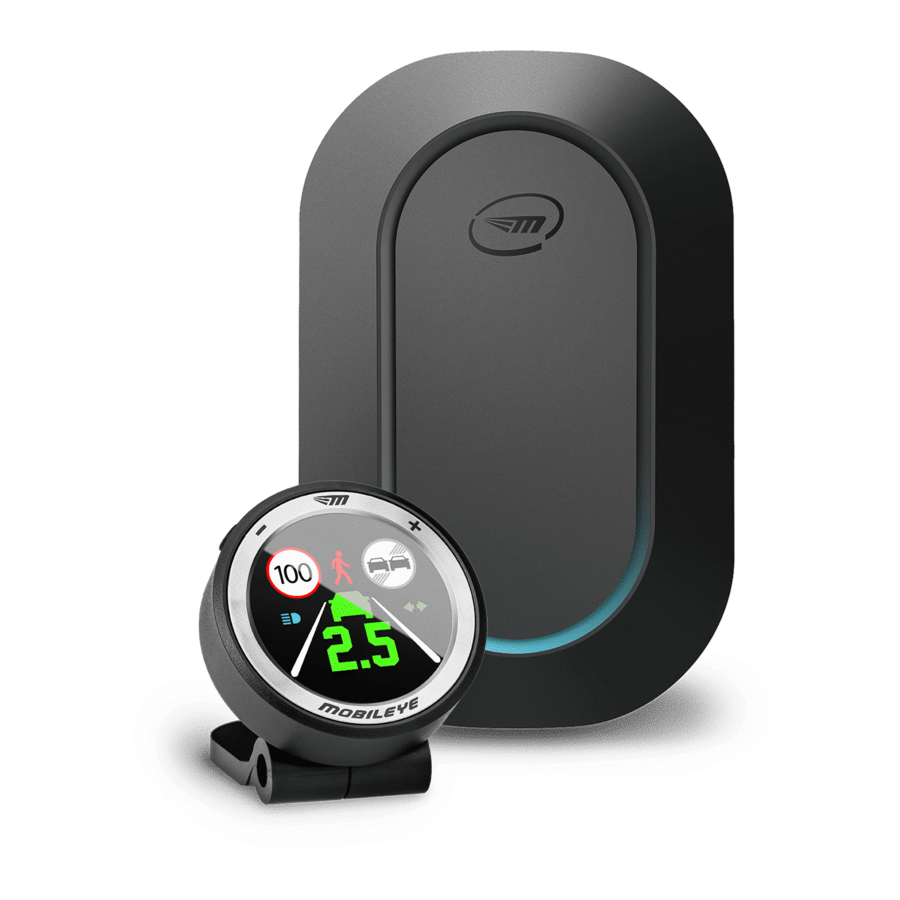
Page 7: Components Overview
ASY0000000000805 PAC0000AJMODEM4G PAC0000CHMODEM4G PAC0000EUMODEM4G 4G Modem PAC0000INMODEM4G PAC0000NAMODEM4G PAC0000LAMODEM4G ASY000130 EyeWatch 3 Display unit – EyeWatch EyeWatch 8 (Optional) PAC0000000000EW8 Main cable CAB000400 Rev3.3 GPS Cable & Module CAB000402 Signals cable CAB000371 Rev6.3 CAN Reader CAB000302 Rev.0.3 Mobileye 8 Connect... - Page 8 TACS00003 (reference point) and for calibration calculation The Mobileye EyeNET and TAC are not part of the Mobileye 8 Connect kit and are sold separately. Mobileye 8 Connect...
-
Page 9: Software Download & Installation
Please make sure you have Administrator Privileges before installing the Mobileye IC application, if not, please contact your IT department for further assistance. To keep the most up to date version of the IC application, login with your login details to enable to automatic update. -
Page 10: Connection Scheme
Technical Installation Guide (4G) v1.9 4. Connection Scheme CAN-bus Installation Scheme Mixed Installation Scheme (Analog + CAN-bus) Mobileye 8 Connect... -
Page 11: Analog Installation Scheme
Technical Installation Guide (4G) v1.9 Analog Installation Scheme Mobileye 8 Connect... -
Page 12: Connection Description
5.3 Mobileye 8 Connect signals cable (CAB000371 Rev6.3) The Mobileye 8 Connect signals cable splits into a few cables which connect to the vehicle power source, to the vehicle CAN-bus (Via CAN Reader connector) , to the vehicle analog speed signal, to the vehicle high-beams (for IHC), to one of the vehicle’s analog signals if required (or both analog left- and right-turn indicator signals via diode), to the EyeWatch display unit (via 4 pin male connector labeled as "EyeWatch"... - Page 13 3 party device RS-485 High Green 4pin EyeWatch 3 RS-485 Low White 4pin EyeWatch 3 RS-485 GND Black 4pin EyeWatch 3 RS-485 5V DC 4pin EyeWatch 3 Table 2: Mobileye 8 Connect analog signals cable connection Mobileye 8 Connect...
-
Page 14: Ferrite
Place both Mobileye BAT+ wire and Ignition wire (CAB000371) together inside the first Ferrite. 2. L ocate the Ferrite 5cm from the Mobileye CAB000371 label 3. Wrap the BAT+ Ignition wires through the Ferrite 2 times around the outside of the Ferrite 1 times, as shown in the figures 4. -
Page 15: Ferrite For Power Sources -Model 1 (Itm000777)
5. Lock the Ferrite 6. Open the second Ferrite using the supplied Key or small flat screwdriver 7. Place the Mobileye GND wire in the second Ferrite ( locate the Ferrite filters 5cm from the Mobileye CAB000371 label). 8. Wrap the GND wire through the Ferrite 4 times and around the outside of the Ferrite 3 times, as shown in the figures 9. -
Page 16: Eyewatch 3 - Display And Control Unit (Cab000087) -Option
EyeWatch unit EyeWatch 8 – display and control unit (CAB000401) -OPTION 2 The EyeWatch 8 is connected to the Mobileye 8 Connect signals cable with the EyeWatch male connector (P1) to the Signals cable EyeWatch 8 female connector (P2). Table 3: EyeWatch connections... -
Page 17: Can Reader - Cab000302
Power sources and signals cable (CAB0003002) (CAB000371) EyeNET – (EYENET0001 / CAB000613 The Mobileye 8 Connect service port female connector (P2) is used to connect to the Mobileye EyeNET short cable male connector labeled “MOBILEYE8 SIDE” (J5). Wire name Wire color... -
Page 18: Connection Description
(Accessory) position or ignition ON. Make sure the car headlights and/or any other power consuming devices/applications, e.g. air conditioning, are turned off during Mobileye 8 Connect installation to prevent battery drainage. Please ensure to identify the Mobileye 8 Connect cables according to table below. Identified vehicle’s signals Wires label... -
Page 19: Eyewatch Installation
4. Remove the transparent protecting covering from the display surface 5. Insert the EyeWatch cable (CAB000087/CAB000401) behind the vehicle trimmings so that it reaches the EyeWatch connector of the Mobileye 8 Connect cable (CAB000400) Mobileye 8 Connect... -
Page 20: Mobileye 8 Connect Main Unit (Camera) Installation
Maximum height for camera location is 1.8 meter (5.9 feet). In extreme cases and upon approval of Mobileye support team, it is possible to install the camera above 1.8 meters BUT this will void any REM data which can affect the project target. - Page 21 8 Connect cable (CAB000400) behind the vehicle trimmings so that it reaches all vehicle signals (it is recommended that you hang the Mobileye 8 Connect main unit on the rear-view mirror or place it on the dashboard before passing the cable behind the vehicle trimmings).
-
Page 22: Installing The Mobileye 8 Connect 4G Modem
Technical Installation Guide (4G) v1.9 6.5 Installing the Mobileye 8 Connect 4G modem Mobileye 8 Connect uses an external 4G Modem for better cellular coverage. The modem can be placed below the dashboard or any other location with enough space to accommodate it as long as there are not any Metal parts above the modem that may interrupt the reception. -
Page 23: G Cable Ferrite Installation
Technical Installation Guide (4G) v1.9 2nd cable coming out of Mobileye camera for external modem no bottom exit for modem cable - only from Up position 4G Cable Ferrite Installation Before making the power connections, extract the Fuse from the Fuse holder and add it... -
Page 24: Mobileye 8 Connect 4G Connection Scheme
Technical Installation Guide (4G) v1.9 2. Wrap the cable through the Ferrite 2 times and around the outside of the Ferrite 1 time 7.2 Mobileye 8 Connect 4G Connection Scheme Note: The Ferrite size and shape may vary different between different Ferrite models. -
Page 25: Installation & Calibration
Technical Installation Guide (4G) v1.9 Installation & Calibration 8.1 Back-Cover removal As part of the Mobileye 8 Connect calibration process, the camera angle must be adjusted as outlined below. To access the camera angle adjustment`s screw you must remove the main unit’s back cover. -
Page 26: Communication / Connection Phase
Technical Installation Guide (4G) v1.9 8.2 Communication / Connection phase Mobileye 8 Connect service port interface is used to communicate with the Mobileye system. The EyeNET adapter enables fast connection between the Mobileye 8 Connect and Mobileye software running on a computer for system calibration and configuration Figure 1 –... -
Page 27: System Calibration
Technical Installation Guide (4G) v1.9 8.3 System Calibration 8.3.1 Login Open the Installation Center application on your computer and login using your personal login details youremail@email.com *********** → Click "Login" to continue Mobileye 8 Connect... -
Page 28: Login
It is possible to continue and open the IC Wizard application directly from the vehicle database. If you are already connected to a Mobileye 8 Connect system and have completed the physical connections, you may skip the "vehicle database" and click the "wizard" button to immediately start the installation... - Page 29 Technical Installation Guide (4G) v1.9 When clicking the "Wizard" button you must be physically connected to a Mobileye 8 Connect system and the system power must be on to continue the calibration process. You will have an option to browse and choose the correct profile of the vehicle you are installing during a standard Wizard run as well.
-
Page 30: Vehicle Selection
In the event the vehicle into which you are installing is not in the vehicle database, you can either try a similar profile or contact Mobileye support for help with creating a new profile. → Click "Go to App" to continue... -
Page 31: Connection To Seeq
Technical Installation Guide (4G) v1.9 8.3.4 Connection to SeeQ The app will check: communication status with Mobileye’s system and provide system information such as: Connection status System serial number System firmware version Physical connection and communication of the below peripherals with the app ... -
Page 32: Vehicle Information
Technical Installation Guide (4G) v1.9 8.3.5 Vehicle Information Enter the license number, VIN number and choose the country from the dropdown menu. → Click "Next" to continue Mobileye 8 Connect... -
Page 33: Vehicle Information
The software will remember and display all the vehicle and profile information you chose earlier. You can always choose a new profile or modify your earlier selection at this time. Click → "Burn selected profile" to burn and save the profile data into the Mobileye system. ... -
Page 34: Analog Installation
If you don’t know the vehicle VSS rate, set the value to 5000, Burn the profile as set and check the Vehicle speed vs the Mobileye Installation Center shown speed, if necessary, please adjust the rate so the speed shown will be accurate. -
Page 35: Signal Test
Activate each signal and an icon will be shown when it is detected by the Mobileye system. Speed signal verification - drive and confirm speed indication in the Mobileye setup wizard approximately matches the speed of the car shown by the speedometer. ... -
Page 36: Signal Test Troubleshooting
Try to switch CAN High and CAN Low connections- try to flip the CAN Sensor on the CAN wires and reset test again. Make sure you connected to the CAN wires as described in the Mobileye Vehicle Database. -
Page 37: Calibration
TAC should be 90 cm from ground or 165 cm if the TAC is opened and flipped to high level (depending on the camera height). Mount the camera on the windshield according to Mobileye’s guidelines as follows: Mobileye 8 Connect... -
Page 38: Step 2 - Camera Attachment
TAC target. If the camera is mounted off-center, make sure this offset is reflected in the yellow line location on the TAC target. Center 5cm to the right 10cm to the right Mobileye 8 Connect... -
Page 39: Gps Attachment
Make sure the GPS is facing up and attached in cleared area on the windshield. The Mobileye GPS module can be attached at one of vehicle windshield corners in area not covered by the wipers and/or without any other Metal obstructions. -
Page 40: Gps Attachment Location Allowed Areas
Technical Installation Guide (4G) v1.9 9.2 GPS attachment location allowed areas Angled Windshield: GPS attachment location allowed Green – – GPS attachment location not allowed Flat Windshield: GPS attachment location allowed Green – – GPS attachment location not allowed Mobileye 8 Connect... -
Page 41: Step 4 - Measurements
Entering any measurement that is not in the acceptable range or not in the correct format will be highlighted in red and will not let you continue to the next step Enter each vehicle measurement in the correct field: Camera height Measure the camera height from the camera lens to the ground. Mobileye 8 Connect... - Page 42 For vehicles without front engine hood, Measure and enter the true distance from camera to front bumper. Wheels Base (width of the vehicle wheels) Measure the distance between the outer edges of the front wheels. Mobileye 8 Connect...
- Page 43 Left & Right should be measure from the outside of the vehicle but should be insert to the software as driver perspective sides (see Left &Right on the illustration bellow. Right Left Vehicle Height Measure the distance from ground to the top of the vehicle. Mobileye 8 Connect...
- Page 44 Measure the GPS unit distance from Left & Right windshield edge. PLEASE NOTE: Left & Right should be measure from the outside of the vehicle but should be insert to the software as driver perspective sides (see Left & Right on the illustration bellow. Right Left Mobileye 8 Connect...
-
Page 45: Step 5 - Camera Angle Adjustment
RED line will be parallel to the height mark on the TAC. Once the red line in the image is lined up with the marking you placed on the TAC, tighten the camera angle adjustment screw. Mobileye 8 Connect... -
Page 46: Step 6 - Car Hood
If no car engine hood is present in the image, car hood value should remain at the default value of -120 11.2 Step 7 – Calibration Once all these measurements have been entered, 2 calibration steps are required: Far TAC Close TAC 1 Meter Close TAC Far TAC Mobileye 8 Connect... - Page 47 Press “Close TAC” for close TAC calculation. Far TAC After the close TAC calculation has been successfully completed, a pop-message will appear. Move the TAC 1-meter back Press “OK” and. Press “Far TAC” for far TAC calculation. Mobileye 8 Connect...
- Page 48 1. FOE X optimal value is 0 ±15 2. FOE Y optimal value is 0 (±10) 3. Calculated height- up to 3cm differences 4. Roll – up to 2° If calibration results meet the minimum requirements mentioned above, calibration is completed, click “Finish” Mobileye 8 Connect...
-
Page 49: Validation
Upon completion of the system calibration, the installer MUST validate all peripherals are functional and valid using the new validation tool which can be found as part of Mobileye IC prior to releasing the vehicle after the installation. 10.2 Operation... - Page 50 GPS signal or cellular network is not available, the test status of the relevant component will pass but no valid data will be displayed. If any of the peripherals found faulty, the Mobileye system must be replaced to complete the installation.
-
Page 51: Appendix A - 4G Modem
Technical Installation Guide (4G) v1.9 13. Appendix A – 4G Modem 13.1 Modem Status 4G MODEM LED BEHAVIOR Status CONSTANT GREEN SW ready. CONSTANT ORANGE No SIM and/or no network FLASHING ORANGE Network and communication OK Mobileye 8 Connect... -
Page 52: Technical Spec
TS 27.005, 27.007 and Telit Custom AT commands LTE FDD Cat.4, 3GPP release 10 compliant Telecommunications standards LTE FDD Cat.1. 3GPP release 9 compliant Serial interface UART (up to 3Mbps) Power supply Sim voltage 1.8V Nano SIM 10mm X 12.5mm x 1.2mm Sim size Mobileye 8 Connect... -
Page 53: Appendix A - Can Reader
The Mobileye 8 Connect CAN-Reader is a new, non-intrusive solution for CAN-bus connection. No more wrong connections, warranty violations or liability issues. The Mobileye CAN-Reader will allow you to better handle a CAN-bus reading by simply placing the Mobileye CAN-sensor on the vehicle CAN-bus wires without any wire cutting or pinching. -
Page 54: Appendix B - Up/Down Configuration
15. Appendix B – up/down configuration 15.1 General Mobileye 8 Connect is based on a smart camera, which is installed on the vehicle’s front windshield. To suit all vehicle models (cars, trucks, buses) the smart camera main cable (CAB000400) has two configurations: up and down. - Page 55 Technical Installation Guide (4G) v1.9 Using a Philips screwdriver, unscrew the 3 screws and remove the main back cover 3. Using a Philips screwdriver, unscrew to remove the main chassis from the frame Mobileye 8 Connect...
- Page 56 Do not unscrew the upper left and lower right screws. This will void the warranty! 5. Remove the main cable connector and connect it to the desired configuration Camera up position Camera down position 6. Once completed, reassemble all system components tightening the screws. Mobileye 8 Connect...
-
Page 57: Appendix C - Eyenet Holder (Asy000451)
Technical Installation Guide (4G) v1.9 16. Appendix C – EyeNET Holder (ASY000451) 16.1 Intro The EyeNET holder used to hold the EyeNET and maintain a stable communication with the Mobileye system. 16.2 Component Overview MEC000950 SCR000120 16.3 Assembly Attach the EyeNET holder on top of the system`s metal body. - Page 58 Technical Installation Guide (4G) v1.9 Use to 2x screws to hold the EyeNET Route the EyeNET flat cable trough the designated gap and connect it in both ends to the Mobileye system and the EyeNET and continue with the calibration process Mobileye 8 Connect...
-
Page 59: Appendix D - Calibration Tool
17.1 Intro The Calibration Tool allows to recalibrate the ME8 units without deactivation vehicle profile change such as windshield replacement. 17.2 Instructions 1. To use the Calibration Tool run the app from the Installation Center main screen Mobileye 8 Connect... - Page 60 2. The tool will check communication with the system and display the system s/n and FW version and display the status of each component. 3. The camera attachment, measurements and calibration slide will show. To attach, measure and calibrate, please refer to pages 32-42. Mobileye 8 Connect...
-
Page 61: Troubleshooting
2. Installation issues: If signal test fails, check that: You connected the correct CAN wires as instructed in the Mobileye Vehicle DB. Make sure you selected the correct profile for the vehicle. If necessary, try to use another profile or proceed to CAN sniffing for a new profile creation. -
Page 62: Technical Specification
Technical Installation Guide (4G) v1.9 19. Technical Specification 19.1 Mobileye® 8 connect™ – 4G | Technical Specification Sheet Mobileye® 8 Connect Main Unit PHYSICAL CHARACTERISTICS FULL SYSTEM ELECTRICAL CHARACTERISTICS Input voltage Length 120mm 10-36VDC Width (without lens) 78mm Input current (full operation) 1A @ 12V, 0.5A @ 24V... -
Page 63: Mobileye® 8 Connect™ - 4G | Display Unit Specification Sheet
Technical Installation Guide (4G) v1.7 19.2 Mobileye® 8 connect™ – 4G | Display unit Specification Sheet EyeWatch Display Units PHYSICAL CHARACTERISTICS EYEWATCH 3 EYEWATCH 8 Diameter 49mm Width 84.5m 25mm Depth 66mm (leg open) Leg closed: 34mm Leg open: 73mm... - Page 64 Technical Installation Guide (4G) v1.7 19.3 Mobileye® 8 connect™ – 4G | Cellular Module Specification Sheet 4G Cellular Module PHYSICAL CHARACTERISTICS Model Telit LE910C1 Length 182mm Width 55mm (slimmest); 78.6mm in connector area (peak) Height 22MM Modem unit: 121.9g Weight Modem cable: 119.3g...
-
Page 65: Mobileye® 8 Connect™ - 4G | Gnss Technical Specification
Technical Installation Guide (4G) v1.7 19.4 Mobileye® 8 connect™ – 4G | GNSS Technical Specification RECIEVER TYPE Receive and track multiple systems Support satellite: GPS, GLONASS, BeiDou and QZSS signals FEATURES Frequency of time pulse signal 0.25 Hz…10 MHz...
Need help?
Do you have a question about the 8 Connect and is the answer not in the manual?
Questions and answers