Table of Contents
Advertisement
Quick Links
Advertisement
Table of Contents

Related Manuals for Unipro UniGo One kit 1


Summary of Contents for Unipro UniGo One kit 1
- Page 1 UniGo One Laptimer User Guide...
-
Page 2: Important Safety Instructions
Important safety instructions S a f e t y PLEASE READ THE SAFETY INSTRUCTIONS CAREFULLY • Read the instructions. • Keep these instructions. • Follow all instructions. • Be careful not to drop it on the ground. • Do not leave it under heavy objects. •... -
Page 3: Table Of Contents
Contents C o n t e n t s IMPORTANT SAFETY INSTRUCTIONS ENTERING TEXT CONTENTS EVENT SETUP COPYRIGHT AND ACKNOWLEDGMENTS EVENT NAME OUTING TYPE SALES AND SERVICE IN DENMARK TRACK SETUP INTERNATIONAL DEALERS TRACK DATABASE DESIGN AND PRODUCTION AUTO TRACK SELECT ABOUT THIS USER GUIDE COUNTRY DISCLAIMER... -
Page 4: Contents
Contents C o n t e n t s RUN MODE DATA HOLD TIME LAP TIME DISPLAY RUN MODE 1 SPLIT TIME DISPLAY RUN MODE 2 BETTER / WORSE FEEDBACK MENU RUN MODE 3 BETTER / WORSE TRIGGER ANALYZE MODE UNIGO SETUP SESSION SELECT RUN MODE SCREENS... -
Page 5: Copyright And Acknowledgments
Unipro ApS. The UniGo One Laptimer was designed by Palle Schultz, Denmark: www.palleschultz.dk Unipro reserves the right to make changes and improvements to any of the products described in this document without prior notice. Part numbers: 03-05-001 UniGo One kit 1... - Page 6 This page was intentionally left blank.
-
Page 7: Introduction
This antenna design is less sensi- UniGo One combines many new ideas not seen tive to movement of the antenna, and ensures before in a Unipro Laptimer: a perfect reception of GPS signal all the time. • Big high resolution display with gray tones. -
Page 8: Overview
Overview I n t r o d u c t i o n fast charge. The fuel gauge will give precise Please note that this user guide is intended for information on capacity left in percent, and UniGo One only. even time to empty calculation. -
Page 9: Specifications
Data upload USB full-speed with included USB cable, Wi-Fi or BLE Buttons 4 software defined with icons Software included Unipro Analyser analyze software. Both Windows and Mac version Casing Lightweight plastic Waterproof Dimensions 136.7 x 89.7 x 18.3 / 30.4 mm (5.38” x 3.53” x 0.72”/1.20”) Weight 350 g (12.35 ounces)**... -
Page 10: Examples
Examples I n t r o d u c t i o n... -
Page 11: Installing The Laptimer
I n s t a l l i n g t h e L a p t i m e r Installing the Laptimer A good installation is key to get good and reliable operation of UniGo. Read this installation guide and learn how to: Install the Laptimer, attach cables and sensors and see how to mount it all on the go-kart. -
Page 12: Connecting Rpm Wire
I n s t a l l i n g t h e Installation L a p t i m e r RPM wire attached with cable ties. UniGo mounted at the correct distance to the steering wheel. The RPM wire needs to run all the way from the Laptimer to the engine on the back. -
Page 13: Running Cables
I n s t a l l i n g t h e Installation L a p t i m e r RUNNING CABLES The installation of the Laptimer should be seen as a permanent installation on the go-kart and the time to run the cable in a nice way is time well spend. -
Page 14: Water Temperature
I n s t a l l i n g t h e Installation L a p t i m e r WATER TEMPERATURE The water temperature sensor is typically mounted in the T-junction that goes into the cooling water hose. First mount the sensor in the T-junction and then mount the T-junction the hole. -
Page 15: Exhaust Temperature
I n s t a l l i n g t h e Installation L a p t i m e r Cylinder head temperature sensor mounted below the spark plug. Before mounting the cylinder sensor, remove the washer from the spark plug. EXHAUST TEMPERATURE The exhaust sensor is mounted in the exhaust Drill a ø4.5 mm hole for the sensor through... - Page 16 I n s t a l l i n g t h e Installation L a p t i m e r Exhaust sensor mounted with a big soft bend on the cable. Make sure the cable is not touching the ex- haust pipe and make a soft bend on the cable like shown on the picture.
-
Page 17: Quick Guide
Q u i c k G u i d e Quick Guide Read the Quick Guide and learn how to use the basic functions of the UniGo One: Turn UniGo One on and off, start logging data, analyze them on UniGo One and transfer them to a computer with the included USB cable or Wi-Fi. -
Page 18: Turning Unigo On
UniGo start by turning on the backlight at 25% and show a Unipro splash screen. This is BUILT-IN HELP showing as fast as it is possible, and it will stay When you move around in menus, UniGo will there until UniGo is fully booted. -
Page 19: First Setup
Quick guide Q u i c k G u i d e Typically run mode 1 when driving. Example on the help text describing the current selection. There is not much you can do in run mode ex- cept concentrating on driving! You will be able to change between three predefined layouts FIRST SETUP by pressing the mode button ( ). -
Page 20: Transfer With Usb
Another important screen is the lap and split times screen. TRANSFER WITH USB CTRL+ALT+DELETE It is very easy to transfer data to the Unipro Analyser program. Just insert the included Because the battery is inside UniGo One and USB/charge cable in the top connector (named the box is sealed, there is no way of ”power cy-... -
Page 21: Onfiguring The Aptimer
C o n f i g u r i n g t h e L a p t i m e r Configuring the Laptimer This chapter will learn you all about the configuration of UniGo One. Entering setup, most often settings, and every single setting. A correct setup is essential for the maximum performance of your Laptimer so make sure to read this chapter carefully. -
Page 22: Entering Text
C o n f i g u r i n g Setup mode t h e L a p t i m e r ENTERING TEXT from the popup menu. You always use the same way to enter text in The Backspace menu line is only visible if UniGo. -
Page 23: Event Setup
UniGo One can use two different track databases. Factory tracks are all the tracks that OUTING TYPE Unipro made and this is a growing database Text missing. with more and more tracks. The Unipro Analyser program is able to update the factory tracks loaded onto UniGo One. -
Page 24: Track Name
C o n f i g u r i n g Setup mode t h e L a p t i m e r KART SETUP Use the up ( ) and down ( ) buttons to move around in the list and press the ok The kart menu contains all the settings related button ( ) to select a track. -
Page 25: Counter No
C o n f i g u r i n g Setup mode t h e L a p t i m e r COUNTER no. NUMBER OF GEARS The counter number 1 - 5 menu contains each When driving a gear kart, you need to enter of the tire wear counters. -
Page 26: Engine Setup
C o n f i g u r i n g Setup mode t h e L a p t i m e r ENGINE SETUP TIMER no. The line with the engine timer is used to see The engine menu contains all the settings the timer value and manually adjust it. -
Page 27: Rpm Delta
RPM limiter used in the RPM ignition sys- Text missing and feature not implemented yet. tem. Sometime there is a wish to actually see the drop-outs in the Unipro Analyser program. By enabling this setting, an extra unfiltered RPM channels is logged beside the normal RPM channel. -
Page 28: Sensors Setup
C o n f i g u r i n g Setup mode t h e L a p t i m e r SENSORS SETUP FEEDBACK SETUP Text missing. The feedback menu contains all the settings related to the feedback on UniGo. FLEX INPUT WARNING LEDS MENU It is possible to connect a sensor directly to... -
Page 29: Led Brightness
C o n f i g u r i n g Setup mode t h e L a p t i m e r This illustration shows the warning LED setting in a graphical way. Warning above is the maximum value. -
Page 30: Data Hold Time
C o n f i g u r i n g Setup mode t h e L a p t i m e r Delta time: When passing the start/finish line number is shown in the display. The delta split the delta time is shown. -
Page 31: Unigo Setup
C o n f i g u r i n g Setup mode t h e L a p t i m e r UNIGO SETUP numbers on the screen. The contrast can be set to a value between The UniGo menu contains all the settings -15 and +15. -
Page 32: Set Date
C o n f i g u r i n g Setup mode t h e L a p t i m e r 12-hour clock: If the time format is set to a setting you can chose between the two. 12h clock, then you can chose between am and pm here. -
Page 33: Wi-Fi Setup
Laptimer from the have a lot of Wi-Fi running, you should try to Unipro Analyser program. select a channel that is not used by the other There are no settings for client mode. You networks. - Page 34 C o n f i g u r i n g Setup mode t h e L a p t i m e r...
-
Page 35: Reference Guide
R e f e r e n c e G u i d e Reference Guide In the reference guide you can find detailed information about all features and functions of the UniGo. To get the most from your UniGo, we recommend that you read this guide in full. -
Page 36: Four Buttons
R e f e r e n c e Operating UniGo G u i d e FOUR BUTTONS for long battery life (typically more than 40 hours). For easy operation we made six buttons on UniGo. They are clearly marked with a small Low battery symbol icon, but here is the basic description of each When the batteries reach 5% remaining... -
Page 37: Turn Unigo Off
The startup screen will show an animated Unipro logo and the owners name. It is possible to add your own logo instead of the Unipro version. Power off screen when holding down the top right button. -
Page 38: Shift Light
R e f e r e n c e Operating UniGo G u i d e Each LED is totally programmable and flexible. information. Please see how to do it under ”WARNING LED SETUP” on page 28. The LEDs can either be constant on, blink slowly or blink fast. -
Page 39: Home Screen 1
Home screen with information on UniGo. of the remaining capacity remaining on the battery. The status shows the following If no driver name is entered, it will show states: discharge, pre-charge, charge and fully “Unipro ApS” instead. charged. The battery temperature is important... -
Page 40: Run Mode 2
R e f e r e n c e Operating UniGo G u i d e because a Li-Ion battery can only be charged if inverted text. the temperature is between 0 and 40 °C. Run mode 1 provides four different data channel values at the same time. -
Page 41: Run Mode 3
R e f e r e n c e Operating UniGo G u i d e SESSION SELECT text next to the value will help you identify the channel. UniGo logs data into sessions. Each The bottom line will show the last lap maxi- session contains all the information about the mum value for the two channels. -
Page 42: Lap And Split Times
R e f e r e n c e Operating UniGo G u i d e values for that lap. The delta time compared to the best lap time will be shown all the time. Overview screen with the most important information for the 3 best laps. -
Page 43: Min/Max Analysis
R e f e r e n c e Operating UniGo G u i d e at steps of 0.1 second in this example. Please notice that this is for analyze only. The tire wear counters cannot be changed from Use the up ( ) and down ( ) buttons to here. -
Page 44: Delete Menu
R e f e r e n c e Operating UniGo G u i d e DELETE >30 DAYS OLD SESSIONS This command will delete all sessions older than 30 days. You will have to confirm this before all old sessions are deleted. DELETE ALL SESSIONS If all the sessions in memory are already trans- ferred to a computer, you might want to delete... -
Page 45: Wi-Fi Access Point
Laptimer from the Unipro Analyser program. There are no settings for client mode. You simply do a scan for available networks, and connect to one of them. -
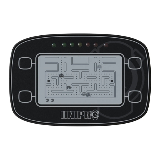
Page 46: Uniman Game
Unipro Analyser program for this. When the game is started, you can use the buttons shown on the intro screen to control UNIMAN GAME the game. -
Page 47: Info Gps
2.0 meter during a test of 24 hours. MANUFACTURE DATE This is the date this UniGo was manufactured at the Unipro production. It is a good indica- tion on how old the Laptimer is. TOTAL LAPS UniGo counts all the laps driven. This number... -
Page 48: Info Sensors
R e f e r e n c e Operating UniGo G u i d e information to the GPS system. If you see DGPS At the top status line HDOP and VDOP is + 3D it cannot get any better. shown. -
Page 49: Learn Track
( ). cable like any other USB flash drives. This will prevent the flash from being corrupted. The Unipro Analyser program do have an eject button to make this easy. FIRMWARE UPDATE Updating the firmware is very easy on UniGo. - Page 50 R e f e r e n c e Operating UniGo G u i d e Update screen when new firmware is being programmed into the flash. The next time you turn it on, you should see the new firmware version displayed on the startup screen.
-
Page 51: Troubleshooting
If you have any problems, either with the setup or with daily use, please check the following pages for suggested solutions. If you don’t find the answer to the problem here, please contact your Unipro dealer for further assistance. Weak and hard to read text splitter The contrast is set too low. -
Page 52: Cleaning
Maintenance M a i n t e n a n c e Cleaning charge for storage is between 40 and 60%. To clean the case, display, and buttons It is also a good idea to dismount the UniGo The exterior surfaces of UniGo products are and store it in the supplied box at room tem- made from plastic box with a plastic overlay. -
Page 53: Service
Unipro dealer. Unipro ApS. You can always find the updated list of world- Attempted servicing by unauthorized people wide dealers on www.uniprolaptimer.com. -
Page 54: Index
Index I n d e x Acknowledgements V Quick guide 19 Contrast too low 51 Reference guide 37 Copyright V Safety II Display 38 Safety instructions II Screenshots, examples 10 Service 53 Specifications 9 Examples, screenshots 10 Table of contents III Firmware version V Troubleshooting 51 Guarantee 53... - Page 55 I n d e x...
- Page 56 Unipro ApS • Viborg Hovedvej 24 • DK-7100 Vejle • Denmark Tel: +45 7585 1182 www.uniprolaptimer.com...
Need help?
Do you have a question about the UniGo One kit 1 and is the answer not in the manual?
Questions and answers