Table of Contents
Advertisement
Quick Links
Advertisement
Table of Contents

Subscribe to Our Youtube Channel
Summary of Contents for Ventair CU24V1
- Page 1 Operation instruction Controller for air handling units CU24V1...
- Page 2 Software version from 6.2 Contact: VentiAir s.r.o. Adolfovice 512 790 01 Bělá pod Pradědem CZ – Czech Republic IČ: 06935320 DIČ: CZ06935320 Email: obchod@ventiair.com; technical@ventiair.com Phone: +420 602 500 287 The device is manufactured in accordance with the European standard EN1886, EN13053 This documentation must always be handed over to the customer! In case of non-compliance with the conditions stated in this documentation, VentiAir s.r.o.
-
Page 3: Table Of Contents
ONTENTS Contents ............................3 Controller ............................5 Application ..........................5 Functions ..........................5 Basic parameters ........................6 Standard controller inputs and outputs ................... 6 Wiring diagram of the controller...................... 8 Controller parameters ........................9 Unit equipment ........................9 4.1.1 Selecting the type of heating and cooling ............... 9 4.1.2 Control type ........................ - Page 4 MODBUS ............................20 CU24V controller - LIST OF REGISTERS WITH ADDRESS (Function 03, 06) ......20 6.1.1 Setting the slave address of the controller ..............20 6.1.2 List of adress ........................20 Operating state register description ..................22 6.2.1 Register 1 ........................22 6.2.2 Register 2 ........................
-
Page 5: Controller
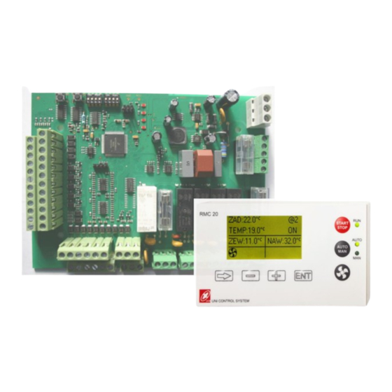
ONTROLLER 2.1 A PPLICATION The controller is dedicated for inlet-outlet AHU with exchanger or without. The controller is delivered with a remote panel RMC20 with built-in graphic display. 2.2 F UNCTIONS Temperature control Cascade control with min/max limit on supply air Supply air temperature control Water and electric heating control Water cooling and compressor control... -
Page 6: Basic Parameters
2.3 B ASIC PARAMETERS Type Characteristic Resistive PT1000 type, range -25 … +70 °C Inputs Analog 0-10V Digital Free potential contact Analog 0-10V / 2mA Outputs Modulated 21V ±2VDC / 50mA Relay 250VAC, 3A / Resistive load RS485 serial port: 2 ports Communication Distance: up to 50m Communication protocol MODBUS... - Page 7 Analog inputs (0-10VDC signal inputs) Sensor CO (optional) Temperature sensor PT1000 Exhaust Supply Exhaust behind the recuperator Outdoor Digital outputs Heating water pump Relay (230VAC) U1/U2 Electric heater Relay (230VAC) Inlet/outlet flap Relay (24VAC) Supply fan Relay Exhaust fan Relay Cooling water pump / Cooling water source operation signal Relay 1st cooling source / Condensing unit operation signal...
-
Page 8: Wiring Diagram Of The Controller
IRING DIAGRAM OF THE CONTROLLER... -
Page 9: Controller Parameters
No heater Outputs Y3 and P2 of the CU24V1 controller work independently of the type of heater, while the E1 input, depending on the type of heater, functions as an anti-freeze alarm or a high temperature alarm.. CU24V1 outputs... -
Page 10: Control Type
DAMPER: Recirculation (mixing chamber) with 0-10V control at Y6 output of the controller • EXC+DAMPER: Plate heat exchanger with by-pass or rotary heat exchanger + recirculation (mixing chamber). 0-10V control outputs of the CU24V1 controller are respectively Y5 for the exchanger and Y6 for the mixing chamber. Type of exchanger protection •... -
Page 11: Parameter Values
Below is a description of the outputs in the table. Operating Outputs CU24V1 mode Heating 0-10V: 5-10V: Unit start Operating mode select Heating control Heating control Open: heating Cooling 0-10V: 5-0V: Unit start Operating mode select Cooling control Cooling control Closed: cooling 4.2 P... -
Page 12: Cooling Parameters
Heating enabled Hysteresis HDIS-1 HDIS Outdoor temperature Enable heating Disable heating 4.2.3 OOLING PARAMETERS Name Default value Range Description PBAND 30.0°C 0 ÷ 999.9°C Proportional band. Setting PBAND = 0 means ON / OFF operation with hysteresis and the entered HYS parameter. -
Page 13: Heating - Cooling Hysteresis
4.2.4 – EATING COOLING HYSTERESIS Switching from heating to cooling takes place after the heating is switched off and the temperature rises by HYS1 above the set temperature. Switching from cooling mode to heating mode takes place after cooling is switched off and the temperature drops by HYS1 below the set temperature. Name Default value Range... -
Page 14: Heat Exchanger Parameters
4.2.7 EAT EXCHANGER PARAMETERS The ELIM parameter specifies the minimum allowed temperature on the heat exchanger outlet. When the temperature is below this threshold, the heat exchanger alarm is switched on, the air supply fan is switched off and the system starts the heat exchanger defrosting cycle. Default Name Range... -
Page 15: Recirculation Dampers Control (Mixing Chamber)
4.2.9 ECIRCULATION DAMPERS CONTROL MIXING CHAMBER After setting the type of recovery (MENU page #10), you can define at page #23 the damper control by setting the parameter DAMP: • Auto – damper control as a function of outdoor temperature according to the curve defined at MENU pages #24 and #25 •... -
Page 16: Co 2 Control
The CU24V1 controller has the ability to control CO2. The CO2 control is performed automatically after the CO2 detector has been detected in the X1 input of CU24V1. CO2 regulation is achieved either by adjusting the fan speed or by adjusting the dampers. If the damper parameter is set DAMP = AUTO, the damper is adjusted. - Page 17 Mode Function The user is denied access, at input E4 is no signal The supply fan is at maximum speed The exhaust fan is at maximum speed The supply fan runs at first speed The exhaust fan is at maximum speed The supply fan is off The exhaust fan is at maximum speed The supply fan is at minimum speed...
-
Page 18: Ethernet
THERNET uManager 10 is a converter with built-in http server, which enables remote management of air handling units controlled by Uni Control System controllers by mean of a smartphone, tablet or computer. Communication with the is done via a website with a graphic interface, so you can manage the unit from anywhere in the world if the network is available. -
Page 19: Converter Connection
UCS controller must be set. The communication parameters must be identical to those set on the UCS controller. For the ERC20 and CU24V1 controllers, you can find the communication parameters in the RMC20 panel menu. For UCS controllers, the parameters can be found in the controller menu. - Page 20 6 MODBUS 6.1 CU24V - LIST OF REGISTERS WITH ADDRESS (F 03, 06) CONTROLLER UNCTION • Protocol: MODBUS RTU (See information on the RMC20 display) • Baud rate: 9600 • Bit number: • Parity: • Stop bit: • Slave address: 6.1.1 ETTING THE SLAVE ADDRESS OF THE CONTROLLER Address...
- Page 21 ……. dot should be placed artificially Ex.: Reading the value 257 should be treated as 25.7% 2. The value 0x8000 means, the parameter is not available. 0 –………………..……………………………………………….. 65280 Alarms register bit alignment 1 – R1H: current alarm - High register ……………………….. 65281 Read and write 2 –...
- Page 22 6.2 O PERATING STATE REGISTER DESCRIPTION 6.2.1 EGISTER Bit nr Process Availability Delay at start of the unit Delay at stop of the unit Device state: 0 - system stopped by the operator 1 - system stopped by the ECO mode function 8 - 10 2 - system stopped by schedule 5 - System running...
- Page 23 6.3 A R1H, R1L LARM REGISTER DESCRIPTION 6.3.1 RH - R 1 (M EGISTER OST SIGNIFICANT HIGH REGISTER Nr bit Alarm Symbol Availability Sensor break alarm Compressor low pressure Compressor high pressure 7..15 6.3.2 RL - R 2 (L EGISTER EAST SIGNIFICANT LOW REGISTER Nr bit...
- Page 24 Outputs U1-U2 Supply fan Exhaust fan Function Heating coil Compressor Compressor Dampers inverter inverter pump 1-level 2-level start start Address 6.6 D ISCRET INPUTS IGITAL INPUTS FUNCTION Inputs Frost thermostat or Compressor Function high temperature Filter guard Fan alarm System start alarm thermostat Address...
Need help?
Do you have a question about the CU24V1 and is the answer not in the manual?
Questions and answers