Advertisement
Available languages
Available languages
Quick Links
Download this manual
See also:
Use and Care Manual
IMPORTANT - PLEASE KEEP FOR THE USE OF THE LOCAL ELECTRICAL INSPECTOR
INSTALLATION INSTRUCTIONS
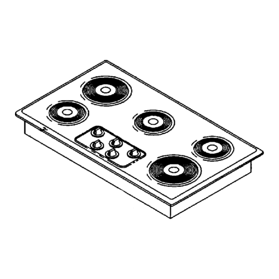
Electric Counter Mounted Surface Units
READ "SAFETY INSTRUCTIONS" IN USE & CARE BOOK BEFORE USING UNIT
In order to assure the best results in service, proper operation and maximum efficiency, the original installation and adjustment
should be made by your dealer, his authorized agent, or by your local utility company before you attempt to operate the surface
unit.
LOCATION
Place unit where it will be well lighted. For proper cooking results, it must be level. THESE ELECTRIC COUNTER MOUNTED
SURFACE UNITS ARE APPROVED FOR INSTALLATION IN COMBUSTIBLE CABINETRY. SEE INSTALLATION
DIAGRAM FOR THE APPROPRIATE UNIT ON THE FOLLOWING PAGES OF THIS INSTRUCTION SHEET.
OUTSIDE WIRING
Your local utility company will tell you whether the present
electric service to your home is adequate. It may be
necessary to increase the size of the wiring to the house and
service switch to take care of the electrical load demanded
by the surface unit and/or oven. The wattage (K.W. rating)
load for the range is specified on the name plate on the unit.
HOUSE WIRING
Most local building regulations and codes require that all
electrical wiring be done by licensed electricians. All wiring
should conform to Local and National Electrical Codes. This
unit requires a single phase three wire 120/240 or a 120/208
volt, 60 Hz, AC circuit. Wiring codes require that a separate
circuit be run from the main entrance panel to the unit and
that it be equipped with separate disconnect switch and
fuses, either in the main entrance panel or in a separate
switch and fuse box.
UNIT CONNECTIONS
This unit is supplied with a 240/208 volt wiring system
consisting of 2 insulated conductors and 1 bare grounding
wire for use on a 3 wire 120/240 or a 120/208 volts, 60 Hz,
AC branch circuit. The flexible armored conduit supplied
with the unit must be connected to an approved electrical
junction box by means of an approved conduit to box
connector.
THE BARE WIRE IN THE UNIT CONDUIT IS CONNECTED
TO THE FRAME OF THE UNIT. THE FRAME OF THE UNIT
IS GROUNDED TO NEUTRAL OF THE BRANCH CIRCUIT
ONLY WHEN THIS BARE WIRE IS CONNECTED TO THE
NEUTRAL (WHITE) WIRE OF THE BRANCH CIRCUIT. If
used on new branch-circuit installations (1996 NEC), mobile
homes, recreational vehicles, or in an area where local
codes prohibit grounding through the neutral conductor, the
bare wire at the end of the unit conduit must be used to
ground the unit in accordance with local code. The red and
black wires must be connected to two conductors (red and
black) of the branch circuit. The neutral (white) wire of the
branch circuit must be properly insulated. Connect all wires
to the branch circuit with approved connectors. Use copper
or aluminum wire. If aluminum wire is used, use connectors
recognized for joining aluminum to copper.
APPROVED
CONNECTOR
BLACK
APPROVED
BOX
L1
NEUTRAL
RANGE GROUNDED THROUGH NEUTRAL CONDUCTOR
APPROVED
CONNECTOR
BLACK
INSULATED
L1
NEUTRAL
WIRING METHOD IF CODE DOES NOT PERMIT GROUNDING
THROUGH NEUTRAL CONDUCTOR & ALSO REQUIRED IN MOBILE
HOMES.
WARNING:
Be sure UNIT is DISCONNECTED from
POWER SUPPLY before examining any of the electrical
equipment.
RANGE CONDUIT
RED
BARE
APPROVED INSULATED
CONNECTIONS
L2
BRANCH CIRCUIT
(POWER SUPPLY)
RANGE CONDUIT
RED
BARE
APPROVED BOX
APPROVED INSULATED
CONNECTIONS
L2
BRANCH CIRCUIT
(POWER SUPPLY)
SEPARATE GROUND
8101P408-60
(05-02-01)
Advertisement

Related Manuals for Maytag MEC4430AA


Summary of Contents for Maytag MEC4430AA
-
Page 1: Installation Instructions
The wattage (K.W. rating) load for the range is specified on the name plate on the unit. HOUSE WIRING Most local building regulations and codes require that all electrical wiring be done by licensed electricians. - Page 2 If cabinet storage is to be provided, the hazard can be reduced by installing a range hood that projects horizontally a minimum of 5-inches beyond the bottom of the cabinets.”...
- Page 3 36² Cooktop with Coil Elements FIGURE 2 30² Smoothtop Ceramic Cooktop FIGURE 3 3/8² FLEXIBLE CABLE 48² LONG FURNISHED AND INSTALLED BY MANUFACTURER (CONNECT TO 240/120 VOLT ELECTRICAL SERVICE)
-
Page 4: Instrucciones De Instalación
IMPORTANTE — CONSERVE ESTOS MATERIALES PARA USO DEL INSPECTOR ELÉCTRICO LOCAL INSTRUCCIONES DE INSTALACIÓN Unidades eléctricas de superficie montadas en LEA LAS “INSTRUCCIONES DE SEGURIDAD” EN EL MANUAL DE CUIDADO Y USO ANTES DE USAR LA UNIDAD Para garantizar los mejores resultados en el servicio, el funcionamiento apropiado y la máxima eficiencia, la instalación y el ajuste originales debe realizarlos el distribuidor, su agente autorizado o la compañía de servicios públicos locales antes de que intente operar la unidad de superficie. - Page 5 Las unidades mostradas en las figuras 1 y 2 pueden instalarse en mostradores combustibles y deben estar espaciadas cuando menos a (1² de) los lados y la parte posterior combustible encima del mostrador. La unidad mostrada en la figura 3 puede instalarse en mostradores combustibles y adyacentes a (0²...
- Page 6 Superficie para cocinar con elementos de espiral de 36² ² ² ² FRENTE DE LA UNIDAD 3 3/8² MÍNIMAS MÁS EL ESPACIO LIBRE ADENTRO PARA OBTENER EL ÁNGULO CORRECTO DEL CONDUCTOR Y DEL ALAMBRE. Superficie para cocinar lisa de cerámica de 30 ² ² ² ² 2 3/4²...
-
Page 7: Mise En Service
IMPORTANT - CONSERVER À L’USAGE DE L’INSPECTEUR EN ÉLECTRICITÉ LOCAL MISE EN SERVICE Plaques de cuisson électriques montés sur un comptoir LIRE LES “MESURES DE SÉCURITÉ” DANS LE MANUEL DE L’UTILISATEUR AVANT Pour assurer un fonctionnement correct et efficient et des résultats optimums au niveau du service après-vente, la pose et le réglage initiaux doivent être réalisés par le revendeur, son prestataire agréé... - Page 8 Les plaques de cuisson des figures 1 et 2 peuvent être posées dans un comptoir en matériau combustible et doivent être placées à au moins 1 po de parois en matériau combustible au-dessus de la surface de cuisson, à l’arrière et sur les côtés. La plaque de cuisson de la figures 3 peut être posée dans un comptoir en matériau combustible où...
- Page 9 Plaque de cuisson de 91,4 cm avec éléments tubulaires DEVANT DE LA PLAQUE 50,2 CM MIN. 6,7 CM MIN. 88,6 CM MIN. Plaque de cuisson en vitrocéramique de 76,2 cm 53,3 CM MIN. 7 CM MIN. DEVANT DE LA PLAQUE 74,8 CM MIN.
Need help?
Do you have a question about the MEC4430AA and is the answer not in the manual?
Questions and answers