Table of Contents
Advertisement
Advertisement
Table of Contents

Subscribe to Our Youtube Channel
Related Manuals for Powersmart PS55


Summary of Contents for Powersmart PS55
- Page 1 INSTRUCTION MANUAL 1500W Inverter Generator Model # PS55 Have product questions or need technical support? Please scan the QR code to enter our official website and contact us! Website:www.powersmartusa.com Toll free: 1-800-791-9458 M-F 9-5 EST Website Email: support@amerisuninc.com...
-
Page 3: Table Of Contents
Stopping the generator…………………………………………………... Maintenance……………………………………………………………... Storage & transport procedures…………………………………………. Troubleshooting…………………………………………………………. Wiring diagram…………………………………………………………. Exploded view & parts list……………………………………………… Warranty statement……………………………………………………… TECHNICAL DATA 1500W Inverter Generator Model#PS55 Engine type: 4 stroke, OHV, single cylinder with forced air-cooling system Start type: Manual Phase: Single Rated wattage:... -
Page 4: Introduction
Thank You for Purchasing a PowerSmart® Product. This manual provides information regarding the safe operation and maintenance of this product. Every effort has been made to ensure the accuracy of the information in this manual. PowerSmart® reserves the right to change this product and specifications at any time without prior notice. -
Page 5: General Safety Rules
GENERAL SAFETY RULES For any questions regarding the hazard and safety notices listed in this manual or on the product, please call (800) 791-9458, Mon-Fri 9-5 EST before using the generator. Please read and understand the instructions in this manual before starting the engine or attempting to operate this unit. DANGER: CARBON MONOXIDE Using a generator indoors CAN KILL YOU IN MINUTES. -
Page 6: Important Safety Instructions
Turn the engine switch to “OFF” position when the engine is not running. IMPORTANT SAFETY INSTRUCTIONS SAVE THESE INSTRUCTIONS – This manual contains important instructions for the PowerSmart® 1500W generator that should be followed during installation and maintenance of the generator. -
Page 7: Symbols
SYMBOLS Some of the following symbols may be used on this product. Please study them and learn their meaning. Proper interpretation of these symbols will allow you to operate the product better and safer. SYMBOL NAME DESIGNATION/EXPLANATION Volts Voltage Amperes Current Hertz Frequency (cycles per second) -
Page 8: Knowing Your Generator
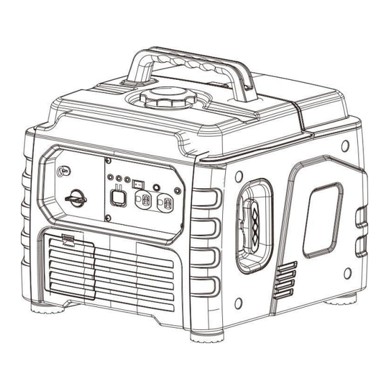
KNOWING YOUR GENRATOR Use the illustrations below to become familiar with the locations and functions of the various components and controls of this generator Control Panel... - Page 9 Oil warning light (red) When the oil level falls below the lower level, the oil warning light comes on and then the engine stops automatically. Unless you refill with oil, the engine will not start again. Tip: If the engine stalls or does not start, turn the engine switch to "ON" and then pull the recoil starter. If the oil warning light flickers for a few seconds, the engine oil is insufficient.
- Page 10 Reset button The reset button is used to restore output if an overload occurs. To restore output, reduce the loads and press the rest button. AC reset Grounding terminal The grounding terminal is designed to prevent electric shock by connecting it to the grounding wire. The generating set must be properly grounded before operation.
-
Page 11: Generator Preparation
GENERATOR PREPARATION The following section describes steps necessary to prepare the generator for use. If after reading this section, you are unsure about how to perform any of the steps please call (800) 791-9458 Mon-Fri 9-5 EST for customer service. Failure to perform these steps properly can damage the generator or shorten its lifespan. Unpacking Unpack the generator and all its parts. - Page 12 3. Operating Condition Check for loose or damaged parts, signs of oil or fuel leaks, and any other condition that may affect proper operation. Repair or replace all damaged or defective parts immediately. WARNING: Failing to correct problem(s) before operation could result in property damage, serious injury or DEATH.
- Page 13 Install dipstick into hole, rest on oil fill neck, DO NOT thread cap into hole. Fill the specified amount of the recommended engine oil, and then install and tighten the oil filler cap. Dipstick Install the cover and tighten the screws. CAUTION: Operate generator only on a level surfaces.
- Page 14 CATION: Never use engine or carburetor cleaner products in the fuel tank or permanent damage may occur. It is important to prevent gum deposits from forming in essential fuel system parts, such as the carburetor, fuel filter, fuel hose or tank during storage. Also, experience indicates that ...
-
Page 15: Starting The Generator
STARTING THE GENERATOR CAUTION: Disconnect all electrical loads from the generator before attempting to start. Pull the starter handle 6-8 times to prefill fuel system before initial operation or removal from long term storage. Failure to do so could result in bad starting experience. 1. -
Page 16: Using The Generator
USING THE GENERATOR WARNING: It is prohibited to start or close the generating set when the output terminal of generating set is connected to an electric device is in “ON” state. CONNECT TO ELECTRICAL DEVICES 1. Inspect power cord for damage before using. There is a hazard of electrical shock from crushing, cutting or heat damage. -
Page 17: Stopping The Generator
WARNING: It is necessary to equip with circuit protector or switch to isolate the generating set from the electric utility when the generating set is mainly used for backup. Failure to isolate the generating set from the power utility may result in injury or death to electric utility workers and damage to the generating set due to back feed of electrical energy. - Page 18 MAINTENANCE SCHEDULE Stop the generating set before serving, disconnect all electric devices and battery (If equipped),and cool down the generating set completely. Serve the generating set in a clean, dry and flat area, so that no accident would happen during the serving. Please make the wheel in brake state to stop accidental movement of generating set.
- Page 19 GENERATING SET MAINTENANCE WARNING: Never clean the generator when it is running! Never use water to clean the generating set. Water can enter the generating set through the cooling slots and damage the generating set windings. WARNING: Do not modify the generator in any way. Do not tamper with governed speed. Generator supplies correct rated frequency and voltage when running at factory set.
- Page 20 SPARK PLUG Spark plug gap : 0.6mm-0.8mm(0.024-0.031 in). Spark plug tighten torque: 12.5N.m The spark plug is important for proper engine operation. A good spark plug should be intact, free of deposits, and properly gapped. Refer to Recommended Maintenance Schedule. To inspect the spark plug: 1.
- Page 21 STORAGE & TRANSPORT PROCEDURES STORAGE WARNING: Gasoline is highly flammable and extremely explosive. Empty the fuel tank and shut off fuel valve before storing or transporting this generating set. The generating set should be started at least once every 2 weeks and allowed to run for at least 20 minutes.
- Page 22 TROUBLESHOOTING ENGINE WON’T START...
- Page 23 WIRING DIAGRAM...
- Page 24 EXPLODED VIEW & PARTS LIST...
- Page 25 PS55-020 CRANKCASE SUBASSEMBLY. PS55-021 DEEP GROOVE BALL BEARING PS55-022 CRANKSHAFT ASSY. PS55-023 GEAR, TIMING DRIVE PS55-024 DEEP GROOVE BALL BEARING PS55-025 POSITION PIN - TYPE A PS55-026 COVER, CRANKCASE PS55-027 BOLT PS55-028 TUBE, BREATHER PS55-029 SHAFT, VALVE ROCKER PS55-030 LIFTER SUBASSEMBLY, VALVE...
- Page 26 PS55-048 CARBURETOR ASSY. PS55-049 STRAINER , FUEL PS55-050 AIR CLEANER SEAL GASKET PS55-051 AIR CLEANER INTAKE DUCT ASSEMBLY PS55-052 HEXAGON NUT WITH FLANGE PS55-053 CLIP, GOVERNOR ROD PS55-054 SENSOR, ENGINE OIL PS55-055 COIL, IGNITION PS55-056 BOLT PS55-057 BOLT PS55-058 DIPSTICK SUBASSEMBLY, OIL...
- Page 27 PS55-099 BOLT PS55-100 COLLAR PS55-101 PLUG, END PS55-102 CROSS-RECESSED PAN HEAD SCREW PS55-103 REGULATOR, VOLTAGE PS55-104 SOCKET SUBASSEMBLY, POWER SUPPLY...
- Page 28 Limited Warranty, you must return the entire power tool product; transportation prepaid, to PowerSmart Include a legible copy of the original receipt, which lists the date of purchase (month and year) and the name of the company purchased from.
Need help?
Do you have a question about the PS55 and is the answer not in the manual?
Questions and answers
Do I need 2 cycle oil
No, you do not need 2 cycle oil for the Powersmart PS55. It uses 4-stroke engine oil, specifically SAE 10W-30 that meets SJ, SL, or equivalent API standards.
This answer is automatically generated