
Related Manuals for TLV EF200R-C


Summary of Contents for TLV EF200R-C
- Page 1 172-65760M-01 (EF200R-C Vortex flowmeter) 7 June 2022 Vortex flowmeter EF200R-C Copyright © 2022 by TLV CO., LTD. All rights reserved...
-
Page 2: Table Of Contents
EF200R-C Table of contents Process About this document Medium temperature range Symbols Pressure-temperature ratings Nominal pressure of sensor Function and system design Pressure specifications Measuring principle Pressure loss Measuring system Thermal insulation Input Mechanical construction Measured variable Dimensions in SI units Measuring range Dimensions in US units Operable flow range Weight Materials Flange connections Output Output signal Operability Signal on alarm Operating concept Load Languages Low flow cut off Local operation Galvanic isolation Remote operation Protocol-specific data Power supply Certificates and approvals Terminal assignment CE mark Supply voltage... -
Page 3: About This Document
EF200R-C About this document Symbol Meaning Direct current Alternating current Direct current and alternating current Ground connection A grounded terminal which, as far as the operator is concerned, is grounded via a grounding system. Protective Earth (PE) A terminal which must be connected to ground prior to establishing any other connections. The ground terminals are situated inside and outside the device: • Inner ground terminal: Connects the protectiv earth to the mains supply. • Outer ground terminal: Connects the device to the plant grounding system. Symbols for certain types of information Symbol Meaning Permitted Procedures, processes or actions that are permitted. Preferred Procedures, processes or actions that are preferred. Forbidden Procedures, processes or actions that are forbidden. Indicates additional information. Reference to documentation. Reference to page. Reference to graphic. Visual inspection. Symbols in graphics... -
Page 4: Function And System Design
EF200R-C Function and system design Measuring principle Vortex meters work on the principle of the Karman vortex street . When fluid flows past a bluff body, vortices are alternately formed on both sides with opposite directions of rotation. These vortices each generate a local low pressure. The pressure fluctuations are recorded by the sensor and converted to electrical pulses. The vortices develop very regularly within the permitted application limits of the device. Therefore, the frequency of vortex shedding is proportional to the volume flow. A0033465 Sample graphic The calibration factor (K-factor) is used as the proportional constant: Pulses K-Factor = Unit Volume [m³] Within the application limits of the device, the K-factor only depends on the geometry of the device. It is for Re > 10 000: • Independent of the flow velocity and the fluid properties viscosity and density • Independent of the type of substance under measurement: steam, gas or liquid The primary measuring signal is linear to the flow. After production, the K-factor is determined in the factory by means of calibration. It is not subject to long-time drift or zero-point drift. The device does not contain any moving parts and does not require any maintenance. The capacitance sensor The sensor of a vortex flowmeter has a major influence on the performance, robustness and reliability of the entire measuring system. The robust DSC sensor is: • burst-tested • tested against vibrations • tested against thermal shock (thermal shocks of 150 K/s) The measuring device uses the tried-and-tested, capacitance measuring technology,... - Page 5 EF200R-C Temperature measurement The measuring device can also measure the temperature of the medium. The temperature is measured via Pt 1000 temperature sensors. These are located in the paddle of the DSC sensor and are therefore in the direct vicinity of the fluid. A0034068 DSC sensor Pressure and temperature measurement The measuring device can also measure the pressure and temperature of the fluid. The temperature is measured via Pt 1000 temperature sensors. These are located in the paddle of the DSC sensor and are therefore in the direct vicinity of the fluid. Pressure measurement is located directly on the meter body at the level of the bluff body. The position of the pressure tapping was chosen so that pressure and temperature could be measured at the same point. This enables accurate density and/or energy compensation of the fluid using pressure and temperature. The measured pressure tends to be somewhat lower than the line pressure. For this reason, TLV offers a correction to the line pressure (integrated in the device). Order code for "Sensor version; DSC sensor; measuring tube": • Option "Mass steam; 316L; 316L (integrated pressure/temperature measurement)" Lifelong calibration Experience has shown that recalibrated measuring devices demonstrate a very high degree of stability compared to their original calibration: The recalibration values were all within the original measuring accuracy specifications of the devices. This applies to the measured volume flow, the device's primary measured variable. Various tests and simulation have shown that once the radii of the edges on the bluff body are less than 1 mm (0.04 in), the resulting effect does not have a negative impact on accuracy. If the radii of the edges on the bluff body do not exceed 1 mm (0.04 in), the following general statements apply (in the case of non-abrasive and non-corrosive media, such as in most water and steam applications): • The measuring device does not display an offset in the calibration and the accuracy is still guaranteed. • All the edges on the bluff body have a radius that is typically smaller in size. As the measuring devices are naturally also calibrated with these radii, the measuring device remains within the specified accuracy rating provided that the additional radius that is produced as a result of wear and tear does not exceed 1 mm (0.04 in). Consequently, it can be said that the product line offers lifelong calibration if the measuring device is used in non-abrasive and non-corrosive media.
- Page 6 EF200R-C Sensors with integrated nominal diameter reduction In many applications the nominal diameter of the customer's pipe does not match the nominal diameter that is optimum for a vortex meter. As a result, the flow velocity is too low for vortex formation after the bluff body. This is expressed in signal loss in the lower flow range. The flow velocity can be increased by reducing the nominal diameter by one sizes. This enables the installation of the following adapters: A0034060 A0019070 Nominal diameter reduction by installing various adapters and pipe segments in the pipe Nominal diameter reduction by using the Prowirl with integrated line size reduction Reducer element Straight pipe segment as the inlet run (min. 15 × DN) upstream from the vortex meter Straight pipe segment as the outlet run (min. 5 × DN) downstream from the vortex meter Expansion element • EF200R-C ": with single inner diameter line size reduction, e.g. from DN 80 (3") to DN 50 (2") These models offer the following benefits: Savings in terms of cost and time: the additional adapters are replaced entirely by one single device • Measuring range extended for lower flow rates • Lower risk in the planning phase as same lengths are used compared to standard flanged devices • All device types can be used alternatively without the need for complicated changes to the layout • Accuracy specifications identical to those for standard devices Inlet and outlet runs to be considered → See page 31. o.r. = of reading...
-
Page 7: Measuring System
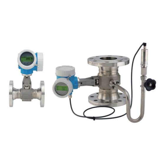
EF200R-C Measuring system The device consists of a transmitter and a sensor. Two device versions are available: • Compact version ‒ transmitter and sensor form a mechanical unit. • Remote version - transmitter and sensor are mounted in separate locations. Transmitter EF200-C Device versions and materials: • Compact or remote version, aluminum coated: Aluminum, AlSi10Mg, coated Configuration: • Via four-line local display with key operation or via four-line, • Via operating tools A0013471 Sensor EF200R-C Flanged version with integrated nominal diameter reduction: • Two versions with a different nominal diameter range are available: • "R-type" with single inner diameter line size reduction: DN 25R to 200R (1R to 8R") • Materials: • Measuring tubes DN 15 to 150 (½ to 6"): stainless cast steel, CF3M/ 1.4408 A0034075 Pressure measuring cell Versions: Pressure components • Pressure measuring cell 40 bar̲a Material •... -
Page 8: Input
EF200R-C Input Measured variable Direct measured variables Description Measured variable Mass; 316L; 316L (integrated temperature measurement) • Volume flow • Temperature Calculated measured variables Version with pressure measuring cell Description Measured variable Mass; 316L; 316L (integrated temperature measurement) • Corrected volume flow • Mass flow • Calculated saturated steam pressure • Energy flow • Heat flow difference • Specific volume Measuring range The measuring range is dependent on the nominal diameter, the fluid and environmental influences. The following specified values are the largest possible flow measuring ranges (Q to Q ) for each nominal diameter. Depending on the fluid properties and environmental influences, the measuring range may be subject to additional restrictions. Additional restrictions apply to both the lower range value and the upper range value. Flow measuring ranges in SI units Liquids... - Page 9 EF200R-C Flow measuring ranges in US units Liquids Gas/steam [in] [ft³/min] [ft³/min] 0.061 to 2.9 0.31 to 15 1½R 0.19 to 8.8 0.93 to 74 0.46 to 22 2.3 to 180 0.77 to 36 3.8 to 480 1.7 to 81 8.6 to 1 3 to 140 15 to 1 6.8 to 320 34 to 4 Flow velocity A0033468 Internal diameter of measuring tube (corresponds to dimension K→ See page 41) Velocity in measuring tube Flow The internal diameter of measuring tube D is denoted in the dimensions as dimension K.→ See page 25. Calculation of flow velocity: · 4 Q [ ...
- Page 10 EF200R-C Lower range value A restriction applies to the lower range value due to the turbulent flow profile, which only occurs with Reynolds numbers greater than 5000. The Reynolds number is dimensionless and indicates the ratio of the inertia force of a fluid to its viscous force when flowing and is used as a characteristic variable for pipe flows. In the case of pipe flows with Reynolds numbers less than 5000, periodic vortices are no longer generated and flow rate measurement is no longer possible. The Reynolds number is calculated as follows: 4 · Q [m³/s] · [kg/m³] ρ π · D [m] · µ [Pa · s] 4 · Q [ft³/s] · [lbm/ft³] ρ π · D [ft] · µ [lbf · s/ft ] ² A0034291 Reynolds number Flow Internal diameter of measuring tube (corresponds to dimension K→ See 41) µ Dynamic viscosity ρ Density The Reynolds number, 5 000 together with the density and viscosity of the fluid and the nominal diameter, is used to calculate the corresponding flow rate. 5000 · · D [m] ·...
- Page 11 EF200R-C The lowest flow velocity that can be measured on account of the signal amplitude v is derived AmpMin from the S ensitivity parameter and the steam quality (x) or from the force of vibrations present (a). 1 ³ mf [m/s] [m/s] = max · AmpMin x² ρ ³ · AmpMin ρ x² A0034303 Minimum measurable flow velocity based on signal amplitude AmpMin Sensitivity Steam quality ρ Density [m/s] · · D [m] π ² AmpMin [m /h] = ³ · 3600 [s/h] AmpMin ρ...
- Page 12 EF200R-C Upper range value The measuring signal amplitude must be below a certain limit value to ensure that the signals can be evaluated without error. This results in a maximum permitted flow rate Q AmpMax 350 [m/s] · · D [m] π ² [m /h] = ³ · 3600 [s/h] AmpMax ρ ³] 4 · 1 ³] 1148 [ /s] · · D [ft] π ² [ /min] = ³ · 60 [s/min] AmpMax 4 ·...
-
Page 13: Operable Flow Range
EF200R-C The effective upper range value Q is determined using the smallest of the three values Q High and Q AmpMax Ma=0.3 [m /h] ³ [m /h] ³ [m /h] = min ³ AmpMax High [m /h] ³ Ma = 0.3 [ /min] [ /min] ³ AmpMax High [ /min] Ma = 0.3 A0034338 Effective upper range value High Maximum measurable flow rate Maximum measurable flow rate based on signal amplitude AmpMax Restricted upper range value is dependent on Mach number Ma = 0.3 For liquids, the occurrence of cavitation may also restrict the upper range value. - Page 14 EF200R-C Pulse/frequency/switch output Function Can be set to pulse, frequency or switch output Version Passive, open collector Maximum input values • DC 35 V • 50 mA Voltage drop • For 2 mA: 2 V • For 10 mA: 8 V Residual current 0.05 mA Pulse output Pulse width Adjustable: 5 to 2000 ms Maximum pulse rate 100 Impulse/s Pulse value Adjustable Assignable measured • Mass flow variables • Volume flow • Corrected volume flow • Total mass flow • Energy flow • Heat flow difference Frequency output...
-
Page 15: Signal On Alarm
EF200R-C Signal on alarm Depending on the interface, failure information is displayed as follows: Current output 4 to 20 mA 4 to 20 mA Failure mode Choose from: • 4 to 20 mA in accordance with NAMUR recommendation NE 43 • 4 to 20 mA in accordance with US • Min. value: 3.59 mA • Max. value: 22.5 mA • Freely definable value between: 3.59 to 22.5 mA • Actual value • Last valid value Pulse/frequency/switch output Pulse output Failure mode No pulses Frequency output Failure mode Choose from: • Actual value • 0 Hz • Defined value: 0 to 1 250 Hz Switch output Failure mode Choose from:... -
Page 16: Load
EF200R-C Load Load for current output: 0 to 500 Ω, depending on the external supply voltage of the power supply unit Calculation of the maximum load Depending on the supply voltage of the power supply unit (U ), the maximum load (R ) including line resistance must be observed to ensure adequate terminal voltage at the device. In doing so, observe the minimum terminal voltage • For U = 17.9 to 18.9 V: R (U - 17.9 V): 0.0036 A B • For U = 18.9 to 24 V: R (U - 13 V): 0.022 A B • For U = 24 V: R 500 Ω B [Ω] U [V] A0013563 Operating range Sample calculation Supply voltage of power supply unit: U =19 V Maximum load: R (19 V - 13 V): 0.022 A = 273 Ω B Low flow cut off The switch points for low flow cut off are preset and can be configured. -
Page 17: Power Supply
EF200R-C Power supply Terminal assignment Transmitter Connection versions ‒ ‒ A0033475 Maximum number of terminals Terminals 1 to 4: Without integrated overvoltage protection Output 1 (passive): supply voltage and signal transmission Output 2 (passive): supply voltage and signal transmission Ground terminal for cable shield Terminal numbers Output 1 Output 2 1 (+) 2 (-) 3 (+) 4 (-) 4-20 mA (passive) Pulse/frequency/switch output (passive) Output 1 must always be used; output 2 is optional. Connecting cable for remote version Transmitter and sensor connection housing In the case of the remote version, the sensor and transmitter are mounted separately from on another and connected by a connecting cable. Connection is performed via the sensor connection housing and the transmitter housing. Terminals are always used to connect the connecting cable in the sensor connection housing (tightening torques for screws for cable strain relief: 1.2 to 1.7 Nm). - Page 18 EF200R-C Connection via terminals ~20° 8 mm A0041608 Loosen the securing clamp of the transmitter housing. Turn the transmitter housing clockwise by approx. 20°. The connection board of the wall housing is connected to the electronics board of the transmitter via a signal cable! ► Pay attention to the signal cable when lifting the transmitter housing! Lift the transmitter housing, plug the signal cable out of the connection board of the wall holder and remove the transmitter housing. Release the cable gland and insert the connecting cable (use the shorter stripped end of the connecting cable). Wire the connecting cable → Fig. 2, See 19 → Fig. 3, See 19. Reverse the removal procedure to reassemble the transmitter housing. Firmly tighten the cable gland.
-
Page 19: Supply Voltage
EF200R-C Connecting cable ‒ ‒ A0033476 Terminals for connection compartment in the transmitter wall holder and the sensor connection housing Terminals for connecting cable Grounding via the cable strain relief Terminal number Assignment Cable color Connecting cable Supply voltage Brown Grounding White RS485 (+) Yellow RS485 (‒) Green Connecting cable (option "mass pressure-/temperature-compensated") Order code for "Sensor version; DSC sensor; measuring tube", option ‒ ‒ BK YE BU ‒ ‒ A0034571 Terminals for connection compartment in the transmitter wall holder and the sensor connection housing Terminals for connecting cable Grounding via the cable strain relief... -
Page 20: Power Consumption
EF200R-C Terminal number Assignment Cable color Connecting cable RS485 (-) DPC Brown RS485 (+) DPC White Reset Green Supply voltage Grounding Black RS485 (+) Yellow RS485 (‒) Blue Supply voltage Transmitter An external power supply is required for each output. Supply voltage for a compact version without a local display Order code for "Output; input" Minimum Maximum 1) terminal voltage terminal voltage 4-20 mA, pulse/frequency/switch output DC 12 V DC 35 V The minimum terminal voltage increases if local operation is used: see the following table Increase in minimum terminal voltage Increase in minimum “Display” terminal voltage LCD display + DC 1 V Local operation ... -
Page 21: Power Supply Failure
EF200R-C Power supply failure • Totalizers stop at the last value measured. • Depending on the device version, the configuration is retained in the device memoryor in the pluggable data memory (HistoROM DAT). • Error messages (incl. total operated hours) are stored. Electrical connection Connecting the transmitter A0033480 Cable entries for inputs/outputs Remote version connection Connecting cable A0033481 Connecting cable connection Wall holder with connection compartment (transmitter) Connecting cable Sensor connection housing Terminals are always used to connect the connecting cable in the sensor connection housing (tightening torques for screws for cable strain relief: 1.2 to 1.7 Nm). - Page 22 EF200R-C Connection examples Current output 4-20 mA HART 4...20 mA A0028762 Connection example for 4 to 20 mA HART current output (passive) Automation system with current input (e.g. PLC) Power supply Cable shield provided at one end. The cable shield must be grounded at both ends to comply with EMC requirements; observe cable specifications Analog display unit: observe maximum load Transmitter Pulse/frequency output 12345 A0028761 Connection example for pulse/frequency output (passive) Automation system with pulse/frequency input (e.g. PLC) Power supply Transmitter: Observe input values Switch output A0028760 Connection example for switch output (passive) Automation system with switch input (e.g. PLC) Power supply Transmitter: Observe input values...
-
Page 23: Potential Equalization
EF200R-C Potential equalization Requirements Please consider the following to ensure correct measurement: • Same electrical potential for the fluid and sensor • Remote version: same electrical potential for the sensor and transmitter • Company-internal grounding concepts • Pipe material and grounding Terminals • For device version without integrated overvoltage protection: plug-in spring terminals for wire cross-sections 0.5 to 2.5 mm (20 to 14 AWG) • For device version with integrated overvoltage protection: screw terminals for wire cross-sections 0.2 to 2.5 mm (24 to 14 AWG) Cable entries • Thread for cable entry: • For non-hazardous and hazardous areas (not for XP): G ½" Cable specification Permitted temperature range • The installation guidelines that apply in the country of installation must be observed. • The cables must be suitable for the minimum and maximum temperatures to be expected. Signal cable Current output 4 to 20 mA A shielded cable is recommended. Observe grounding concept of the plant. Pulse/frequency/switch output Standard installation cable is sufficient. -
Page 24: Overvoltage Protection
EF200R-C Connecting cable (option "mass pressure-/temperature-compensated") Order code for "Sensor version; DSC sensor; measuring tube", option Standard cable [(3 × 2) + 1] × 0.34 mm (22 AWG)PVC cable with common shield 1) (3 pairs, pair-stranded) Flame resistance According to DIN EN 60332-1-2 Oil-resistance According to DIN EN 60811-2-1 Shielding Galvanized copper-braid, opt. density approx. 85% Cable length 30 m (98 ft) Operating temperature When mounted in a fixed position: ‒50 to +105 °C (‒58 to +221 °F); when cable can move freely: ‒25 to +105 °C (‒13 to +221 °F) UV radiation may cause damage to the outer jacket of the cable. Protect the cable from exposure to sun as much as possible. Overvoltage protection The device can be ordered with integrated overvoltage protection for diverse approvals: Order code for "Accessory mounted", option NA "Overvoltage protection" 1) Input voltage range Values correspond to supply voltage specifications → See 20 Resistance per channel 2 · 0.5 Ω max. DC sparkover voltage 400 to 700 V Trip surge voltage < 800 V Capacitance at 1 MHz < 1.5 pF Nominal discharge current 10 kA (8/20 μs) Temperature range ‒40 to +85 °C (‒40 to +185 °F) -
Page 25: Maximum Measured Error
EF200R-C Maximum measured error Base accuracy o.r. = of reading A0034077 Reynolds number Reynolds number for minimum permitted volume flow in measuring tube • Standard • Option N "0.65% volume PremiumCal 5-point [m/s] · · D [m] π ² AmpMin [m /h] = ³ · 3600 [s/h] AmpMin ρ ³] 4 · 1 ³] [ /s] · · D [ft] π... - Page 26 EF200R-C Temperature • Saturated steam and liquids at room temperature, if T > 100 °C (212 °F): < 1 °C (1.8 °F) • Gas: < 1% o.r. [K] • Volume flow: 70 m/s (230 ft/s): 2 % o.r. • Rise time 50% (stirred under water, following IEC 60751): 8 s Pressure 1) 2) Order code for "Pressure component" Nominal value Pressure ranges and measured errors [bar abs.] Pressure range Maximum measured error [bar abs.] Pressure measuring cell 40 bar̲a 0.01 p 8 0.5 % of 8 p 40 8 bar abs. 0.5 % o.r. The "mass" sensor version (integrated pressure/temperature measurement) is available only for measuring devices in HART communication mode. The specific measured errors refer to the position of the measurement in the measuring tube and do not correspond to the pressure in the pipe connection line upstream or downstream from the measuring device. No measured error is specified for the measured error for the "pressure" measured variable that can be assigned to the outputs. Mass flow saturated steam Sensor version Mass (integrated temperature Mass (integrated pressure/...
- Page 27 EF200R-C Water mass flow Sensor version Mass (integrated temperature measurement) Process pressure Flow velocity Reynolds number Measured value deviation Standard [bar abs.] [m/s (ft/s)] range All pressures All velocities to Re < 0.85 % to Re < 2.7 % Order code for "Calibration flow", option N "0.65% volume PremiumCal 5-point" Mass flow (user-specific liquids) Example • Acetone is to be measured at fluid temperatures from +70 to +90 °C (+158 to +194 °F). • For this purpose, the R eference temperature parameter (7703) (here 80 °C (176 °F)), Reference density parameter (7700) (here 720.00 kg/m ) and Linear expansion coefficient parameter (7621) (here 18.0298 × 10 1/VC) must be entered in the transmitter. • The overall system uncertainty, which is less than 0.9% for the example above, is comprised of the following measurement uncertainties: uncertainty of volume flow measurement, uncertainty of temperature measurement, uncertainty of the density-temperature correlation used (including the resulting uncertainty of density). Mass flow (other media) Depends on the selected fluid and the pressure value, which is specified in the parameters. Individual error analysis must be performed.
-
Page 28: Repeatability
EF200R-C Accuracy of outputs The outputs have the following base accuracy specifications. Current output ±10 µA Accuracy Pulse/frequency output o.r. = of reading Accuracy Max. ±100 ppm o.r. Repeatability o.r. = of reading ½ · D ³ r = % o.r. A0042121-EN [% o.r.] 0.40 0.35 0.30 0.25 0.20 0.15 0.10 0.05 V / D ³ 1000 10000 100000 A0042123-EN Repeatability = 0.1% o.r. with a measured volume [m ] The repeatability can be improved if the measured volume is increased. Repeatability is not a device characteristic but a statistical variable that is dependent on the boundary conditions indicated. Response time If all the configurable functions for filter times (flow damping, display damping, current output... -
Page 29: Influence Of Ambient Temperature
EF200R-C Influence of ambient Current output temperature o.r. = of reading Additional error, in relation to the span of 16 mA: Temperature coefficient at 0.02%/10 K zero point (4 mA) Temperature coefficient 0.05%/10 K with span (20 mA) Pulse/frequency output o.r. = of reading Temperature coefficient Max. ±100 ppm o.r. Installation Mounting location A0042128 Installation suitable for gases and steam Installation not suitable for liquids... -
Page 30: Orientation
EF200R-C Orientation The direction of the arrow on the sensor nameplate helps you to install the sensor according to the flow direction (direction of medium flow through the piping). Vortex meters require a fully developed flow profile as a prerequisite for correct volume flow measurement. Therefore, please note the following: Orientation Recommendation Compact version Remote version 1) A Vertical orientation (liquids) A0015591 2) 3) B Horizontal orientation, transmitter head up A0015589 4) 5) C Horizontal orientation, transmitter head down A0015590 4) D Horizontal orientation, transmitter head at side A0015592 In the case of liquids, there should be upward flow in vertical pipes to avoid partial pipe filling (Fig. A). Disruption in flow measurement! ° ° Danger of electronics overheating! If the fluid temperature is 200 C (392 F), orientation B is not permitted for the wafer version (Prowirl D) with nominal diameters of DN 100 (4") and DN 150 (6"). ° ° In the case of hot media (e.g. steam or fluid temperature (TM) 200 C (392 ... - Page 31 EF200R-C Minimum spacing and cable length A0019211 Minimum spacing in all directions Required cable length The following dimensions must be observed to guarantee problem-free access to the device for service purposes: • A =100 mm (3.94 in) • L = L + 150 mm (5.91 in)
-
Page 32: Inlet And Outlet Runs
EF200R-C Inlet and outlet runs To attain the specified level of accuracy of the measuring device, the inlet and outlet runs mentioned below must be maintained at the very minimum. 25 × DN 15 × DN 5 × DN 5 × DN 25 × DN 5 × DN 20 × DN 5 × DN 40 × DN 5 × DN 20 × DN 5 × DN 50 × DN 5 × DN 17 × DN + 8 × h 5 × DN DN 25 (1"): DN 40 (1½"):... - Page 33 EF200R-C Flow conditioner If the inlet runs cannot be observed, the use of a flow conditioner is recommended. The flow conditioner is fitted between two pipe flanges and centered by the mounting bolts. Generally this reduces the inlet run needed to 10 × DN or 13× DN with full accuracy. 5 × DN 2 × DN 8 × DN 5 × DN 8 × DN 5 × DN Flow conditioner Flow conditioner 5 × DN 5 × DN 8 × DN 2 × DN 8 × DN 5 × DN Flow conditioner Flow conditioner 5 × DN 5 ×...
-
Page 34: Length Of Connecting Cable
EF200R-C Outlet runs when installing external devices If installing an external device, observe the specified distance. 3…5 × DN 4…8 × DN A0019205 Pressure Temperature device Length of connecting cable To ensure correct measuring results when using the remote version, • observe the maximum permitted cable length: L = 30 m (90 ft). • The value for the cable length must be calculated if the cable cross-section differs from the specification. For detailed information about calculating the length of the connecting cable, refer to the Operating Instructions for the device. Mounting the transmitter Wall mounting housing 19 (0.6) 80 (3.15) Units: mm (in) A0033484 Post mounting 20 70 4 x SW 13 Units: mm (in) A0033486... -
Page 35: Environment
EF200R-C Environment Ambient temperature range Compact version ° ° Measuring device ‒40 to +80 C (‒40 to +176 ° ° 1) Local display ‒40 to +70 C (‒40 to +158 ° ° At temperatures < ‒20 C (‒4 F), depending on the physical characteristics involved, it may no longer be possible to read the liquid crystal display. Remote version ° ° Transmitter ‒40 to +80 C (‒40 to +176 ° ° Sensor ‒40 to +85 C (‒40 to +185 ° ° Local display ‒40 to +70 C (‒40 to +158 °... -
Page 36: Process
EF200R-C Process Medium temperature range 1) DSC sensor Description Medium temperature ranges ° ° Mass; 316L; 316L -200 to +400 C (-328 to +752 F), stainless steel ° ° 2) 3) Mass steam; 316L; 316L -200 to +400 C (-328 to +752 F), stainless steel Capacitance sensor ° ° Siphon enables use for extended temperature range (up to +400 C (+752 F)). In steam applications, in conjunction with the siphon, the steam temperature may be higher (up to ° ° +400 C (+752 F)) than the permitted temperature of the pressure measuring cell. Without a siphon, the gas temperature is restricted due to the maximum permitted temperature of the pressure measuring cell. This applies regardless of whether or not a stop cock is present. Pressure measuring cell Description Medium temperature range °... - Page 37 EF200R-C Flange connection: flange according to EN 1092-1 (DIN 2501) [psi] [psi] [bar] [bar] PN40 PN40 PN25 PN25 PN16 PN16 PN10 PN10 -200 -200 -100 -100 [°C] [°C] [°F] [°F] -400 -400 -200 -200 A0034042-EN Flange connection material: stainless steel, multiple certifications, 1.4404/F316/F316L...
- Page 38 EF200R-C Flange connection: flange according to ASME B16.5 [psi] [psi] [bar] [bar] Class 300 Class 300 PN40 PN40 Class 150 Class 150 PN40 PN40 [°C] [°C] -200 -200 -100 -100 -400 -200 -200 [°F] [°F] A0034040-EN Flange connection material: stainless steel, multiple certifications, 1.4404/F316/F316L...
-
Page 39: Nominal Pressure Of Sensor
EF200R-C Flange connection: flange according to JIS B2220 [psi] [psi] [bar] [bar] [°C] [°C] -200 -200 -100 -100 [°F] [°F] -400 -400 -200 -200 A0034043-EN Flange connection material: stainless steel, multiple certifications, 1.4404/F316/F316L Nominal pressure of sensor The following overpressure resistance values apply to the sensor shaft in the event of a membrane rupture: Sensor version; DSC sensor; measuring tube Overpressure, sensor shaft in [bar a] Mass (integrated temperature measurement) Mass steam (integrated pressure/temperature measurement) Pressure specifications The OPL (over pressure limit = sensor overload limit) for the measuring device depends on the lowest-rated element, with regard to pressure, of the selected components, i.e. the process connection has to be taken into consideration in addition to the measuring cell. Also observe pressure-temperature dependency. For the appropriate standards and further information → See page 26. The OPL may only be applied for a limited period of time. The MWP (maximum working pressure) for the sensors depends on the lowest-rated element, with regard to pressure, of the selected components, i.e. the process connection has to be taken into consideration in addition to the measuring cell. Also observe pressure-temperature dependency. For... -
Page 40: Pressure Loss
EF200R-C WARNING The maximum pressure for the measuring device depends on the lowest-rated element with regard to pressure. ► Note specifications regarding pressure range→ See 41. ► The Pressure Equipment Directive (2014/68/EU) uses the abbreviation "PS". The abbreviation "PS" corresponds to the MWP of the device. ► MWP: The MWP is indicated on the nameplate. This value refers to a reference temperature of +20 °C (+68 °F) and may be applied to the device for an unlimited time. Note temperature dependence of MWP. ► OPL: The test pressure corresponds to the over pressure limit of the sensor and may be applied only temporarily to ensure that the measurement is within the specifications and no permanent damage occurs. In the case of sensor range and process connection combinations where the OPL of the process connection is less than the nominal value of the sensor, the device is set at the factory, at the very maximum, to the OPL value of the process connection. If using the entire sensor range, select a process connection with a higher OPL value. Sensor Maximum sensor measuring range Lower (LRL) Upper (URL) [bar (psi)] [bar (psi)] [bar (psi)] [bar (psi)] 40 bar (600 psi) 0 (0) +40 (+600) 100 (1500) 160 (2400) Pressure loss Consult TLV for a precise calculation. Thermal insulation For optimum temperature measurement and mass calculation, heat transfer at the sensor must be avoided for some fluids. This can be ensured by installing thermal insulation. A wide range of materials can be used for the required insulation. -
Page 41: Mechanical Construction
EF200R-C Mechanical construction Dimensions in SI units Pay attention to the information on diameter mismatch correction→ See 27. Compact version A0033794 Grayed out: Dualsens version 1) 1) Reduction K (D to DN [mm] [mm] [mm] [mm] [mm] [mm] [mm] [mm] [mm] [mm] [mm] 2) 140.2 51.7 88.5 159.9 58.2 101.7 13.9 2) 140.2 51.7 88.5 159.9 58.2... - Page 42 EF200R-C Transmitter remote version A0033796 1) 1) [mm] [mm] [mm] [mm] [mm] [mm] [mm] 140.2 51.7 88.5 159.9 For version with overvoltage protection: value + 8 mm Sensor remote version A0033797 Grayed out: Dualsens version Reduction to K (D [mm] [mm] [mm] [mm] [mm] [mm] [mm] [mm] [mm] 1) 107.3 60.0 47.3 94.5 13.9 1) 107.3 60.0 47.3...
- Page 43 EF200R-C Flange connections Flange A0015621 Length tolerance for dimension L in mm: DN 100: +1.5 to -2.0 mm DN 150: ±3.5 mm Flange connection dimensions according to DIN EN 1092-1: PN 10 Triple-certified material, 1.4404/F316/F316L 1) Ø C Reduction to DN [mm] [mm] [mm] [mm] [mm] [mm] [mm] [mm] 200R 8 × 22 146.3 Raised face according to DIN EN 1092-1 Form B1: Ra 6.3 to 12.5 µm In compliance with ISO 13359 for DN 150. Flange connection dimensions according to DIN EN 1092-1: PN 16 Triple-certified material, 1.4404/F316/F316L 1) Ø C Reduction to DN [mm] [mm] [mm] [mm] [mm] [mm] [mm]...
- Page 44 EF200R-C Flange connection dimensions according to DIN EN 1092-1: PN 16 with groove Triple-certified material, 1.4404/F316/F316L 1) Ø C Reduction to DN [mm] [mm] [mm] [mm] [mm] [mm] [mm] [mm] 100R 8 × 18 87.0 150R 8 × 22 112.0 Raised face according to DIN EN 1092-1 Form B1: Ra 6.3 to 12.5 µm In compliance with ISO 13359 for DN 100 to 150. Flange connection dimensions according to DIN EN 1092-1: PN 25 Triple-certified material, 1.4404/F316/F316L Ø C 1) Reduction to DN [mm] [mm] [mm] [mm] [mm] [mm] [mm] [mm] 200R 12 × 26 146.3 Raised face according to DIN EN 1092-1 Form B1: Ra 6.3 to 12.5 µm...
- Page 45 EF200R-C Flange connection dimensions according to DIN EN 1092-1: PN 40 Triple-certified material, 1.4404/F316/F316L Ø C 1) Reduction to DN [mm] [mm] [mm] [mm] [mm] [mm] [mm] [mm] 4 × 14 18.0 22.0 4 × 18 21.0 30.0 4 × 18 22.0 45.0 8 × 18 25.0 56.5 100R 8 × 22 26.5 87.0 150R 8 × 26 31.0 112.0 200R 12 × 30 36.5 146.3 Raised face according to DIN EN 1092-1 Form B1: Ra 6.3 to 12.5 µm In compliance with ISO 13359 for DN 15 to 150.
- Page 46 EF200R-C Flange connection dimensions according to DIN EN 1092-1: PN 40 with groove Triple-certified material, 1.4404/F316/F316L 1) Ø C Reduction to DN [mm] [mm] [mm] [mm] [mm] [mm] [mm] [mm] 4 × 18 22.0 45.0 8 × 18 25.0 56.5 100R 8 × 22 26.5 87.0 150R 8 × 26 31.0 112.0 Raised face according to DIN EN 1092-1 Form B1: Ra 6.3 to 12.5 µm In compliance with ISO 13359 for DN 15 to 100. Flange connection dimensions according to ASME B16.5: Class 150, Schedule 40 Triple-certified material, 1.4404/F316/F316L Ø C Reduction to DN [mm] [mm] [mm] [mm]...
- Page 47 EF200R-C Flange connection dimensions according to ASME B16.5: Class 150, Schedule 80 Triple-certified material, 1.4404/F316/F316L Ø C Reduction to DN [mm] [mm] [mm] [mm] [mm] [mm] [mm] [mm] 108.0 79.2 4 × 15.7 18.5 22.0 127.0 98.6 4 × 15.7 18.0 30.0 152.4 120.7 4 × 19.1 20.0 45.0 190.5 152.4 4 × 19.1 23.9 56.5 100R 228.6 190.5 8 × 19.1 24.5 87.0 150R 279.4...
- Page 48 EF200R-C Flange connection dimensions according to ASME B16.5: Class 300, Schedule 80 Triple-certified material, 1.4404/F316/F316L Ø C Reduction to DN [mm] [mm] [mm] [mm] [mm] [mm] [mm] [mm] 124.0 88.9 4 × 19.1 22.0 22.0 155.4 114.3 4 × 22.4 25.0 30.0 165.1 127.0 8 × 19.1 25.0 45.0 209.6 168.1 8 × 22.4 28.9 56.5 100R 254.0 200.2 8 × 22.4 31.8 87.0 150R 317.5...
- Page 49 EF200R-C Flange connection dimensions according to JIS B2220: 10K, Schedule 80 Triple-certified material, 1.4404/F316/F316L Ø C Reduction to DN [mm] [mm] [mm] [mm] [mm] [mm] [mm] [mm] 4 × 19 20.0 45.0 8 × 19 22.0 56.5 100R 8 × 19 22.0 87.0 150R 8 × 23 31.5 112.0 Raised face according to JIS 2220: Ra 3.2 to 6.3 µm Flange connection dimensions according to JIS B2220: 20K, Schedule 40 Triple-certified material, 1.4404/F316/F316L Ø C Reduction to DN [mm] [mm] [mm] [mm] [mm] [mm]...
- Page 50 EF200R-C Flange connection dimensions according to JIS B2220: 20K, Schedule 80 Triple-certified material, 1.4404/F316/F316L Ø C Reduction to DN [mm] [mm] [mm] [mm] [mm] [mm] [mm] [mm] 4 × 19 18.5 22.0 4 × 19 19.0 30.0 8 × 19 22.0 45.0 8 × 23 27.0 56.5 100R 8 × 23 26.0 87.0 150R 12 × 25 37.5 112.0 Raised face according to JIS 2220: Ra 3.2 to 6.3 µm...
- Page 51 EF200R-C Accessories Flow conditioner A0033504 Used in combination with flanges according to DIN EN 1092-1: PN 10 1.4404 (316, 316L) Order code for "Accessory enclosed", option PF Centering diameter 1) 2) / D2 [mm] [mm] [mm] 54.3 74.3 95.3 110.0 145.3 10.1 165.3 13.3 221.0 20.0 274.0 26.3 330.0 33.0 The flow conditioner is fitted at the outer diameter between the bolts. The flow conditioner is fitted at the indentations between the bolts. Used in combination with flanges according to DIN EN 1092-1: PN 16 1.4404 (316, 316L) Centering diameter 1) 2) / D2 [mm] [mm] [mm] 54.3 74.3...
- Page 52 EF200R-C Used in combination with flanges according to DIN EN 1092-1: PN 16 1.4404 (316, 316L) Centering diameter 1) 2) / D2 [mm] [mm] [mm] 54.3 74.3 95.3 110.0 145.3 10.1 165.3 13.3 221.0 20.0 274.0 26.3 330.0 33.0 The flow conditioner is fitted at the outer diameter between the bolts. The flow conditioner is fitted at the indentations between the bolts. Used in combination with flanges according to DIN EN 1092-1: PN 25 1.4404 (316, 316L) Centering diameter 1) 2) / D2 [mm] [mm] [mm] 54.3 74.3 95.3 110.0 145.3 10.1...
- Page 53 EF200R-C Used in combination with flanges according to DIN EN 1092-1: PN 40 1.4404 (316, 316L) Centering diameter 1) 2) / D2 [mm] [mm] [mm] 294.0 26.3 355.0 33.0 The flow conditioner is fitted at the outer diameter between the bolts. The flow conditioner is fitted at the indentations between the bolts. Used in combination with flanges according to ASME B16.5: Class 150 1.4404 (316, 316L) Centering diameter 1) 2) / D2 [mm] [mm] [mm] 50.1 69.2 88.2 106.6 138.4 10.1 176.5 13.3 223.5 20.0 274.0 26.3 340.0 33.0 The flow conditioner is fitted at the outer diameter between the bolts.
- Page 54 EF200R-C Used in combination with flanges according to JIS B2220: 10K 1.4404 (316, 316L) Centering diameter 1) 2) / D2 [mm] [mm] [mm] 60.3 76.3 91.3 106.6 136.3 10.1 161.3 13.3 221.0 20.0 271.0 26.3 330.0 33.0 The flow conditioner is fitted at the outer diameter between the bolts. The flow conditioner is fitted at the indentations between the bolts. Used in combination with flanges according to JIS B2220: 20K 1.4404 (316, 316L) Centering diameter 1) 2) / D2 [mm] [mm] [mm] 60.3 76.3 91.3 106.6 142.3 10.1...
- Page 55 EF200R-C Pressure measuring cell For order code for "Sensor version; DSC sensor; measuring tube" and option "Mass steam", the following applies: • Only available for measuring devices with the HART communication protocol • Oil-free or grease-free cleaning is not possible A0033851 Order code for "Sensor version; DSC sensor; measuring tube": Option "Mass steam; 316L; 316L (integrated pressure/temperature measurement)" [mm] [mm] [mm] [mm] [mm] [mm] [mm] [mm] 78.8 60.8 190.5 78.8 60.8 190.5 78.8 60.8 190.5 100R 78.8 60.8 190.5 150R 78.8 60.8 190.5 200R 78.8 60.8 190.5...
- Page 56 EF200R-C Dimensions in US units Compact version A0033794 Grayed out: Dualsens version Single inner diameter line size reduction 1) 1) Reduction to DN K (D [in] [in] [in] [in] [in] [in] [in] [in] [in] [in] [in] 2) ½ 5.52 2.04 3.48 9.92 2.29 0.55 2) 1½R 5.52 2.04 3.48 10.2 2.29 0.96 2)
- Page 57 EF200R-C Transmitter remote version A0033796 1) 1) [in] [in] [in] [in] [in] [in] [in] 5.52 2.04 3.48 4.21 7.52 For version with overvoltage protection: value + 0.31 in...
- Page 58 EF200R-C Sensor remote version A0033797 Grayed out: Dualsens version Single inner diameter line size reduction Flange according to ASME B16.5: Class 150/300, Schedule 40/80 Stainless steel ,1.4404 1) Reduction to DN K (D [in] [in] [in] [in] [in] [in] [in] [in] [in] 2) ½ 4.22 2.36 1.86 8.86 3.72 0.55 2) 1½R 4.22 2.36 1.86 9.09 3.72 0.96 2) 1½ 4.22 2.36 1.86 9.41...
- Page 59 EF200R-C Flange connections Flange A0015621 Length tolerance for dimension L in inch: DN 4": +0.06 to ‒0.08 in DN 6": ±0.14 in Flange connection dimensions according to ASME B16.5: Class 150, Schedule 40 Triple-certified material, 1.4404/F316/F316L Reduction to DN [in] [in] [in] [in] [in] [in] [in] [in] ½ 4.26 3.12 4 × Ø 0.62 0.71 0.87 7.87 1½R 3.88 4 × Ø 0.62 0.71 1.18 7.87 1½ 4.75 4 × Ø 0.75 0.79 1.77 7.87 4 × Ø 0.75 0.94...
- Page 60 EF200R-C Flange connection dimensions according to ASME B16.5: Class 150, Schedule 40 Triple-certified material, 1.4404/F316/F316L Reduction to DN [in] [in] [in] [in] [in] [in] [in] [in] 13.5 11.8 8 × Ø 0.88 1.12 5.76 11.8 Raised face according to ASME B16.5: Ra 125 to 250µin Flange connection dimensions according to ASME B16.5: Class 150, Schedule 80 Triple-certified material, 1.4404/F316/F316L Reduction to DN [in] [in] [in] [in] [in] [in] [in] [in] ½ 4.26 3.12 4 × Ø 0.62 0.73 0.87 7.87 1½R 3.88 4 × Ø 0.62...
- Page 61 EF200R-C Flange connection dimensions according to ASME B16.5: Class 300, Schedule 40 Triple-certified material, 1.4404/F316/F316L Reduction to DN [in] [in] [in] [in] [in] [in] [in] [in] ½ 4.89 4 × Ø 0.75 0.87 0.87 7.87 1½R 6.12 4 × Ø 0.88 0.99 1.18 7.87 1½ 8 × Ø0.75 0.99 1.77 7.87 8.25 6.62 8 × Ø0.88 1.14 2.22 7.87 7.88 8 × Ø 0.88 1.25 3.43 7.87...
- Page 62 EF200R-C Accessories Flow conditioner A0033504 Used in combination with flanges according to ASME B16.5: Class 150 1.4404 (316, 316L) Centering diameter 1) 2) / D2 [in] [in] [in] ½ 1.97 0.08 2.72 0.14 1½ 3.47 0.21 4.09 0.27 5.45 0.40 6.95 0.52 8.81 0.79 10.80 1.04 13.40 1.30 The flow conditioner is fitted at the outer diameter between the bolts. The flow conditioner is fitted at the indentations between the bolts. Used in combination with flanges according to ASME B16.5: Class 300 1.4404 (316, 316L) Centering diameter 1) 2) / D2...
- Page 63 EF200R-C Pressure measuring cell For order code for "Sensor version; DSC sensor; measuring tube" and option "Mass steam", the following applies: • Only available for measuring devices with the HART communication protocol • Oil-free or grease-free cleaning is not possible A0033851 Order code for "Sensor version; DSC sensor; measuring tube": Option DA "Mass steam; 316L; 316L (integrated pressure/temperature measurement)" [in] [in] [in] [in] [in] [in] [in] [in] 1½R 2.99 2.39 16.02 12.09 2.99 2.39 16.02 12.36 2.99 2.39 16.02 12.6 2.99 2.39 16.02 13.03 2.99 2.39 16.02 13.62 2.99...
-
Page 64: Weight
EF200R-C Weight t c Weight data: • Including the transmitter: • Aluminum, coated, compact" 1.8 kg (4.0 lb): • Excluding packaging material Weight in SI units All values (weight) refer to devices with EN (DIN), PN 40 flanges. Weight information in [kg]. Weight [kg] Internal diameter 1) [mm] Aluminum, coated, compact" [mm] 10.1 12.1 16.1 100R 23.1 150R 42.1 200R 63.1 For high-temperature/low-temperature version: values + 0.2 kg Weight in US units All values (weight) refer to devices with ASME B16.5, Class 300/Sch. 40 flanges. Weight information in [lbs]. Internal diameter Weight [lbs] [in] [in] Aluminum, coated, compact" 1) ½... - Page 65 EF200R-C Transmitter remote version Wall-mount housing Dependent on the material of wall-mount housing: Sensor remote version Weight data: • Including sensor connection housing: • Excluding the connecting cable • Excluding packaging material Weight in SI units All values (weight) refer to devices with EN (DIN), PN 40 flanges. Weight information in [kg]. Internal diameter Weight [kg] [mm] [mm] Aluminum, coated, compact" 1) 11.1 15.1 100R 22.1 150R 41.1 200R 62.1 For high-temperature/low-temperature version: values + 0.2 kg Weight in US units All values (weight) refer to devices with ASME B16.5, Class 300/Sch. 40 flanges. Weight information in [lbs]. Internal diameter Weight [lbs] 1) [in] [in] Aluminum, coated, compact" ½ 15.6 1½R...
- Page 66 EF200R-C Accessories Flow conditioner Weight in SI units 1) Weight Pressure rating [mm] [kg] PN 10 to 40 0.04 PN 10 to 40 PN 10 to 40 PN 10 to 40 PN 10 to 40 PN10 to 40 PN 10/16 PN 25/40 PN 10 11.5 PN 16/25 12.3 PN 40 15.9 PN 10 to 25 25.7 PN 40 27.5 EN (DIN) 1) Weight Pressure rating [mm] [kg] Class 150 0.03 Class 300 0.04 Class 150 Class 300 Class 150...
- Page 67 EF200R-C 1) Weight Pressure rating [mm] [kg] 0.06 1.80 15.8 19.1 Weight in US units 1) Weight Pressure rating [in] [lbs] ½ Class 150 0.07 Class 300 0.09 Class 150 Class 300 1½ Class 150 Class 300 Class 150 Class 300 Class 150 Class 300 Class 150 Class 300 Class 150 14.0 Class 300 16.0 Class 150 27.0 Class 300 35.0 Class 150...
-
Page 68: Materials
EF200R-C Materials t t i h Compact version • Aluminum, coated, compact": Aluminum, AlSi10Mg, coated • Window material: glass Remote version • Aluminum, coated, remote": Aluminum, AlSi10Mg, coated • Window material: glass Cable entries/cable glands A0028352 Possible cable entries/cable glands Female thread M20 × 1.5 Adapter for cable entry with female thread G ½" or NPT ½" Cable entry/cable gland Type of protection Material Cable gland M20 × 1.5 Adapter for cable entry with female Nickel-plated brass thread G ½" Connecting cable for remote version • Standard cable: PVC cable with copper shield Connecting cable, pressure measuring cell Standard cable: PVC cable with copper shield Sensor connection housing • Aluminum, coated, remote": Coated aluminum AlSi10Mg... - Page 69 EF200R-C Measuring tubes DN 15 to 300 (½ to 12"), pressure ratings PN 10/16/25/40 /63/100, Class 150/300 /600 , as well as JIS 10K/20K: Stainless cast steel, CF3M/1.4408 Compliant with: • NACE MR0175 • NACE MR0103 • DN15 to 150 (½ to 6"): AD2000, permitted temperature range ‒10 to +400 °C (+14 to +752 °F) restricted) DSC sensor • Stainless steel 1.4404 and 316 and 316L • Compliant with: • NACE MR0175/ISO 15156-2015 • NACE MR0103/ISO 17945-2015 Parts not in contact with medium: Stainless steel 1.4301 (304) Pressure measuring cell • Wetted parts: • Process connection Stainless steel, 1.4404/316L • Membrane Stainless steel, 1.4435/316L • Non-wetted parts: Housing Stainless steel ,1.4404 4) • Siphon Stainless steel ,1.4571...
- Page 70 EF200R-C Seals • Graphite (standard) Sigraflex foil (BAM-tested for oxygen applications, "high-grade in the context of TA-Luft Clean Air Guidelines") • FPM (Viton • Kalrez 6375 • Gylon 3504 (BAM-tested for oxygen applications, "high-grade in the context of TA-Luft clean air guidelines") Order code for "Sensor version; DSC sensor; measuring tube", option, Copper Housing support Stainless steel, 1.4408 (CF3M) Screws for DSC sensor • Stainless steel, A2-80 according to ISO 3506-1 (304) Accessories Protective cover Stainless steel, 1.4404 (316L) Flow conditioner • Stainless steel, multiple certifications, 1.4404 (316, 316L) • Compliant with: • NACE MR0175-2003 • NACE MR0103-2003 Flange connections Flange connection dimensions and raised face in accordance with: • DIN EN 1092-1 • ASME B16.5 •...
-
Page 71: Operability
EF200R-C Operability Operating concept Operator-oriented menu structure for user-specific tasks • Commissioning • Operation • Diagnostics • Expert level Quick and safe commissioning • Guided menus ("Make-it-run" wizards) for applications • Menu guidance with brief explanations of the individual parameter functions Reliable operation • Operation in the following languages: • Via local display: English, German, French, Spanish, Italian, Dutch, Portuguese, Polish, Russian, Swedish, Turkish, Chinese, Japanese, Korean, Bahasa (Indonesian), Vietnamese, Czech • Uniform operating philosophy applied to device and operating tools • If replacing the electronic module, transfer the device configuration via the integrated memory (integrated HistoROM) which contains the process and measuring device data and the event logbook. No need to reconfigure. Efficient diagnostics increase measurement availability • Troubleshooting measures can be called up via the device and in the operating tools • Diverse simulation options, logbook for events that occur and optional line recorder functions Languages Can be operated in the following languages: • Via local display: English, German, French, Spanish, Italian, Dutch, Portuguese, Polish, Russian, Swedish, Turkish,... -
Page 72: Remote Operation
EF200R-C Remote operation Via HART protocol This communication interface is available in device versions with a HART output. A0028746 Fig. 29 Options for remote operation via HART protocol (passive) Control system (e.g. PLC) Transmitter power supply unit, e.g. RN221N (with communication resistor) Connection for Commubox FXA195 and Field Communicator 475 Field Communicator 475 Computer with web browser (e.g. Internet Explorer) for accessing computers with operating tool (e.g. FieldCare, DeviceCare, AMS Device Manager, SIMATIC PDM) with COM DTM "CDI Communication TCP/IP" Commubox FXA195 (USB) Field Xpert SFX350 or SFX370 VIATOR Bluetooth modem with connecting cable Transmitter Certificates and approvals CE mark The device meets the legal requirements of the applicable EU Directives. These are listed in the corresponding EU Declaration of Conformity along with the standards applied. TLV confirms successful testing of the device by affixing to it the CE mark. RCM-tick symbol The measuring system meets the EMC requirements of the "Australian Communications and Media Authority (ACMA)". HART certification HART interface The measuring device is certified and registered by the FieldComm Group. The measuring system meets all the requirements of the following specifications: • Certified according to HART • The device can also be operated with certified devices of other manufacturers (interoperability) Pressure Equipment The devices can be ordered with or without a PED approval. If a device with a PED approval is... -
Page 73: Experience
EF200R-C Experience The EF200-C measuring system is the official successor to EF200 and EF73. Other standards and • EN 60529 guidelines Degrees of protection provided by enclosures (IP code) • DIN ISO 13359 Measurement of conductive liquid flow in closed conduits - Flanged-type electromagnetic flowmeters - Overall length • EN 61010-1 Safety requirements for electrical equipment for measurement, control and laboratory use - general requirements • IEC/EN 61326 Emission in accordance with Class A requirements. Electromagnetic compatibility (EMC requirements). • NAMUR NE 21 Electromagnetic compatibility (EMC) of industrial process and laboratory control equipment • NAMUR NE 32 Data retention in the event of a power failure in field and control instruments with microprocessors • NAMUR NE 43 Standardization of the signal level for the breakdown information of digital transmitters with analog output signal. • NAMUR NE 53 Software of field devices and signal-processing devices with digital electronics • NAMUR NE 105 Specifications for integrating fieldbus devices in engineering tools for field devices • NAMUR NE 107 Self-monitoring and diagnosis of field devices... -
Page 74: Supplementary Documentation
EF200R-C Supplementary documentation Standard documentation Brief Operating Instructions Brief Operating Instructions for the sensor Measuring device Documentation code EF200-C 172-65765M Operating Instructions Measuring device Documentation code EF200R-C 172-65757M Description of Device Parameters Measuring device Documentation code EF200-C 172-65764M Registered trademarks HART® Registered trademark of the FieldComm Group, Austin, Texas, USA... -
Page 75: Tlv Express Limited Warranty
TLV; or 4. disasters or forces of nature or Acts of God; or 5. abuse, abnormal use, accidents or any other cause beyond the control of TLV, TII or TLV group companies; or 6. improper storage, maintenance or repair; or 7. - Page 76 WARRANTY NOT NEGATED HEREBY, AND ANY IMPLIED WARRANTY NOT NEGATED HEREBY, INCLUDING THE IMPLIED WARRANTIES OF MERCHANTABILITY AND FITNESS FOR A PARTICULAR PURPOSE, DO NOT COVER, AND NEITHER TLV, TII NOR ITS TLV GROUP COMPANIES WILL IN ANY EVENT BE LIABLE FOR, INCIDENTAL OR...
-
Page 77: Service
EF200R-C Service For Service or Technical Assistance: Contact your TLV representative or your regional TLV office. In Europe: Tel: [49]-(0)7263-9150-0 Daimler-Benz-Straße 16-18, 74915 Waibstadt, Germany Fax: [49]-(0)7263-9150-50 Units 7 & 8, Furlong Business Park, Bishops Cleeve, Tel: [44]-(0)1242-227223 Gloucestershire GL52 8TW, U.K.
Need help?
Do you have a question about the EF200R-C and is the answer not in the manual?
Questions and answers