Sign In
Upload
Manuals
Brands
TLV Manuals
Measuring Instruments
EF200R-C
TLV EF200R-C Manuals
Manuals and User Guides for TLV EF200R-C. We have
2
TLV EF200R-C manuals available for free PDF download: Instruction Manual, Technical Information
TLV EF200R-C Instruction Manual (180 pages)
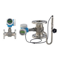
VORTEX FLOWMETER
Brand:
TLV
| Category:
Measuring Instruments
| Size: 2 MB
Table of Contents
Table of Contents
3
About this Document
6
Document Function
6
Symbols
6
Safety Symbols
6
Electrical Symbols
6
Symbols in Graphics
7
Standard Documentation
8
Supplementary Device-Dependent Documentation
8
Safety Instructions
9
Requirements for the Personnel
9
Designated Use
9
Workplace Safety
10
Operational Safety
10
Product Safety
10
Security
10
Device-Specific IT Security
10
Protecting Access Via Hardware Write Protection
11
Protecting Access Via a Password
11
2.8 Vibrations
12
2.9 Preventing Excessive Flow
12
Pulsating Influences
12
Prevent Mixed Phase Flowy
12
2.12 Ensure Pipe Is Flooded
12
2.13 Bypass Lines
12
Product Description
13
Product Design
13
Incoming Acceptance and Product
14
Incoming Acceptance
14
Product Identification
15
Sensor Nameplate (Remote Version)
16
Nameplate for TEG
17
Storage and Transport
18
Storage Conditions
18
Transporting the Product
18
Measuring Devices Without Lifting Lugs
18
Measuring Devices with Lifting Lugs
19
Mounting Position
20
Environment and Process Requirements
25
Ensuring Accurate Measurements
26
Mounting the Measuring Device
27
Preparing the Measuring Device
27
Mounting the Pressure Measuring Unit
28
Mounting the Transmitter of the Remote Version
30
Turning the Transmitter Housing
31
Post-Installation Check
33
Electrical Connection Connection Conditions
34
Connecting Cable Requirements
34
Connecting Cable for Remote Version
35
Terminal Assignment
36
Requirements for the Supply Unit
38
Connecting the Measuring Device
39
Connecting the Compact Version
40
Connecting the Connecting Cable for the Pressure Measuring Cell
46
Ensuring Potential Equalization
46
Ensuring the Degree of Protection
46
Post-Connection Check
47
7.5 Connecting to TLV EC351 Flow Computer
48
Operation Options
49
Overview of Operation Options
49
Operating Philosophy
51
Access to the Operating Menu Via the Local
52
Operational Display
52
Operating Elements
57
Opening the Context Menu
57
Navigating and Selecting from List
59
Calling the Parameter Directly
59
Changing the Parameters
61
User Roles and Related Access Authorization
62
Disabling Write Protection Via Access Code
62
Enabling and Disabling the Keypad Lock
63
Access to the Operating Menu Via the Operating Tool
63
Connecting the Operating Tool
63
System Integration
65
Overview of Device Description Files
65
Current Version Date for the Device
65
Commissioning
66
Function Check
66
Switching on the Measuring Device
66
Setting the Operating Language
66
Configuring the Measuring Device
67
Defining the Tag Name
68
Setting the System Units
68
Selecting and Setting the Medium
72
Configuring the Current Input
75
Configuring the Current Output
76
Configuring the Pulse/Frequency/Switch Output
78
Configuring the Local Display
83
Configuring the Low Flow Cut off
85
Advanced Settings
86
Setting the Medium Properties
87
Performing External Compensation
92
Carrying out a Sensor Adjustment
94
Configuring the Totalizer
97
Carrying out Additional Display Configurations
98
Configuration Management
101
Using Parameters for Device Administration
102
Configuration Management
102
Function Scope of the "Configuration Management" Parameter
103
Simulation
104
Protecting Settings from Unauthorized Access
106
Write Protection Via Access Code
106
Write Protection Via Write Protection Switch
107
Application-Specific Commissioning
108
Steam Application
108
Liquid Application
109
Gas Applications
110
Calculation of the Measured Variables
111
Operation
114
Reading the Device Locking Status
114
Adjusting the Operating Language
114
Configuring the Display
114
11.4 Reading Measured Values
114
Process Variables
115
11.4.2 "Totalizer" Submenu
118
Input Values
118
Output Values
119
Adapting the Measuring Device to the Process Conditions
120
Performing a Totalizer Reset
120
Function Scope of the "Control Totalizer" Parameter
121
Function Scope of the "Reset All Totalizers" Parameter
121
Diagnostics and Troubleshooting
122
General Troubleshooting
122
Diagnostic Information on Local Display
124
Diagnostic Message
124
Calling up Remedial Measures
126
Adapting the Diagnostic Information
127
Adapting the Diagnostic Behavior
127
Adapting the Status Signal
128
Overview of Diagnostic Information
128
Operating Conditions for Displaying the Following Diagnostics Information
132
Emergency Mode in the Event of Pressure Compensation
132
Emergency Mode in Event of Temperature Compensation
132
Pending Diagnostic Events
133
Diagnostic List
133
Event Logbook
134
Reading out the Event Logbook
134
Filtering the Event Logbook
134
Overview of Information Events
135
Resetting the Measuring Device
136
Function Scope of the "Device Reset" Parameter
136
12.9 Device Information
136
Maintenance
139
Maintenance Tasks
139
Exterior Cleaning
139
13.1.2 Interior Cleaning
139
13.1.3 Replacing Seals
139
13.1.4 Adjusting the Pressure Measuring Cell
139
Repair
140
General Notes
140
Repair and Conversion Concept
140
Notes for Repair and Conversion
140
Spare Parts
140
Disposal
141
Removing the Measuring Device
141
Disposing of the Measuring Device
141
Accessories
142
Device-Specific Accessories
142
For the Transmitter
142
For the Sensor
143
Technical Data
144
Application
144
Function and System Design
144
Input
144
Output
151
Power Supply
153
Performance Characteristics
156
Installation
160
Environment
161
Process
163
16.10 Mechanical Construction
165
16.11 Operability
172
Certificates and Approvals
174
16.13 Application Packages
174
16.14 Accessories
174
16.15 Supplementary Documentation
175
Flow Rate Data
176
Tlv Express Limited Warranty
178
Services
180
Advertisement
TLV EF200R-C Technical Information (77 pages)
Vortex flowmeter
Brand:
TLV
| Category:
Measuring Instruments
| Size: 2 MB
Table of Contents
Table of Contents
2
About this Document
3
Function and System Design
4
Measuring Principle
4
Measuring System
7
Input
8
Measured Variable
8
Measuring Range
8
Operable Flow Range
13
Output
13
Output Signal
13
Signal on Alarm
15
Load
16
Low Flow Cut off
16
Galvanic Isolation
16
Protocol-Specific Data
16
Power Supply
17
Terminal Assignment
17
Supply Voltage
19
Power Consumption
20
Current Consumption
20
Power Supply Failure
21
Electrical Connection
21
Potential Equalization
23
Terminals
23
Cable Entries
23
Cable Specification
23
Overvoltage Protection
24
Performance Characteristics
24
Maximum Measured Error
25
Repeatability
28
Response Time
28
Influence of Ambient Temperature
29
Installation
29
Mounting Location
29
Orientation
30
Inlet and Outlet Runs
32
Length of Connecting Cable
34
Mounting the Transmitter Housing
34
Environment
35
Ambient Temperature Range
35
Storage Temperature
35
Climate Class
35
Degree of Protection
35
Vibration- and Shock-Resistance
35
Process
36
Medium Temperature Range
36
Pressure-Temperature Ratings
36
Nominal Pressure of Sensor
39
Pressure Specifications
39
Pressure Loss
40
Thermal Insulation
40
Mechanical Construction
41
Dimensions in si Units
41
Weight
64
Materials
68
Operability
71
Operating Concept
71
Languages
71
Local Operation
71
Remote Operation
72
Certificates and Approvals
72
CE Mark
72
RCM-Tick Symbol
72
HART Certification
72
Pressure Equipment Directive
72
Experience
73
Other Standards and Guidelines
73
Supplementary Documentation
74
Standard Documentation
74
Registered Trademarks
74
Tlv Express Limited Warranty
75
Service
77
Advertisement
Related Products
TLV EF200F-C
TLV EF200W-C
TLV EF200
TLV iTrapSensor iT5-ZB
TLV Categories
Control Unit
Industrial Equipment
Plumbing Product
Water Pump
Water Filtration Systems
More TLV Manuals
Login
Sign In
OR
Sign in with Facebook
Sign in with Google
Upload manual
Upload from disk
Upload from URL