
Related Manuals for TLV EF200W-C


Summary of Contents for TLV EF200W-C
- Page 1 172-65762M-00 (EF200W-C Vortex flowmeter) 8 February 2021 Vortex flowmeter EF200W-C Copyright © 2021 by TLV CO., LTD. All rights reserved...
-
Page 2: Table Of Contents
EF200W-C Table of contents About this document Vibration- and shock-resistance Electromagnetic compatibility (EMC) Symbols Process Function and system design Medium temperature range Measuring principle Pressure-temperature ratings Measuring system Nominal pressure of sensor Pressure loss Input Thermal insulation Measured variable Measuring range Mechanical construction Operable flow range Dimensions in SI units Dimensions in US units Output Weight Output signal Materials Signal on alarm Load Operability Low flow cut off Operating concept Galvanic isolation Languages Protocol-specific data Local operation Remote operation Power supply Terminal assignment Certificates and approvals Supply voltage CE mark... -
Page 3: About This Document
EF200W-C About this document Symbol Meaning Direct current Alternating current Direct current and alternating current Ground connection A grounded terminal which, as far as the operator is concerned, is grounded via a grounding system. Protective Earth (PE) A terminal which must be connected to ground prior to establishing any other connections. The ground terminals are situated inside and outside the device: • Inner ground terminal: Connects the protectiv earth to the mains supply. • Outer ground terminal: Connects the device to the plant grounding system. Symbols for certain types of information Symbol Meaning Permitted Procedures, processes or actions that are permitted. Preferred Procedures, processes or actions that are preferred. Forbidden Procedures, processes or actions that are forbidden. Indicates additional information. Reference to documentation. Reference to page. Reference to graphic. Visual inspection. Symbols in graphics... -
Page 4: Function And System Design
EF200W-C Function and system design Measuring principle Vortex meters work on the principle of the Karman vortex street . When fluid flows past a bluff body, vortices are alternately formed on both sides with opposite directions of rotation. These vortices each generate a local low pressure. The pressure fluctuations are recorded by the sensor and converted to electrical pulses. The vortices develop very regularly within the permitted application limits of the device. Therefore, the frequency of vortex shedding is proportional to the volume flow. A0033465 Sample graphic The calibration factor (K-factor) is used as the proportional constant: Pulses K-Factor = Unit Volume [m³] Within the application limits of the device, the K-factor only depends on the geometry of the device. It is for Re > 20 000: • Independent of the flow velocity and the fluid properties viscosity and density • Independent of the type of substance under measurement: steam, gas or liquid The primary measuring signal is linear to the flow. After production, the K-factor is determined in the factory by means of calibration. It is not subject to long-time drift or zero-point drift. The device does not contain any moving parts and does not require any maintenance. The capacitance sensor The sensor of a vortex flowmeter has a major influence on the performance, robustness and reliability of the entire measuring system. The robust DSC sensor is: • burst-tested •... - Page 5 EF200W-C Temperature measurement The measuring device can also measure the temperature of the medium. The temperature is measured via Pt 1000 temperature sensors. These are located in the paddle of the DSC sensor and are therefore in the direct vicinity of the fluid. A0034068 DSC sensor Lifelong calibration Experience has shown that recalibrated measuring devices demonstrate a very high degree of stability compared to their original calibration: The recalibration values were all within the original measuring accuracy specifications of the devices. This applies to the measured volume flow, the device's primary measured variable. Various tests and simulation have shown that once the radii of the edges on the bluff body are less than 1 mm (0.04 in), the resulting effect does not have a negative impact on accuracy. If the radii of the edges on the bluff body do not exceed 1 mm (0.04 in), the following general statements apply (in the case of non-abrasive and non-corrosive media, such as in most water and steam applications): • The measuring device does not display an offset in the calibration and the accuracy is still guaranteed. • All the edges on the bluff body have a radius that is typically smaller in size. As the measuring devices are naturally also calibrated with these radii, the measuring device remains within the specified accuracy rating provided that the additional radius that is produced as a result of wear and tear does not exceed 1 mm (0.04 in). Consequently, it can be said that the product line offers lifelong calibration if the measuring device is used in non-abrasive and non-corrosive media. Air and industrial gases The measuring device enables users to calculate the density and energy of air and industrial gases. The calculations are based on time-tested standard calculation methods. It is possible to automatically compensate for the effect of pressure and temperature via an external or constant value. This makes it possible to output the energy flow, standard volume flow and mass flow of the following gases: •...
-
Page 6: Measuring System
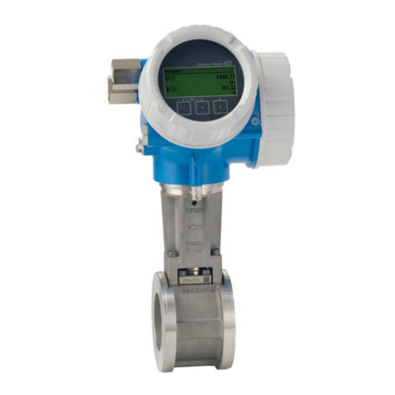
EF200W-C Measuring system The device consists of a transmitter and a sensor. Two device versions are available: • Compact version ‒ transmitter and sensor form a mechanical unit. • Remote version - transmitter and sensor are mounted in separate locations. Transmitter EF200-C Device versions and materials: • Compact or remote version, aluminum coated: Aluminum, AlSi10Mg, coated Configuration: • Via four-line local display with key operation or via four-line, • Via operating tools A0013471 Sensor EF200W-C Disc (wafer version): • Nominal diameter range: DN 15 to 150 (½ to 6") • Materials: Measuring tubes: stainless steel, CF3M/1.4408 A0009922 Input Measured variable Direct measured variables Order code for "Sensor version; DSC sensor; measuring tube" Measured variable Description Mass; 316L; 316L (integrated temperature measurement) •... -
Page 7: Measuring Range
EF200W-C Measuring range The measuring range is dependent on the nominal diameter, the fluid and environmental influences. The following specified values are the largest possible flow measuring ranges (Qmin to Qmax) for each nominal diameter. Depending on the fluid properties and environmental influences, the measuring range may be subject to additional restrictions. Additional restrictions apply to both the lower range value and the upper range value. Flow measuring ranges in SI units Liquids Gas/steam [mm] [m³/h] [m³/h] 0.06 to 4.9 0.3 to 25 0.18 to 15 0.9 to 130 0.45 to 37 2.3 to 310 0.75 to 62 3.8 to 820 1.7 to 140 8.5 to 1 2.9 to 240 15 to 3 6.7 to 540 33 to 7 Flow measuring ranges in US units Liquids Gas/steam [in] [ft³/min] [ft³/min] ½ 0.035 to 2.9 0.18 to 15 0.11 to 8.8... - Page 8 EF200W-C Flow velocity A0033469 Internal diameter of measuring tube (corresponds to dimension K→ See page 34) Velocity in mating pipe Flow The internal diameter of measuring tube D is denoted in the dimensions as dimension K.→ See page 34. Calculation of flow velocity: · 4 Q [ ³ · v [m/s] = π · D [m] ² 3600 [s/h] 4 · Q [ /min] ft³ · v [ /s] = 60 [s/min] π · D [ft] ² A0034301 Lower range value A restriction applies to the lower range value due to the turbulent flow profile, which only occurs...
- Page 9 EF200W-C 5000 · · D [m] · π μ · s] [m /h] = ³ · 3600 [s/h] Re = 5000 · ρ [kg/m ] ³ 5000 · · D [ft] · π μ [lbf · s/ft ] ² [ /h] = ³ · 60 [s/min] Re = 5000 · ρ [lbm/ ] ³...
- Page 10 EF200W-C The effective lower range value Q is determined using the largest of the three values Qmin, and Q Re =5000 AmpMin [m /h] ³ [m /h] ³ [m /h] = max ³ Re = 5000 [m /h] ³ AmpMin [ /min] [ /min] ³ Re = 5000 [ /min] AmpMin A0034313 Effective lower range value Minimum measurable flow rate Flow rate is dependent on the Reynolds number = 5000 Minimum measurable flow rate based on signal amplitude AmpMin Upper range value The measuring signal amplitude must be below a certain limit value to ensure that the signals can be evaluated without error. This results in a maximum permitted flow rate Q...
-
Page 11: Operable Flow Range
EF200W-C Mach number Flow velocity Sound velocity The corresponding flow rate can be derived using the nominal diameter. 0.3 · c [m/s] · · D [m] π ² [m /h] = ³ · 3600 [s/h] Ma = 0.3 0.3 · c [ft/s] · · D [ft] π ² [ /min] = ³ · 60 [s/min] Ma = 0.3 A0034337 Restricted upper range value is dependent on Mach number Ma = 0.3 Sound velocity Internal diameter of measuring tube (corresponds to dimension K→ See page 34) ρ Density The effective upper range value Q is determined using the smallest of the three values High and Q . ... -
Page 12: Output
EF200W-C Output Output signal Current output Current output 1 4-20 mA (passive) Resolution < 1 µA Damping Adjustable: 0.0 to 999.9 s Assignable measured • Volume flow variables • Corrected volume flow • Mass flow • Flow velocity • Temperature • Pressure • Calculated saturated steam pressure • Total mass flow • Energy flow • Heat flow difference Pulse/frequency/switch output Function Can be set to pulse, frequency or switch output Version Passive, open collector Maximum input values... -
Page 13: Signal On Alarm
EF200W-C Switch output Switching behavior Binary, conductive or non-conductive Switching delay Adjustable: 0 to 100 s Number of switching Unlimited cycles Assignable functions • Off • On • Diagnostic behavior • Limit value • Volume flow • Corrected volume flow • Mass flow • Flow velocity • Temperature • Calculated saturated steam pressure • Total mass flow • Energy flow • Heat flow difference • Pressure • Reynolds number •... -
Page 14: Load
EF200W-C Local display Plain text display With information on cause and remedial measures Status signal as per NAMUR recommendation NE 107 Interface/protocol • Via digital communication: • HART protocol • Via service interface CDI service interface Plain text display With information on cause and remedial measures Additional information on remote operation → See page 50 Load for current output: 0 to 500 Ω, depending on the external supply voltage of the power supply Load unit Calculation of the maximum load Depending on the supply voltage of the power supply unit (U ), the maximum load (R ) including line resistance must be observed to ensure adequate terminal voltage at the device. In doing so, observe the minimum terminal voltage • For U = 17.9 to 18.9 V: R (U - 17.9 V): 0.0036 A • For U = 18.9 to 24 V: R (U - 13 V): 0.022 A... -
Page 15: Low Flow Cut Off
EF200W-C Low flow cut off The switch points for low flow cut off are preset and can be configured. Galvanic isolation All inputs and outputs are galvanically isolated from one another. Protocol-specific data HART Manufacturer ID 0x11 Device type ID 0x0038 HART protocol revision Device description files Consult TLV for more information. (DTM, DD ) HART load • Min. 250 Ω • Max. 500 Ω Power supply Terminal assignment Transmitter Connection versions ‒ ‒ A0033475 Maximum number of terminals Terminals 1 to 4: Without integrated overvoltage protection Output 1 (passive): supply voltage and signal transmission Output 2 (passive): supply voltage and signal transmission Ground terminal for cable shield... - Page 16 EF200W-C Connecting cable for remote version Transmitter and sensor connection housing In the case of the remote version, the sensor and transmitter are mounted separately from on another and connected by a connecting cable. Connection is performed via the sensor connection housing and the transmitter housing. Terminals are always used to connect the connecting cable in the sensor connection housing (tightening torques for screws for cable strain relief: 1.2 to 1.7 Nm). Connecting cable ‒ ‒ A0033476 Terminals for connection compartment in the transmitter wall holder and the sensor connection housing Terminals for connecting cable Grounding via the cable strain relief Terminal number Assignment Cable color Connecting cable Supply voltage Brown Grounding White RS485 (+) Yellow RS485 (‒) Green...
-
Page 17: Supply Voltage
EF200W-C Supply voltage Transmitter An external power supply is required for each output. 1) Supply voltage for a compact version without a local display Output Minimum Maximum 2) terminal voltage terminal voltage 4-20 mA HART, pulse/frequency/switch output DC 12 V DC 35 V In event of external supply voltage of the power supply unit with load The minimum terminal voltage increases if local operation is used: see the following table Voltage drop 2.2 to 3 V for 3.59 to 22 mA Increase in minimum terminal voltage Increase in minimum Display; operation terminal voltage Local operation + DC 1 V Power consumption Transmitter Order code for "Output; input" Maximum power consumption 4-20 mA HART, pulse/ • Operation with output 1: 770 mW frequency/switch output • Operation with output 1 and 2: 2 770 mW Current consumption Current output For every 4-20 mA or 4-20 mA current output: 3.6 to 22.5 mA... -
Page 18: Power Supply Failure
EF200W-C Power supply failure • Totalizers stop at the last value measured. • Depending on the device version, the configuration is retained in the device memoryor in the pluggable data memory (HistoROM DAT). • Error messages (incl. total operated hours) are stored. Electrical connection Connecting the transmitter A0033480 Cable entries for inputs/outputs Remote version connection Connecting cable A0033481 Connecting cable connection Wall holder with connection compartment (transmitter) Connecting cable Sensor connection housing Terminals are always used to connect the connecting cable in the sensor connection housing (tightening torques for screws for cable strain relief: 1.2 to 1.7 Nm). - Page 19 EF200W-C Connection examples Current output 4-20 mA 4...20 mA A0028762 Connection example for 4 to 20 mA HART current output (passive) Automation system with current input (e.g. PLC) Power supply Cable shield provided at one end. The cable shield must be grounded at both ends to comply with EMC requirements; observe cable specifications Analog display unit: observe maximum load Transmitter Pulse/frequency output 12345 A0028761 Connection example for pulse/frequency output (passive) Automation system with pulse/frequency input (e.g. PLC) Power supply Transmitter: Observe input values Switch output A0028760 Connection example for switch output (passive) Automation system with switch input (e.g. PLC) Power supply Transmitter: Observe input values...
-
Page 20: Potential Equalization
EF200W-C Potential equalization Requirements Please consider the following to ensure correct measurement: • Same electrical potential for the fluid and sensor • Remote version: same electrical potential for the sensor and transmitter • Company-internal grounding concepts • Pipe material and grounding Terminals • For device version without integrated overvoltage protection: plug-in spring terminals for wire cross-sections 0.5 to 2.5 mm (20 to 14 AWG) • For device version with integrated overvoltage protection: screw terminals for wire cross-sections 0.2 to 2.5 mm (24 to 14 AWG) Cable entries • Thread for cable entry: G ½" Cable specification Permitted temperature range • The installation guidelines that apply in the country of installation must be observed. • The cables must be suitable for the minimum and maximum temperatures to be expected. Signal cable Current output 4 to 20 mA A shielded cable is recommended. Observe grounding concept of the plant. -
Page 21: Overvoltage Protection
EF200W-C Overvoltage protection The device can be ordered with integrated overvoltage protection for diverse approvals: Order code for "Accessory mounted", option NA "Overvoltage protection" Input voltage range Values correspond to supply voltage specifications → See page 17 Resistance per channel 2 · 0.5 Ω max. DC sparkover voltage 400 to 700 V Trip surge voltage < 800 V Capacitance at 1 MHz < 1.5 pF Nominal discharge current 10 kA (8/20 μs) Temperature range ‒40 to +85 °C (‒40 to +185 °F) The voltage is reduced by the amount of the internal resistance I R Performance characteristics Reference operating • Error limits following ISO/DIN 11631 conditions • +20 to +30 °C (+68 to +86 °F) • 2 to 4 bar (29 to 58 psi) • Calibration system traceable to national standards • Calibration with the process connection corresponding to the particular standard Maximum measured error Base accuracy o.r. = of reading... - Page 22 EF200W-C Volume flow Medium type Incompressible Compressible Reynolds number range Measured value deviation Standard Standard to Re < 10 % < 10 % to Re < 0.75 % < 1.0 % Accuracy specifications valid up to 75 m/s (246 ft/s) Temperature • Saturated steam and liquids at room temperature, if T > 100 °C (212 °F) applies: < 1 °C (1.8 °F) • Gas: < 1 % o.r. [K] • Volume flow if > 70 m/s (230 ft/s): 2 % o.r. Rise time 50 % (stirred under water, following IEC 60751): 8 s Mass flow saturated steam Flow velocity Temperature Reynolds number Maximum Standard [m/s (ft/s)] [°C (°F)] range measured error 20 to 50 150 (302) or to Re < 1.7 %...
- Page 23 EF200W-C Mass flow (user-specific liquids) Example • Acetone is to be measured at fluid temperatures from +70 to +90 °C (+158 to +194 °F). • For this purpose, the Reference temperature parameter (7703) (here 80 °C (176 °F)), Reference density parameter (7700) (here 720.00 kg/m ) and Linear expansion coefficient parameter (7621) (here 18.0298 × 10 1/°C) must be entered in the transmitter. • The overall system uncertainty, which is less than 0.9 % for the example above, is comprised of the following measurement uncertainties: uncertainty of volume flow measurement, uncertainty of temperature measurement, uncertainty of the density-temperature correlation used (including the resulting uncertainty of density). Mass flow (other media) Depends on the selected fluid and the pressure value, which is specified in the parameters. Individual error analysis must be performed. Diameter mismatch correction The measuring device can correct shifts in the calibration factor which are caused, for example, by a diameter mismatch between the device flange (e.g. ASME B16.5/Sch. 80, DN 50 (2")) and the mating pipe (e.g. ASME B16.5/Sch. 40, DN 50 (2")). Only apply diameter mismatch correction within the following limit values (listed below) for which test measurements have also been performed. If the standard internal diameter of the ordered process connection differs from the internal diameter of the mating pipe, an additional measuring uncertainty of approx. 2 % o.r. must be expected. Example Influence of the diameter mismatch without using the correction function: • Mating pipe DN 100 (4"), Schedule 80 • Device flange DN 100 (4"), Schedule 40 • This installation position results in a diameter mismatch of 5 mm (0.2 in). If the correction function is not used, an additional measuring uncertainty of approx. 2% o.r. must be expected. • If the basic conditions are met and the feature is enabled, the additional measuring uncertainty is 1 % o.r.
-
Page 24: Repeatability
EF200W-C Repeatability o.r. = of reading ±0.2 % o.r. Response time If all the configurable functions for filter times (flow damping, display damping, current output time constant, frequency output time constant, status output time constant) are set to 0, in the event of vortex frequencies of 10 Hz and higher a response time of max(T 100 ms) can be expected. ν, In the event of measuring frequencies < 10 Hz, the response time is > 100 ms and can be up to 10 s. is the average vortex period duration of the flowing fluid. ν Influence of ambient Current output temperature o.r. = of reading Additional error, in relation to the span of 16 mA: Temperature coefficient at 0.02 %/10 K zero point (4 mA) Temperature coefficient 0.05 %/10 K with span (20 mA) Pulse/frequency output o.r. = of reading Temperature coefficient Max. ±100 ppm o.r. Installation Mounting location A0042128 Installation suitable for gases and steam Installation not suitable for liquids Orientation The direction of the arrow on the sensor nameplate helps you to install the sensor according to the... - Page 25 EF200W-C Vortex meters require a fully developed flow profile as a prerequisite for correct volume flow measurement. Therefore, please note the following: Orientation Recommendation Compact version Remote version 1) A Vertical orientation (liquids) A0015591 A Vertical orientation (dry gases) A0015591 A0041785 2) 3) B Horizontal orientation, transmitter head up A0015589 4) C Horizontal orientation, transmitter head down A0015590 D Horizontal orientation, transmitter head at side A0015592 In the case of liquids, there should be upward flow in vertical pipes to avoid partial pipe filling (Fig. A). Disruption in flow measurement! Danger of electronics overheating! If the fluid temperature is 200 °C (392 °F), orientation B is not permitted for the wafer version (EF200W-C) with nominal diameters of DN 100 (4") and DN 150 (6"). In the case of hot media (e.g. steam or fluid temperature (TM) 200 °C (392 °F): orientation C or D In the case of very cold media (e.g. liquid nitrogen): orientation B or D...
-
Page 26: Inlet And Outlet Runs
EF200W-C Inlet and outlet runs To attain the specified level of accuracy of the measuring device, the inlet and outlet runs mentioned below must be maintained at the very minimum. 25 × DN 15 × DN 5 × DN 5 × DN 25 × DN 5 × DN 20 × DN 5 × DN 40 × DN 5 × DN 20 × DN 5 × DN 50 × DN 5 × DN 17 × DN + 8 × h 5 × DN h: differece in expansion DN 25 (1"):... - Page 27 EF200W-C 2 × DN 8 × DN 5 × DN 5 × DN 8 × DN 5 × DN Flow conditioner Flow conditioner 5 × DN 8 × DN 5 × DN 2 × DN 8 × DN 5 × DN Flow conditioner Flow conditioner 2 × DN 8 × DN 5 × DN 5 × DN 8 × DN 5 × DN Flow conditioner...
-
Page 28: Mounting Kit For Disc (Wafer Version)
EF200W-C Outlet runs when installing external devices If installing an external device, observe the specified distance. 3…5 × DN 4…8 × DN A0019205 Pressure Temperature device Mounting kit for disc (wafer The centering rings supplied are used to mount and center the wafer-style devices. version) A mounting kit comprises: • Tie rods • Seals • Nuts • Washers A0019875 Mounting kit for wafer version Nut, washer, tie rod Seal Centering ring (is supplied with the measuring device) Length of connecting cable To ensure correct measuring results when using the remote version, • observe the maximum permitted cable length: L = 30 m (90 ft). max • The value for the cable length must be calculated if the cable cross-section differs from the specification. - Page 29 EF200W-C Mounting the transmitter Wall mounting housing 19 (0.6) 80 (3.15) mm (in) A0033484 Post mounting 20 70 4 x SW 13 mm (in) A0033486 1 Mounting kit for post mounting...
-
Page 30: Environment
EF200W-C Environment Ambient temperature range Compact version Measuring device ‒40 to +80 °C (‒40 to +176 °F) Local display ‒40 to +70 °C (‒40 to +158 °F) At temperatures < ‒20 °C (‒4 °F), depending on the physical characteristics involved, it may no longer be possible to read the liquid crystal display. Remote version Transmitter ‒40 to +80 °C (‒40 to +176 °F) ‒40 to +85 °C (‒40 to +185 °F) Sensor Local display ‒40 to +70 °C (‒40 to +158 °F) At temperatures < ‒20 °C (‒4 °F), depending on the physical characteristics involved, it may no longer be possible to read the liquid crystal display. ► If operating outdoors: Avoid direct sunlight, particularly in warm climatic regions. You can order a weather protection cover from TLV. Storage temperature ‒50 to +80 °C (‒58 to +176 °F) Climate class DIN EN 60068-2-38 (test Z/AD) Degree of protection Transmitter • As standard: IP66/67, type 4X enclosure • When housing is open: IP20, type 1 enclosure • Display module: IP20, type 1 enclosure Sensor IP66/67, type 4X enclosure... -
Page 31: Process
EF200W-C Process Medium temperature range DSC sensor Description Medium temperature range Mass; 316L; 316L ‒200 to +400 °C (‒328 to +750 °F), stainless steel Capacitance sensor Seals Description Medium temperature range Graphite (standard) ‒200 to +400 °C (‒328 to +752 °F) Pressure-temperature The following pressure/temperature diagrams apply to all pressure-bearing parts of the device and ratings not just the process connection. The diagrams show the maximum permissible medium pressure depending on the specific medium temperature. The pressure-temperature rating for the specific measuring device is programmed into the software. If values exceed the curve range a warning is displayed. Depending on the system configuration and sensor version, the pressure and temperature are determined by entering, reading in or calculating values. Wafer flange for pressure ratings according to EN 1092-1, material group 13E0 [psi] [psi] [bar] [bar] PN40 PN40 PN25 PN25 PN16 PN16 PN10 PN10 -200 -200... -
Page 32: Nominal Pressure Of Sensor
EF200W-C Wafer flange for pressure ratings according to ASME B16.5, material group 2.2 [psi] [psi] [bar] [bar] Class 300 Class 300 PN40 PN40 Class 150 Class 150 PN40 PN40 [°C] [°C] -200 -200 -100 -100 [°F] [°F] -400 -200 -200 A0034040-EN Material: stainless steel, CF3M/1.4408 Wafer flange for connection to flanges according to JIS B2220... -
Page 33: Pressure Loss
EF200W-C Pressure loss Consult TLV for a precise calculation. Thermal insulation For optimum temperature measurement and mass calculation, heat transfer at the sensor must be avoided for some fluids. This can be ensured by installing thermal insulation. A wide range of materials can be used for the required insulation. This applies for: • Compact version • Remote sensor version The maximum insulation height permitted is illustrated in the diagram: max insulation height A0019212 Maximum insulation height ► When insulating, ensure that a sufficiently large area of the housing support remains exposed. The uncovered part serves as a radiator and protects the electronics from overheating and excessive cooling. -
Page 34: Mechanical Construction
EF200W-C Mechanical construction Dimensions in SI units Compact version A0033795 Wafer flange according to: • EN 1092-1-B1 (DIN 2501): PN 10/16/25/40 • ASME B16.5: Class 150/300, Schedule 40 • JIS B2220: 10/20K, Schedule 40 1.4404/F316/F316L 1) 1) 2) 2) 3) K (D [mm] [mm] [mm] [mm] [mm] [mm] [mm] [mm] [mm] [mm] [mm] [mm] [mm] 4) 140.2 51.7 88.5... - Page 35 EF200W-C Transmitter remote version A0033796 1) 1) 2) 3) 3) [mm] [mm] [mm] [mm] [mm] [mm] [mm] 140.2 51.7 88.5 159.9 For version with overvoltage protection: value + 8 mm For version without local display: value - 10 mm For version without local display: value - 7 mm...
- Page 36 EF200W-C Sensor remote version A0033798 Wafer flange according to: • EN 1092-1-B1 (DIN 2501): PN 10/16/25/40 • ASME B16.5: Class 150/300, Schedule 40 • JIS B2220: 10/20K, Schedule 40 1.4404/F316/F316L 1) K (D [mm] [mm] [mm] [mm] [mm] [mm] [mm] [mm] [mm] [mm] [mm] 2) 107.3 47.3 23.4 222.8 246.2 94.5 16.5 2) 107.3 47.3 32.4 232.3 264.7 94.5...
- Page 37 EF200W-C Accessories Flow conditioner A0033504 Used in combination with flanges according to DIN EN 1092-1: PN 10 1.4404 (316, 316L) 1) 2) Centering diameter / D2 [mm] [mm] [mm] 54.3 74.3 95.3 110.0 145.3 10.1 165.3 13.3 221.0 20.0 The flow conditioner is fitted at the outer diameter between the bolts. The flow conditioner is fitted at the indentations between the bolts.
- Page 38 EF200W-C Used in combination with flanges according to DIN EN 1092-1: PN 16 1.4404 (316, 316L) 1) 2) Centering diameter / D2 [mm] [mm] [mm] 54.3 74.3 95.3 110.0 145.3 10.1 165.3 13.3 221.0 20.0 The flow conditioner is fitted at the outer diameter between the bolts. The flow conditioner is fitted at the indentations between the bolts. Used in combination with flanges according to DIN EN 1092-1: PN 25 1.4404 (316, 316L) 1) 2) Centering diameter / D2 [mm] [mm] [mm] 54.3 74.3 95.3 110.0 145.3 10.1 171.3 13.3 227.0 20.0...
- Page 39 EF200W-C Used in combination with flanges according to ASME B16.5: Class 150 1.4404 (316, 316L) 1) 2) Centering diameter / D2 [mm] [mm] [mm] 50.1 69.2 88.2 106.6 138.4 10.1 176.5 13.3 223.5 20.0 The flow conditioner is fitted at the outer diameter between the bolts. The flow conditioner is fitted at the indentations between the bolts. Used in combination with flanges according to ASME B16.5: Class 300 1.4404 (316, 316L) 1) 2) Centering diameter / D2 [mm] [mm] [mm] 56.5 74.3 97.7 113.0 151.3 10.1 182.6 13.3 252.0 20.0...
- Page 40 EF200W-C Used in combination with flanges according to JIS B2220: 20K 1.4404 (316, 316L) 1) 2) Centering diameter / D2 [mm] [mm] [mm] 60.3 76.3 91.3 106.6 142.3 10.1 167.3 13.3 240.0 20.0 The flow conditioner is fitted at the outer diameter between the bolts. The flow conditioner is fitted at the indentations between the bolts. Dimensions in US units Compact version A0033795 Wafer flange according to: • EN 1092-1-B1 (DIN 2501): PN 10/16/25/40 • ASME B16.5: Class 150/300, Schedule 40 • JIS B2220: 10/20K, Schedule 40 1.4404/F316/F316L 1) 1) 2) 2) ...
- Page 41 EF200W-C Transmitter remote version A0033796 1) 1) 2) 3) 3) [in] [in] [in] [in] [in] [in] [in] 5.52 2.04 3.48 4.21 7.52 For version with overvoltage protection: value + 0.31 in For version without local display: value - 0.39 in For version without local display: value - 0.28 in...
- Page 42 EF200W-C Sensor remote version A0033798 Wafer flange according to: • EN 1092-1-B1 (DIN 2501): PN 10/16/25/40 • ASME B16.5: Class 150/300, Schedule 40 • JIS B2220: 10/20K, Schedule 40 1.4404/F316/F316L 1) K (D [in] [in] [in] [in] [in] [in] [in] [in] [in] [in] [in] ½ 4.22 2.36 1.86 0.92 8.77 9.69 3.72 0.65 2.56 1.77 4.22 2.36 1.86 1.28...
- Page 43 EF200W-C Accessories Flow conditioner A0033504 Used in combination with flanges according to ASME B16.5: Class 150 1.4404 (316, 316L) 1) 2) Centering diameter / D2 [in] [in] [in] ½ 1.97 0.08 2.72 0.14 1½ 3.47 0.21 4.09 0.27 5.45 0.40 6.95 0.52 8.81 0.79 The flow conditioner is fitted at the outer diameter between the bolts. The flow conditioner is fitted at the indentations between the bolts. Used in combination with flanges according to ASME B16.5: Class 300 1.4404 (316, 316L) 1) 2) Centering diameter / D2 [in] [in] [in] ½...
- Page 44 EF200W-C Weight data: • Including the transmitter: 1.8 kg (4.0 lb): • Excluding packaging material Weight in SI units Weight [kg] [mm] Aluminum, coated, compact" Weight in US units Weight [lbs] [in] Auminum, coated, compact" ½ 1½ 12.4 14.6 20.2 Transmitter remote version Wall-mount housing • 2.4 kg (5.2 lb) Sensor remote version Weight data: • Including sensor connection housing: • 0.8 kg (1.8 lb) • Excluding the connecting cable • Excluding packaging material...
- Page 45 EF200W-C Weight in SI units Weight [kg] [mm] Aluminum, coated, remote Weight in US units Weight [lbs] [in] Aluminum, coated, remote ½ 1½ 10.0 12.3 17.3...
- Page 46 EF200W-C Accessories Flow conditioner Weight in SI units 1) Pressure rating Weight [mm] [kg] PN 10 to 40 0.04 PN 10 to 40 PN 10 to 40 PN 10 to 40 PN 10 to 40 PN10 to 40 PN 10/16 PN 25/40 EN (DIN) 1) Pressure rating Weight [mm] [kg] Class 150 0.03 Class 300 0.04 Class 150 Class 300 Class 150 Class 300 Class 150 Class 300 Class 150 Class 300 Class 150 Class 300 Class 150 Class 300 ASME 1)
- Page 47 EF200W-C Weight in US units 1) Pressure rating Weight [in] [lbs] ½ Class 150 0.07 Class 300 0.09 Class 150 Class 300 1½ Class 150 Class 300 Class 150 Class 300 Class 150 Class 300 Class 150 Class 300 Class 150 14.0 Class 300 16.0 ASME t t i Compact version • Aluminum, AlSi10Mg, coated • Window material: glass Remote version • Aluminum, AlSi10Mg, coated • Window material: glass Cable entries/cable glands A0028352...
- Page 48 EF200W-C Connecting cable for remote version • Standard cable: PVC cable with copper shield Sensor connection housing Aluminum, AlSi10Mg Measuring tubes DN 15 to 150 (½ to 6"), pressure ratings PN 10/16/25/40, Class 150/300 , as well as JIS 10K/20K: Stainless cast steel, CF3M/1.4408 Compliant with: • NACE MR0175 • NACE MR0103 DSC sensor Pressure ratings PN 10/16/25/40, Class 150/300, as well as JIS 10K/20K: Parts in contact with medium (marked as "wet" on the DSC sensor flange): • Stainless steel 1.4404 and 316 and 316L • Compliant with: • NACE MR0175/ISO 15156-2015 • NACE MR0103/ISO 17945-2015 Parts not in contact with medium: Stainless steel 1.4301 (304) Seals • Graphite (standard) Sigraflex foil (BAM-tested for oxygen applications, "high-grade in the context of TA-Luft Clean Air Guidelines")
-
Page 49: Operability
EF200W-C Operability Operating concept Operator-oriented menu structure for user-specific tasks • Commissioning • Operation • Diagnostics • Expert level Quick and safe commissioning • Guided menus ("Make-it-run" wizards) for applications • Menu guidance with brief explanations of the individual parameter functions Reliable operation • Operation in the following languages: • Via local display: English, German, French, Spanish, Italian, Dutch, Portuguese, Polish, Russian, Swedish, Turkish, Chinese, Japanese, Korean, Bahasa (Indonesian), Vietnamese, Czech • Uniform operating philosophy applied to device and operating tools • If replacing the electronic module, transfer the device configuration via the integrated memory (integrated HistoROM) which contains the process and measuring device data and the event logbook. No need to reconfigure. -
Page 50: Remote Operation
EF200W-C Operating elements • Operation with 3 push buttons with open housing: , , Additional functionality • Data backup function The device configuration can be saved in the display module. • Data comparison function The device configuration saved in the display module can be compared to the current device configuration. • Data transfer function The transmitter configuration can be transmitted to another device using the display module. Remote operation Via HART protocol This communication interface is available in device versions with a HART output. A0028746 Fig. 21 Options for remote operation via HART protocol (passive) Control system (e.g. PLC) Transmitter power supply unit, e.g. RN221N (with communication resistor) Connection for Commubox FXA195 and Field Communicator 475 Field Communicator 475 Computer with web browser (e.g. Internet Explorer) for accessing computers with operating tool (e.g. FieldCare, DeviceCare, AMS Device Manager, SIMATIC PDM) with COM DTM "CDI Communication TCP/IP" Commubox FXA195 (USB) Field Xpert SFX350 or SFX370 VIATOR Bluetooth modem with connecting cable Transmitter... -
Page 51: Certificates And Approvals
EF200W-C Certificates and approvals CE mark The device meets the legal requirements of the applicable EU Directives. These are listed in the corresponding EU Declaration of Conformity along with the standards applied. Endress+Hauser confirms successful testing of the device by affixing to it the CE mark. C-tick symbol The measuring system meets the EMC requirements of the "Australian Communications and Media Authority (ACMA)". HART certification HART interface The measuring device is certified and registered by the FieldComm Group. The measuring system meets all the requirements of the following specifications: • Certified according to HART • The device can also be operated with certified devices of other manufacturers (interoperability) Pressure Equipment The devices can be ordered with or without a PED approval. If a device with a PED approval is Directive required, this must be explicitly stated in the order. • With the identification PED/G1/x (x = category) on the sensor nameplate, Endress+Hauser confirms conformity with the "Essential Safety Requirements" specified in Appendix I of the Pressure Equipment Directive 2014/68/EU. • Devices bearing this marking (PED) are suitable for the following types of medium: Media in Group 1 and 2 with a vapor pressure greater than, or smaller and equal to0.5 bar (7.3 psi) • Devices not bearing this marking (PED) are designed and manufactured according to good engineering practice. They meet the requirements of Article 4 paragraph 3 of the Pressure Equipment Directive 2014/68/EU. The range of application is indicated in tables 6 to 9 in Annex II of the Pressure Equipment Directive 2014/68/EU. -
Page 52: Standard Documentation
EF200W-C Standard documentation Brief Operating Instructions Brief Operating Instructions for the sensor Measuring device Documentation code EF200-C 172-65765 Operating Instructions Measuring device Documentation code EF200W-C 172-65761 Description of Device Parameters Measuring device Documentation code EF200-C 172-65764 Registered trademarks HART® Registered trademark of the FieldComm Group, Austin, Texas, USA... -
Page 53: Product Warranty
EF200W-C Product Warranty Warranty Period One year following product delivery. Warranty Coverage TLV CO., LTD. warrants this product to the original purchaser to be free from defective materials and workmanship. Under this warranty, the product will be repaired or replaced at our option, without charge for parts or labor. This product warranty will not apply to cosmetic defects, nor to any product whose exterior has been damaged or defaced; nor does it apply in the following cases: Malfunctions due to improper installation, use, handling, etc., by other than TLV CO., LTD. authorized service representatives. Malfunctions due to dirt, scale, rust, etc. Malfunctions due to improper disassembly and reassembly, or inadequate inspection and maintenance by other than TLV CO., LTD. authorized service representatives. Malfunctions due to disasters or forces of nature. Accidents or malfunctions due to any other cause (such as water hammer) beyond the control of TLV CO., LTD. Under no circumstances will TLV CO., LTD. be liable for consequential economic loss damage or consequential damage to property. -
Page 54: Service
EF200W-C Service For Service or Technical Assistance: Contact your TLV representative or your TLV office. In Europe: Tel: [49]-(0)7263-9150-0 Daimler-Benz-Straße 16-18, 74915 Waibstadt, Germany Fax: [49]-(0)7263-9150-50 Tel: [44]-(0)1242-227223 Star Lodge, Montpellier Drive, Cheltenham, Gloucestershire, GL50 1TY, U.K. Fax: [44]-(0)1242-223077 Tel: [33]-(0)4-72482222 Parc dʼAriane 2, bât. C, 290 rue Ferdinand Perrier, 69800 Saint Priest, France Fax: [33]-(0)4-72482220 In North America: Tel: [1]-704-597-9070 13901 South Lakes Drive, Charlotte, NC 28273-6790, U.S.A. Fa x: [1]-704-583-1610 In Mexico and Latin America: Av. Jesús del Monte 39-B-1001, Col. Hda. de las Palmas, Huixquilucan, Tel: [52]-55-5359-7949 Edo. de México, 52763, Mexico Fax: [52]-55-5359-7585 In Oceania: Tel: [61]-(0)3-9873 5610 Unit 8, 137-145 Rooks Road, Nunawading, Victoria 3131, Australia Fax: [61]-(0)3-9873 5010 ...
Need help?
Do you have a question about the EF200W-C and is the answer not in the manual?
Questions and answers