
Related Manuals for TLV EF200R-C


Summary of Contents for TLV EF200R-C
- Page 1 172-65759M-00 (EF200R-C Vortex flowmeter) 7 March 2022 Vortex flowmeter EF200R-C Copyright © 2022 by TLV CO., LTD. All rights reserved...
- Page 2 EF200R-C • Make sure the document is stored in a safe place such that it is always available when working on or with the device. • To avoid danger to individuals or the facility, read the "Basic safety instructions" section carefully, as well as all other safety instructions in the document that are specific to working procedures. • The manufacturer reserves the right to modify technical data without prior notice. Your TLV Sales Center will supply you with current information and updates to these instructions.
-
Page 3: Table Of Contents
EF200R-C Table of contents Table of contents About this document Installation Document function Installation conditions Symbols 6.1.1 Mounting position 1.2.1 Safety symbols 6.1.2 Environment and process 1.2.2 Electrical symbols requirements 1.2.3 Tool symbols 6.1.3 Ensuring accurate measurements 1.2.4 Symbols for Mounting the measuring device certain types of information 6.2.1 Required tools 1.2.5 Symbols in graphics 6.2.2 Preparing the measuring device 6.2.3 Mounting the sensor Documentation 6.2.4 Mounting the pressure measuring 1.3.1 Standard documentation unit 1.3.2... - Page 4 Table of contents EF200R-C Operation 8.3.10 User roles and related access authorization 11.1 Reading the device locking status 8.3.11 Disabling write protection via access 11.2 Adjusting the operating language code 11.3 Configuring the display 8.3.12 Enabling and disabling the keypad 11.4 Reading measured values lock 11.4.1 Process variables Access to the operating menu via the 11.4.2 "Totalizer" submenu operating tool 11.4.3 Input values 8.4.1 Connecting the operating tool 11.4.4 Output values 11.5 Adapting the measuring device to the process System integration conditions 11.6 Performing a totalizer reset Overview of device description files 11.6.1 Function scope of the "Control 9.1.1...
- Page 5 EF200R-C Table of contents Repair 14.1 General notes 14.1.1 Repair and conversion concept 14.1.2 Notes for repair and conversion 14.2 Spare parts 14.3 Disposal 14.3.1 Removing the measuring device 14.3.2 Disposing of the measuring device Accessories 15.1 Device-specific accessories 15.1.1 For the transmitter 15.1.2 For the sensor Technical data 16.1 Application 16.2 Function and system design 16.3 Input 16.4 Output 16.5 Power supply 16.6 Performance characteristics 16.7 Installation 16.8 Environment 16.9 Process...
-
Page 6: About This Document
About this document EF200R-C About this document Document function These Operating Instructions contain all the information that is required in various phases of the life cycle of the device: from product identification, incoming acceptance and storage, to mounting, connection, operation and commissioning through to troubleshooting, maintenance and disposal. Symbols 1.2.1 Safety symbols DANGER This symbol alerts you to a dangerous situation. Failure to avoid this situation will result in serious or fatal injury. WARNING This symbol alerts you to a dangerous situation. Failure to avoid this situation can result in serious or fatal injury. CAUTION This symbol alerts you to a dangerous situation. Failure to avoid this situation can result in minor or medium injury. This symbol contains information on procedures and other facts which do not result in personal injury. 1.2.2 Electrical symbols Symbol Meaning Direct current Alternating current Direct current and alternating current Ground connection A grounded terminal which, as far as the operator is concerned, is grounded via a grounding system. Protective Earth (PE) A terminal which must be connected to ground prior to establishing any other connections. -
Page 7: Symbols In Graphics
EF200R-C About this document 1.2.3 Tool symbols Symbol Meaning Flat blade screwdriver Allen key Open-ended wrench 1.2.4 Symbols for certain types of information Symbol Meaning Permitted Procedures, processes or actions that are permitted. Preferred Procedures, processes or actions that are preferred. Forbidden Procedures, processes or actions that are forbidden. Indicates additional information. Reference to documentation. Reference to page. Reference to graphic. Notice or individual step to be observed. , , … Series of steps. Result of a step. Help in the event of a problem. Visual inspection. 1.2.5 Symbols in graphics... -
Page 8: Standard Documentation
About this document EF200R-C Documentation For an overview of the scope of the associated Technical Documentation, refer to the following: Detailed list of the individual documents along with the documentation code → See 16.15 1.3.1 Standard documentation Document type Purpose and content of the document Instruction Manual This document contains all the information that is required in (this document) various phases of the life cycle of the device: from product identifica- tion, incoming acceptance and storage, to mounting, connection, operation and commissioning through to troubleshooting, maintenance and disposal Technical Information Planning aid for your device The document contains all the technical data on the device and provides an overview of the accessories and other products that can be ordered for the device. Brief Operating Instructions Guides you quickly to the 1st measured value The Brief Operating Instructions are aimed at specialists with responsibility for installing, configuring and parameterizing the measuring device (until the first measured value). • Incoming acceptance and product identification • Storage and transport • Installation • Product description • Electrical connection • Operation options •... -
Page 9: Safety Instructions
EF200R-C Safety instructions Safety instructions Requirements for the personnel The personnel for installation, commissioning, diagnostics and maintenance must fulfill the following requirements: ► Trained, qualified specialists must have a relevant qualification for this specific function and task. ► Are authorized by the plant owner/operator. ► Are familiar with federal/national regulations. ► Before starting work, read and understand the instructions in the manual and supplementary documentation as well as the certificates (depending on the application). ► Follow instructions and comply with basic conditions. The operating personnel must fulfill the following requirements: ► Are instructed and authorized according to the requirements of the task by the facility's owner-operator. ► Follow the instructions in this manual. Designated use Application and media The measuring device described in this manual is intended only for flow measurement of liquids with a minimum conductivity of 20 µS/cm. The EF200R-C vortex flowmeter is used to measure the flow of saturated steam, superheated steam, air and water. Do not use to measure the flow of toxic, flammable or otherwise hazardous fluids. To ensure that the measuring device remains in proper condition for the operation time: ►... -
Page 10: Workplace Safety
Safety instructions EF200R-C Workplace safety For work on and with the device: ► Wear the required personal protective equipment according to federal/national regulations. For welding work on the piping: ► Do not ground the welding unit via the measuring device. If working on and with the device with wet hands: ► Due to the increased risk of electric shock, gloves must be worn. Operational safety Risk of injury. ► Operate the device in proper technical condition and fail-safe condition only. The operator is responsible for interference-free operation of the device. Conversions to the device Unauthorized modifications to the device are not permitted and can lead to unforeseeable dangers. ► If, despite this, modifications are required, consult with TLV. Repair To ensure continued operational safety and reliability, ► Carry out repairs on the device only if they are expressly permitted. ► Observe federal/national regulations pertaining to repair of an electrical device. ► Use original spare parts and accessories from TLV only. Product safety This measuring device is designed in accordance with good engineering practice to meet state-of-the-art safety requirements, has been tested, and left the factory in a condition in which it is safe to operate. -
Page 11: Protecting Access Via Hardware Write Protection
EF200R-C Safety instructions 2.7.1 Protecting access via hardware write protection Write access to the device parameters via the local display or operating tool can be disabled via a write protection switch (DIP switch on the motherboard). When hardware write protection is enabled, only read access to the parameters is possible. 2.7.2 Protecting access via a password A password can be used to protect against write access to the device parameters. This password locks write access to the device parameters via the local display or another operating tool and, in terms of functionality, is equivalent to hardware write protection. User-specific access code Write access to the device parameters via the local display or operating tool can be protected by the modifiable, user-specific access code (→ See 10.8.1). When the device is delivered, the device does not have an access code and is equivalent to 0000 (open). General notes on the use of passwords • The access code and network key supplied with the device should be changed during commissioning. • Follow the general rules for generating a secure password when defining and managing the access code or network key. -
Page 12: 2.8 Vibrations
Safety instructions EF200R-C 2.8 Vibrations The correct operation of the measuring system is not influenced by plant vibrations vibration resistance (→see 16.8) Consequently, the sensors require no special measures for attachment. If higher levels of vibration are expected, be sure to secure piping before and after the flow meter. 2.9 Preventing Excessive Flow To ensure long service life for the flowmeter, excessive instantaneous/ periodical flow rates should be held below the flow meterʼs maximum flow rate. Failing to do so might result in damage to the sensor. Special care is necessary for steam at startup when the pressure is low, or when a valve is opened rapidly, such as by a solenoid valve, as excessive instantaneous flow rates often occur. 2.10 Pulsating Influences The ability of the flowmeter to measure correctly may be adversely affected if there are large variations of pressure or pulsating pressure from compressors and/or soot blow- ers. Use the procedures below to minimize pulsating pressures: • Move the source of the pulsations to the downstream side of the flowmeter. Alterna- tively, put as much distance as possible between the source and the flowmeter. • Install a pulsation dampening device, such as a chamber. • Close the valves before and after the flowmeter when there is no flow. (This is to prevent false non-zero readings under zero-flow conditions.) 2.11 Prevent Mixed Phase Flow This flowmeter is designed to measure both gases and liquids. However, accurate measurement cannot be guaranteed when gases and liquids are mixed together (i.e. gas-liquid mixed phase flow). 2.12 Ensure Pipe is Flooded When measuring liquids ensure that the pipe is flooded, as this will have an influence on ... -
Page 13: Product Description
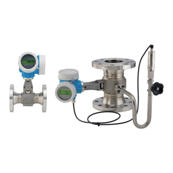
EF200R-C Product description Product description The device consists of a transmitter and a sensor. Two device versions are available: • Compact version ‒ transmitter and sensor form a mechanical unit. • Remote version - transmitter and sensor are mounted in separate locations. Product design A0020649 Important components of a measuring device Electronics compartment cover Display module Main electronics module Cable glands Transmitter housing (incl. HistoROM) I/O electronics module Terminals (spring loaded terminals, pluggable) Connection compartment cover Sensor A0034152 Versions of pressure measuring unit Order code for "Sensor version; DSC sensor; measuring tube", option "Mass steam" For order code for "Sensor version; DSC sensor; measuring tube", option "Mass steam" , the following applies : Oil-free or grease-free cleaning is not possible... -
Page 14: Incoming Acceptance And Product
Incoming acceptance and product identification EF200R-C Incoming acceptance and product identification Incoming acceptance Are the product sticker (1) idential? Are the goods undamaged? Is the envelope present with accompanying documents? • If one of the conditions is not satisfied, contact your TLV Sales Center. • Contact TLV for Technical Documentation. -
Page 15: Product Identification
EF200R-C Incoming acceptance and product identification Product identification The following options are available for identification of the device: • Nameplate specifications • Order code with breakdown of the device features on the delivery note For an overview of the scope of the associated Technical Documentation, refer to the following: 4.2.1 Transmitter nameplate (compact version) 4 A0032237 Name of the transmitter Model name Permitted fluid temperature Permitted ambient temperature Power supply voltage Degree of protection Serial number (ser. no.) -
Page 16: Sensor Nameplate (Remote Version)
Incoming acceptance and product identification EF200R-C 4.2.2 Sensor nameplate (remote version) Transmitter 4 Name of the transmitter Model name Permitted fluid temperature Permitted ambient temperature Power supply voltage Degree of protection Serial number (ser. no.) Sensor Name of the transmitter Model name Permitted fluid temperature Permitted ambient temperature Power supply voltage Degree of protection Serial number (ser. no.) -
Page 17: Nameplate For Teg
EF200R-C Incoming acceptance and product identification 4.2.3 Nameplate for TEG (compact version/remote version) VORTEX FLOWMETER EF 200-C Order code: O7F2C50-1234/56 IP66/67 Type 4X encl. Ser. no.: S201EA19000 Ext. ord. cd.: DC 9...32 V / 2-wire 4-20 mA HART Pulse/freq./switch output 4-20 mA Input 1x plug, 1x socket M12x1 T Ta + 20 K Ta: -20...+60 Profile: 3.02 V1.00.00 x Date: 2021-02 330820-0001B Name of the transmitter Model name Power supply voltage Electrical connection thread Permitted ambient temperature Degree of protection... -
Page 18: Storage And Transport
Storage and transport EF200R-C Storage and transport Storage conditions Observe the following notes for storage: ► Store in the original packaging to ensure protection from shock. ► Do not remove protective covers or protective caps installed on process connections. They prevent mechanical damage to the sealing surfaces and contamination in the measuring tube. ► Protect from direct sunlight to avoid unacceptably high surface temperatures. ► Store in a dry and dust-free place. ► Do not store outdoors. Storage temperature: ‒50 to +80 ˚C (‒58 to +176 ˚F ) Transporting the product Transport the measuring device to the measuring point in the original packaging. A0029252 Do not remove protective covers or caps installed on process connections. They prevent mechanical damage to the sealing surfaces and contamination in the measuring tube. 5.2.1 Measuring devices without lifting lugs WARNING Center of gravity of the measuring device is higher than the suspension points of the webbing slings. -
Page 19: Measuring Devices With Lifting Lugs
EF200R-C Storage and transport 5.2.2 Measuring devices with lifting lugs CAUTION Special transportation instructions for devices with lifting lugs ► Only use the lifting lugs fitted on the device or flanges to transport the device. ► The device must always be secured at two lifting lugs at least. -
Page 20: Mounting Position
Installation EF200R-C Installation Installation conditions 6.1.1 Mounting position Mounting location A0015543 Orientation The direction of the arrow on the sensor nameplate helps you to install the sensor according to the flow direction (direction of medium flow through the piping). Vortex meters require a fully developed flow profile as a prerequisite for correct volume flow measurement. Therefore, please note the following: Orientation Compact version Remote version 1) A Vertical orientation A0015545 2) 3) B Horizontal orientation, transmitter head up A0015589 4) 5) C Horizontal orientation, transmitter head down A0015590 4) D Horizontal orientation, transmitter head at side A0015592 In the case of liquids, there should be upward flow in vertical pipes to avoid partial pipe filling (Fig. A). Disruption in flow measurement! In the case of vertical orientation and downward flowing liquid, the pipe always needs to be completely filled to ensure correct liquid flow measurement. Danger of electronics overheating! If the fluid temperature is 200 ˚C (392 ˚F), orientation B is not permitted for the wafer version (EF200W-C) with nominal diameters of DN 100 (4") and DN 150 (6"). - Page 21 EF200R-C Installation Pressure measuring cell Steam pressure measurement Option DA • With the transmitter installed at the bottom or at the side • Protection against rising A0034057 heat • Reduction in temperature to almost ambient temperature due 1) to siphon A0034058 Note max. permitted ambient temperature of transmitter→ See 6.1.2 Minimum spacing and cable length Order code for "Sensor version", option "mass" A0019211 Minimum spacing in all directions Required cable length The following dimensions must be observed to guarantee problem-free access to the device for service purposes: • A =100 mm (3.94 in) •...
- Page 22 Installation EF200R-C 25 × DN × N 5 × DN 5 × DN 25 × DN 5 × DN 20 × DN 5 × DN 40 × DN 5 × DN 20 × DN 5 × DN 50 × DN 5 × DN 17 × DN + 8 × h 5 × DN h: Inner diameter difference 25 (1"): 40 (1½"): 5 × DN 40 × DN 5 ×...
- Page 23 EF200R-C Installation Flow conditioner If the inlet runs cannot be observed, the use of a flow conditioner is recommended. The flow conditioner is fitted between two pipe flanges and centered by the mounting bolts. Generally this reduces the inlet run needed to 10 × DN or 13 × DN with full accuracy. 5 × DN 8 × DN 5 × DN 2 × DN 8 × DN 5 × DN Flow Conditioner Flow Conditioner 5 × DN 8 × DN 5 × DN 2 × DN 8 × DN 5 × DN Flow Conditioner Flow Conditioner 2 × DN 8 × DN 5 × DN 5 ×...
- Page 24 Installation EF200R-C The pressure loss for flow conditioners is calculated as follows: p [mbar] = 0.0085 ρ ・ [kg/m [m/s] ・ Example for steam Example for H O condensate (80˚C) p = 10 bar abs. ρ = 965 kg/m t = 240 ˚C → ρ = 4.39 kg/m v = 2.5 m/s v = 40 m/s p = 0.0085 965 2.5 = 51.3 mbar ・ ・ p = 0.0085 4.394.39 = 59.7 mbar ・ ・ ρ : density of the process medium v: average flow velocity abs. = absolute For the dimensions of the flow conditioner, see the "Technical Information" document, "Mechanical construction" section Outlet runs when installing external devices If installing an external device, observe the specified distance.
-
Page 25: Environment And Process Requirements
EF200R-C Installation 6.1.2 Environment and process requirements Ambient temperature range Compact version Measuring device ‒40 to +80 ˚C (‒40 to +176˚F) ‒40 to +70 ˚C (‒40 to +158 ˚F) Local display At temperatures < ‒20 ˚C(‒4˚F ), depending on the physical characteristics involved, it may no longer be possible to read the liquid crystal display. Remote version Transmitter ‒40 to +80 ˚C (‒40 to +176 ˚F) ‒40 to +85 ˚C (‒40 to +185 ˚F) Sensor Local display ‒40 to +70 ˚C (‒40 to +158 ˚F) At temperatures < ‒20 ˚C(‒4˚F ), depending on the physical characteristics involved, it may no longer be possible to read the liquid crystal display. ► If operating outdoors: Avoid direct sunlight, particularly in warm climatic regions. You can order a weather protection cover from TLV. → See 15.1.1 Thermal insulation For optimum temperature measurement and mass calculation, heat transfer at the sensor must be avoided for some fluids. This can be ensured by installing thermal insulation. A wide range of materials can be used for the required insulation. -
Page 26: Ensuring Accurate Measurements
Installation EF200R-C max insulation height A0019212 Maximum insulation height ► When insulating, ensure that a sufficiently large area of the housing support remains exposed. The uncovered part serves as a radiator and protects the electronics from overheating and excessive cooling. Electronics overheating on account of thermal insulation! ► Observe the maximum permitted insulation height of the transmitter neck so that the transmitter head and/or the connection housing of the remote version is completely free. ► Observe information on the permissible temperature ranges. ► Note that a certain orientation might be required, depending on the fluid temperature. 6.1.3 Ensuring accurate measurements Installing the separator In some cases where steam is mixed with condensate, it may not be possible to obtain accurate flow rate measurements. To remove these causes for concern about flow rate measurements, it is recommended to install a separator upstream of the flowmeter. Wet steam Saturated steam のない with droplets without droplets 飽和 Flowmeter Separator... -
Page 27: Mounting The Measuring Device
EF200R-C Installation Mounting the measuring device 6.2.1 Required tools For transmitter • For turning the transmitter housing: Open-ended wrench8 mm • For opening the securing clamps: Allen key3 mm For sensor For flanges and other process connections: Corresponding mounting tools 6.2.2 Preparing the measuring device 1. Remove all remaining transport packaging. 2. Remove any protective covers or protective caps present from the sensor. 3. Remove stick-on label on the electronics compartment cover. 6.2.3 Mounting the sensor WARNING Danger due to improper process sealing! ► Ensure that the inside diameters of the gaskets are greater than or equal to that of the process connections and piping. ► Ensure that the gaskets are clean and undamaged. -
Page 28: Mounting The Pressure Measuring Unit
Installation EF200R-C 6.2.4 Mounting the pressure measuring unit Preparation 1. Prior to mounting the pressure measuring unit, install the measuring device in the pipe. 2. When mounting the pressure measuring unit, use only the seal provided. The use of a different sealing material is not permitted. Removing the blind flange 4 x 6 mm A0034355 Mounting screws blind flange Seal Flange connection on sensor side When replacing the seal following commissioning, fluid may escape when the flange connection is opened! ► Ensure that the measuring device is not under pressure. ► Ensure that there is no fluid in the measuring device. 1. Release the mounting screws on the blind flange. The screws are needed again to mount the pressure measuring unit. 2. Remove the internal seal. - Page 29 EF200R-C Installation Mounting the pressure measuring unit 4 x 6 mm A0035442 Siphon Pressure measuring cell Damage to seal! The seal is made of expanded graphite. It can therefore be used only once. If a coupling is released, a new seal must be installed. ► Use the additional seals provided. If necessary, these can be ordered as separate spare parts at a later stage. Insert the enclosed seal into the groove of the flange connection on the sensor side. 4. Align the flange connection on the pressure measuring unit and tighten the screws by hand. 5. Tighten the screws with a torque wrench in three steps. 1. 10 Nm in criss-cross sequence 2. 15 Nm in criss-cross sequence 3. 15 Nm in circular sequence...
-
Page 30: Mounting The Transmitter Of The Remote Version
Installation EF200R-C Connecting the pressure measuring unit A0035443 Device plug 6. Insert the plug for electrical connection of the pressure measuring cell and screw into place. 6.2.5 Mounting the transmitter of the remote version CAUTION Ambient temperature too high! Danger of electronics overheating and housing deformation. ► Do not exceed the permitted maximum ambient temperature . ► If operating outdoors: Avoid direct sunlight and exposure to weathering, particularly in warm climatic regions. CAUTION Excessive force can damage the housing! ► Avoid excessive mechanical stress. The transmitter of the remote version can be mounted in the following ways: • Wall mounting • Pipe mounting... -
Page 31: Turning The Transmitter Housing
EF200R-C Installation Wall mounting 19 (0.6) 80 (3.15) A0033484 mm (in) Post mounting 20 70 4 x SW 13 A0033486 mm (in) 6.2.6 Turning the transmitter housing To provide easier access to the connection compartment or display module, the transmitter housing can be turned. - Page 32 Installation EF200R-C max. 350° 8 mm 8 mm A0032242 1. Release the fixing screw. 2. Turn the housing to the desired position. 3. Firmly tighten the securing screw. 6.2.7 Turning the display module The display module can be turned to optimize display readability and operability. 3 mm A0032238 1. Loosen the securing clamp of the electronics compartment cover using an Allen key. 2. Unscrew cover of the electronics compartment from the transmitter housing. 3. Optional: pull out the display module with a gentle rotational movement. 4. Turn the display module to the desired position: max. 8 × 45° in every direction. 5. Without display module pulled out: Allow display module to engage at desired position. 6. With display module pulled out: Feed the cable into the gap between the housing and main electronics module and plug the display module into the electronics compartment until it engages. 7. Reverse the removal procedure to reassemble the transmitter.
-
Page 33: Post-Installation Check
EF200R-C Installation Post-installation check Is the device undamaged (visual inspection)? ▢ Does the measuring device conform to the measuring point specifications? For example: • Process temperature → See 16.9 ▢ • Process pressure (refer to the section on "Pressure-temperature ratings" in the "Technical Information" document → See 16.15) • Ambient temperature • Measuring range → See 16.3 Has the correct orientation for the sensor been selected? → See 6.1.1 • According to sensor type ▢ • According to medium temperature • According to medium properties (outgassing, with entrained solids) Does the arrow on the sensor nameplate match the direction of flow of the fluid through the ▢ piping? → See 6.1.1 Are the measuring point identification and labeling correct (visual inspection)? ▢ Is the device adequately protected against precipitation and direct sunlight? ▢ Are the securing screw and securing clamp tightened securely? ▢ Has the maximum permitted insulation height been observed? ▢ • Has the pressure range been observed? → See 16.9 • Was the correct orientation selected? → See 6.1.1 •... -
Page 34: Electrical Connection Connection Conditions
Electrical connection EF200R-C Electrical connection Connection conditions 7.1.1 Required tools • For cable entries: Use corresponding tools • For securing clamp: Allen key 3 mm • Wire stripper • When using stranded cables: Crimper for wire end ferrule • For removing cables from terminal: Flat blade screwdriver 3 mm (0.12 in) 7.1.2 Connecting cable requirements The connecting cables provided by the customer must fulfill the following requirements. Electrical safety In accordance with applicable federal/national regulations. Permitted temperature range • The installation guidelines that apply in the country of installation must be observed. • The cables must be suitable for the minimum and maximum temperatures to be expected. Signal cable Current output 4 to 20 mA A shielded cable is recommended. Observe grounding concept of the plant. -
Page 35: Connecting Cable For Remote Version
EF200R-C Electrical connection 7.1.3 Connecting cable for remote version Connecting cable Standard cable 2 × 2 × 0.5 mm (22 AWG) PVC cable with common shield (2 pairs, pair- stranded) Flame resistance According to DIN EN 60332-1-2 Oil-resistance According to DIN EN 60811-2-1 Shielding Galvanized copper-braid, opt. density approx.85 % Cable length 30 m (98 ft) Operating temperature When mounted in a fixed position: ‒50 to +105˚C (‒58 to +221˚F); when cable can move freely: ‒25 to +105˚C (‒13 to +221˚F) UV radiation may cause damage to the outer jacket of the cable. Protect the cable from exposure to sun as much as possible. Connecting cable (option "mass pressure-/temperature-compensated") Order code for "Sensor version; DSC sensor; measuring tube" Standard cable [(3 × 2) + 1] × 0.34 mm (22 AWG)PVC cable with common shield (3 pairs, pair- stranded) Flame resistance According to DIN EN 60332-1-2... -
Page 36: Terminal Assignment
Electrical connection EF200R-C 7.1.4 Terminal assignment Transmitter 4-20 mA HART connection version with additional inputs and outputs ‒ ‒ A0033475 Maximum number of terminals Terminals 1 to 4: Without integrated overvoltage protection Output 1 (passive): supply voltage and signal transmission Output 2 (passive): supply voltage and signal transmission Ground terminal for cable shield Terminal numbers Output 1 Output 2 1 (+) 2 (-) 3 (+) 4 (-) Pulse/frequency/switch 4-20 mA HART (passive) output (passive) Output 1 must always be used; output 2 is optional. Connecting cable for remote version Transmitter and sensor connection housing In the case of the remote version, the sensor and transmitter are mounted separately from on another and connected by a connecting cable. Connection is performed via the sensor connection housing and the transmitter housing. Use of connecting cable Terminals are always used to connect the connecting cable in the sensor connection housing (tightening torques for screws for cable strain relief: 1.2 to 1.7 Nm). Connecting cable (standard, reinforced) ‒... - Page 37 EF200R-C Electrical connection Terminal number Assignment Cable color Connecting cable Supply voltage Brown Grounding White RS485 (+) Yellow RS485 (‒) Green Connecting cable (option "mass pressure-/temperature-compensated") Order code for "Sensor version; DSC sensor; measuring tube", option ‒ ‒ BK YE BU ‒ ‒ A0034571 Terminals for connection compartment in the transmitter wall holder and the sensor connection housing Terminals for connecting cable Grounding via the cable strain relief Terminal number Assignment Cable color Connecting cable RS485 (-) DPC Brown RS485 (+) DPC White Reset Green Supply voltage Grounding Black RS485 (+)
-
Page 38: Requirements For The Supply Unit
Electrical connection EF200R-C 7.1.5 Requirements for the supply unit Supply voltage Transmitter An external power supply is required for each output. The following supply voltage values apply for the outputs available: Load Load for current output: 0 to 500 Ω, depending on the external supply voltage of the power supply unit Calculation of the maximum load Depending on the supply voltage of the power supply unit (U ), the maximum load (R including line resistance must be observed to ensure adequate terminal voltage at the device. In doing so, observe the minimum terminal voltage • For U = 17.9 to 18.9 V: R (U - 17.9 V): 0.0036 A B • For U = 18.9 to 24 V: R (U - 13 V): 0.022 A B • For U = 24 V: R 500 Ω... -
Page 39: Connecting The Measuring Device
EF200R-C Electrical connection [Ω] U [V] A0013563 Operating range Sample calculation Supply voltage of power supply unit: U =19 V Maximum load: R (19 V - 13 V): 0.022 A = 273 Ω B 7.1.6 Preparing the measuring device Carry out the steps in the following order: 1. Mount the sensor and transmitter. 2. Connection housing, sensor: Connect connecting cable. 3. Transmitter: Connect connecting cable. 4. Transmitter: Connect signal cable and cable for supply voltage. Insufficient sealing of the housing! Operational reliability of the measuring device could be compromised. ► Use suitable cable glands corresponding to the degree of protection. 1. Remove dummy plug if present. 2. If the measuring device is supplied without cable glands: Provide suitable cable gland for corresponding connecting cable. 3. If the measuring device is supplied with cable glands: Observe requirements for connecting cables → See 7.1.2 Connecting the measuring device Limitation of electrical safety due to incorrect connection! -
Page 40: Connecting The Compact Version
Electrical connection EF200R-C 7.2.1 Connecting the compact version Connecting the transmitter Connection via terminals 3 mm 20 mm 10 (0.4) mm (in) A0032239 1. Loosen the securing clamp of the connection compartment cover. 2. Unscrew the connection compartment cover. 3. Push the cable through the cable entry . To ensure tight sealing, do not remove the sealing ring from the cable entry. 4. Strip the cable and cable ends. In the case of stranded cables, also fit ferrules. 5. Connect cable in accordance with terminal assignment → See 7.1.4. when connecting the cable shielding to the ground clamp, observe the grounding concept of the facility. WARNING Housing degree of protection may be voided due to insufficient sealing of the housing. ► Screw in the screw without using any lubricant. The threads on the cover are coated with a dry lubricant. Firmly tighten the cable glands. 7. Reverse the removal procedure to reassemble the transmitter. - Page 41 EF200R-C Electrical connection Removing a cable 3 (0.12) A0032240 ► To remove a cable from the terminal, use a flat-blade screwdriver to push the slot between the two terminal holes while simultaneously pulling the cable end out of the terminal. 7.2.2 Connecting the remote version WARNING Risk of damaging the electronic components! ► Connect the sensor and transmitter to the same potential equalization. ► Only connect the sensor to a transmitter with the same serial number. The following procedure (in the action sequence given) is recommended for the remote version: 1. Mount the sensor and transmitter. 2. Connect the connecting cable for the remote version. 3. Connect the transmitter. Use of connecting cable Terminals are always used to connect the connecting cable in the sensor connection housing (tightening torques for screws for cable strain relief: 1.2 to 1.7 Nm).
- Page 42 Electrical connection EF200R-C Connecting the sensor connection housing 3 mm A0034167 1. Loosen the securing clamp. 2. Unscrew the housing cover. A0034171 Sample graphic Connecting cable 3. Guide the connecting cable through the cable entry and into the connection housing (if using a connecting cable without an M12 device plug, use the shorter stripped end of the connecting cable). 4. Wire the connecting cable: Terminal 1 = brown cable Terminal 2 = white cable Terminal 3 = yellow cable Terminal 4 = green cable 5. Connect the cable shield via the cable strain relief. 6. Tighten the screws for the cable strain relief using a torque in the range of 1.2 to 1.7 Nm. 7. Reverse the removal procedure to reassemble the connection housing. Connecting cable (option "mass pressure-/temperature-compensated") 3. Guide the connecting cable through the cable entry and into the connection housing (if using a connecting cable without an M12 device plug, use the shorter stripped end of the connecting cable).
- Page 43 EF200R-C Electrical connection 4. Wire the connecting cable: Terminal 1 = brown cable Terminal 2 = white cable Terminal 3 = green cable Terminal 4 = red cable Terminal 5 = black cable Terminal 6 = yellow cable Terminal 7 = blue cable 5. Connect the cable shield via the cable strain relief. 6. Tighten the screws for the cable strain relief using a torque in the range of 1.2 to 1.7 Nm. 7. Reverse the removal procedure to reassemble the connection housing. Connecting transmitter via terminals 3 mm A0034173 1. Loosen the securing clamp of the electronics compartment cover. 2. Unscrew the electronics compartment cover. 3. Pull out the display module with a gentle rotational movement. To make it easier to access the lock switch, attach the display module to the edge of the electronics compartment. TX 10 8 mm A0034174 4. Loosen the locking screw of the transmitter housing. 5. Loosen the securing clamp of the transmitter housing.
- Page 44 Electrical connection EF200R-C ~15° A0034175 Sample graphic 6. Turn the transmitter housing to the right until it reaches the marking. The connection board of the wall housing is connected to the electronics board of the transmitter via a signal cable! ► Pay attention to the signal cable when lifting the transmitter housing! Lift the transmitter housing. A0034176 Sample graphic A0034177 Sample graphic...
- Page 45 EF200R-C Electrical connection Connecting cable 8. Disconnect the signal cable from the connection board of the wall housing by pressing in the locking clip on the connector. Remove the transmitter housing. 9. Guide the connecting cable through the cable entry and into the connection housing (if using a connecting cable without an M12 device plug, use the shorter stripped end of the connecting cable). 10. Wire the connecting cable: Terminal 1 = brown cable Terminal 2 = white cable Terminal 3 = yellow cable Terminal 4 = green cable 11. Connect the cable shield via the cable strain relief. 12. Tighten the screws for the cable strain relief using a torque in the range of 1.2 to 1.7 Nm. 13. Reverse the removal procedure to reassemble the transmitter housing. Cable strain relief...
-
Page 46: Connecting The Connecting Cable For The Pressure Measuring Cell
Electrical connection EF200R-C 7.2.3 Connecting the connecting cable for the pressure measuring cell When delivered to the customer, the connecting cable is connected as follows: • Compact version: to transmitter housing • Remote version: to sensor connection housing For connection to sensor and pressure measuring cell: ► Insert M12 plug of connecting cable into pressure measuring cell and screw into place. 7.2.4 Ensuring potential equalization Requirements Please consider the following to ensure correct measurement: • Same electrical potential for the fluid and sensor • Remote version: same electrical potential for the sensor and transmitter • Company-internal grounding concepts • Pipe material and grounding Ensuring the degree of protection The measuring device fulfills all the requirements for the IP66/67 degree of protection, Type 4X enclosure. -
Page 47: Post-Connection Check
EF200R-C Electrical connection Post-connection check Are cables or the device undamaged (visual inspection)? ▢ Do the cables used meet the requirements? → See 7.1.2 ▢ Do the mounted cables have adequate strain relief? ▢ Are all cable glands installed, securely tightened and leak-tight? Cable run with "water trap"? ▢ → See 7.3 Depending on the device version, are all the device plugs firmly tightened?→ See 7.2 ▢ Only for remote version: is the sensor connected to the right transmitter? ▢ Check the serial number on the nameplate of the sensor and transmitter. Does the supply voltage match the specifications on the transmitter nameplate? ▢ Is the terminal assignment correct? ▢ If supply voltage is present, do values appear on the display module? ▢ Are all the housing covers installed and tightened? ▢ Is the securing clamp tightened correctly? ▢ Have the screws for the cable strain relief been tightened using the correct torque? → See 7.2.2 ▢ Has the M12 plug of the connecting cable been correctly connected to the pressure measuring ▢ cell? → See 7.2.2... -
Page 48: 7.5 Connecting To Tlv Ec351 Flow Computer
Electrical connection EF200R-C 7.5 Connecting to TLV EC351 Flow Computer This device can be used in combination with the flow indicator EC351. The correct- ed flow rate of fluids whose temperature and pressure change (superheated steam, air) can be displayed by combining with EC351 and a pressure sensor. As for the connection with this device, the output and signal are associated as follows as standard. EF200R-C Settings • Analog output: Temperature (Current output settingas → See 10.4.5) • Pulse output: (pulse/frequency/switch output settings → See 10.4.6) Assign pulse output 1: Pulse output: Mass flowrate (pulse output settings → See 10.4.6 Value per pulse: Set the specified values in the table below according to the size of the device. Size Value per pulse 0.0684 0.3478 0.8551 1.4258 3.1995 5.5420 12.6070 Pulse width: 5 ms • Volume unit: L (litre) or dm3 (system units settings → See 10.4.2) EC351 Settings •... -
Page 49: Operation Options
EF200R-C Operation options Operation options Overview of operation options A0032226 Local operation via display module Computer with operating tool Field Xpert SFX350 or SFX370 Field Communicator 475 Control system (e.g. PLC) VIATOR Bluetooth modem with connecting cable... - Page 50 Operation options EF200R-C Structure and function of the operating menu 8.2.1 Structure of the operating menu For an overview of the operating menu for experts: "Description of Device Parameters" document supplied with the device Operating menu for operators and maintenances Language Operatation Language Parameter 1 Parameter n Submenu 1 Submenu n Setup Device tag Wizard 1 / Parameter 1 Wizard n / Parameter n Advanced setup Enter access code Parameter 1 Parameter n Submenu 1 Submenu n Diagnostics Parameter 1 Parameter n Submenu 1 Submenu n Operating menu for experts...
-
Page 51: Operating Philosophy
EF200R-C Operation options 8.2.2 Operating philosophy The individual parts of the operating menu are assigned to certain user roles (operator, maintenance etc.). Each user role contains typical tasks within the device lifecycle. Menu/parameter User role and tasks Content/meaning Language task-oriented Role "Operator", "Maintenance" • Defining the operating language Tasks during operation: • Configuring the operational display Operation • Configuring the operational display (e.g. display format, display contrast) • Reading measured values • Resetting and controlling totalizers Setup "Maintenance" role Wizards for fast commissioning: Commissioning: • Setting the system units • Configuration of the measurement • Defining the medium • Configuration of the inputs and • Configuring the current input outputs •... -
Page 52: Access To The Operating Menu Via The Local
Operation options EF200R-C Access to the operating menu via the local display 8.3.1 Operational display X X X X X X X 1120.50 A0029346 Operational display Device tag→ See 10.4.1 Status area Display area for measured values (4-line) Operating elements→ See 8.3.4 Status area The following symbols appear in the status area of the operational display at the top right: • Status signals→ See 12.2.1 • F: Failure • C: Function check • S: Out of specification • M: Maintenance required •... - Page 53 EF200R-C Operation options Totalizer The measurement channel number indicates which of the three totalizers is displayed. Output The measurement channel number indicates which of the two current outputs is displayed. Measurement channel numbers Symbol Meaning Measurement channel 1 to 4 The measurement channel number is displayed only if more than one channel is present for the same measured variable type (e.g. Totalizer 1 to 3). Diagnostic behavior The diagnostic behavior pertains to a diagnostic event that is relevant to the displayed measured variable. For information on the symbols → See 12.2.1 The number and display format of the measured values can be configured via the Format display parameter (→ See 10.4.7). 8.3.2 Navigation view In the submenu In the wizard /../Curr. output 1 /../Operation 0091-1 Assign curr. Access stat.disp Volume flow Operator Locking status Display A0013993-EN A0016327-EN Navigation view Navigation path to current position Status area...
- Page 54 Operation options EF200R-C For more information about the icons in the menu, refer to the "Display area" section → See 8.3.1 Status area The following appears in the status area of the navigation view in the top right corner: • In the submenu • The direct access code for the parameter you are navigating to (e.g. 0022-1) • If a diagnostic event is present, the diagnostic behavior and status signal • In the wizard If a diagnostic event is present, the diagnostic behavior and status signal • For information on the diagnostic behavior and status signal → See 12.2.1 • For information on the function and entry of the direct access code → See 8.3.6 Display area Menus Symbol Meaning Operation Appears: • In the menu next to the "Operation" selection • At the left in the navigation path in the Operation menu Setup Appears: • In the menu next to the "Setup" selection • At the left in the navigation path in the Setup menu Diagnostics Appears: • In the menu next to the "Diagnostics" selection •...
- Page 55 EF200R-C Operation options Wizard operation Symbol Meaning Switches to the previous parameter. Confirms the parameter value and switches to the next parameter. Opens the editing view of the parameter. 8.3.3 Editing view Numeric editor Text editor User ABC̲ DEFG HIJK LMNO PQRS TUVW A0013999 A0013941 Editing view Display area of the entered values Input mask Operating elements → See 8.3.4 Input mask The following input symbols are available in the input mask of the numeric and text editor: Numeric editor Symbol Meaning Selection of numbers from 0 to 9. … Inserts decimal separator at the input position. Inserts minus sign at the input position. ‒ Confirms selection.
- Page 56 Operation options EF200R-C Text editor Symbol Meaning Toggle • Between upper-case and lower-case letters • For entering numbers • For entering special characters Selection of letters from A to Z. ABC ̲ … Selection of letters from a to z. abc ̲ … "'^ ̲ Selection of special characters. … ̲ ~& Confirms selection. Switches to the selection of the correction tools. Exits the input without applying the changes. Clears all entered characters. Correction symbols under Symbol Meaning Clears all entered characters. Moves the input position one position to the right. Moves the input position one position to the left. Deletes one character immediately to the left of the input position.
-
Page 57: Operating Elements
EF200R-C Operation options 8.3.4 Operating elements Operating key(s) Meaning Minus key In a menu, submenu Moves the selection bar upwards in a picklist. With a Wizard Confirms the parameter value and goes to the previous parameter. With a text and numeric editor In the input screen, moves the selection bar to the left (backwards). Plus key In a menu, submenu Moves the selection bar downwards in a picklist. With a Wizard Confirms the parameter value and goes to the next parameter. With a text and numeric editor Moves the selection bar to the right (forwards) in an input screen. Enter key For operational display Pressing the key for 2 s opens the context menu. In a menu, submenu • Pressing the key briefly: • Opens the selected menu, submenu or parameter. • Starts the wizard. • If help text is open, closes the help text of the parameter. • Pressing the key for 2 s for parameter: If present, opens the help text for the function of the parameter. With a Wizard Opens the editing view of the parameter. With a text and numeric editor • Pressing the key briefly: •... - Page 58 Operation options EF200R-C Calling up and closing the context menu The user is in the operational display. 1. Press the and keys for longer than 3 seconds. The context menu opens. XXXXXXXXXX Setup Conf.backup disp Simulation Keylock on A0034284-EN 2. Press + simultaneously. The context menu is closed and the operational display appears. Calling up the menu via the context menu 1. Open the context menu. 2. Press to navigate to the desired menu. 3. Press to confirm the selection. The selected menu opens.
-
Page 59: Navigating And Selecting From List
EF200R-C Operation options 8.3.6 Navigating and selecting from list Different operating elements are used to navigate through the operating menu. The navigation path is displayed on the left in the header. Icons are displayed in front of the individual menus. These icons are also shown in the header during navigation. For an explanation of the navigation view with symbols and operating elements → See 8.3.2 Example: Setting the number of displayed measured values to "2 values" X X X X X X X 20.50 0104-1 Main menu Language English Display/operat. Setup Main menu Language Display/operat. - Page 60 Operation options EF200R-C The direct access code consists of a 5-digit number (at maximum) and the channel number, which identifies the channel of a process variable: e.g. 00914-2. In the navigation view, this appears on the right-hand side in the header of the selected parameter. 00914-2 A0029414 Direct access code Note the following when entering the direct access code: • The leading zeros in the direct access code do not have to be entered. Example: Enter " 914" instead of " 00914" • If no channel number is entered, channel 1 is accessed automatically. Example: Enter 0 0914 → A ssign process variable parameter • If a different channel is accessed: Enter the direct access code with the corresponding channel number. Example: Enter 0 0914-2 → A ssign process variable parameter For the direct access codes of the individual parameters, see the "Description of Device Parameters" document for the device 8.3.8 Calling up help text Help text is available for some parameters and can be called up from the navigation view.
-
Page 61: Changing The Parameters
EF200R-C Operation options 8.3.9 Changing the parameters For a description of the editing view - consisting of the text editor and numeric editor - with symbols → See 8.3.3, for a description of the operating elements → See 8.3.4 Example: Changing the tag name in the "Tag description" parameter from 001-FT-101 to 001-FT-102 /../Advanced setup 1496-1 001-FT-101 Ent. access code DEFG HIJK Tag description LMNO PQRS TUVW 001-FT-101 Def. access code 001-FT-101 001-FT-101 DEFG HIJK DEFG HIJK LMNO PQRS TUVW 001-FT-10 DEFG HIJK 001-FT-10 001-FT-10 DEFG HIJK DEFG HIJK... -
Page 62: User Roles And Related Access Authorization
Operation options EF200R-C value Min:0 Max:9999 A0014049-EN 8.3.10 User roles and related access authorization The two user roles "Operator" and "Maintenance" have different write access to the parameters if the customer defines a user-specific access code. This protects the device configuration via the local display from unauthorized access . Defining access authorization for user roles An access code is not yet defined when the device is delivered from the factory. Access authorization (read and write access) to the device is not restricted and corresponds to the "Maintenance" user role. ► Define the access code. The "Operator" user role is redefined in addition to the "Maintenance" user role. Access authorization differs for the two user roles. Access authorization to parameters: "Maintenance" user role Access code status Read access Write access An access code has not yet been defined (factory setting). -
Page 63: Enabling And Disabling The Keypad Lock
EF200R-C Operation options 8.3.12 Enabling and disabling the keypad lock The keypad lock makes it possible to block access to the entire operating menu via local operation. As a result, it is no longer possible to navigate through the operating menu or change the values of individual parameters. Users can only read the measured values on the operational display. The keypad lock is switched on and off via the context menu. To activate the keylock manually: 1. The device is in the measured value display. Press the and keys for 3 seconds. A context menu appears. 2. In the context menu select the Keylock on option. The keypad lock is switched on. If the user attempts to access the operating menu while the keypad lock is active, the Keylock on message appears. Switching off the keypad lock ► The keypad lock is switched on. Press the and keys for 3 seconds. The keypad lock is switched off. Access to the operating menu via the operating tool The structure of the operating menu in the operating tools is the same as for operation... - Page 64 Operation options EF200R-C A0028746 Options for remote operation via HART protocol (passive) Control system (e.g. PLC) Transmitter power supply unit, e.g. RN221N (with communication resistor) Connection for Commubox FXA195 and Field Communicator 475 Field Communicator 475 Computer with web browser (e.g. Internet Explorer) for accessing computers with operating tool (e.g. FieldCare, DeviceCare, AMS Device Manager, SIMATIC PDM) with COM DTM "CDI Communication TCP/IP" Commubox FXA195 (USB) Field Xpert SFX350 or SFX370 VIATOR Bluetooth modem with connecting cable Transmitter...
-
Page 65: System Integration
EF200R-C System integration System integration Overview of device description files 9.1.1 Current version data for the device Firmware version 01.03.00 • On the title page of the Operating Instructions • On the transmitter nameplate • Firmware version parameter Diagnostics → Device information → Firmware version Release date of firmware version 01.2018 Manufacturer ID 0x11 Manufacturer ID parameter Diagnostics → Device information → Manufacturer ID Device type ID 0x38 Device type parameter Diagnostics → Device information → Device type HART protocol revision Device revision •... -
Page 66: Commissioning
Commissioning EF200R-C Commissioning 10.1 Function check Before commissioning the measuring device: ► Make sure that the post-installation and post-connection checks have been performed. • "Post-installation check" checklist → See 6.3 • "Post-connection check" checklist → See 7.4 10.2 Switching on the measuring device ► After a successful function check, switch on the measuring device. After a successful startup, the local display switches automatically from the startup display to the operational display. If nothing appears on the local display or a diagnostic message is displayed, refer to the section on "Diagnostics and troubleshooting" → See 12.1 10.3 Setting the operating language Factory setting: English or ordered local language X X X X X X X 20.50 Main menu 0104-1 Display language... -
Page 67: Configuring The Measuring Device
EF200R-C Commissioning 10.4 Configuring the measuring device • The Setup menu with its guided wizards contains all the parameters needed for standard operation. • Navigation to the S etup menu X X X X X X X 20.50 Main menu 0104-1 Language English Operation Setup Main menu Operation Setup Diagnostic / ../Setup Medium selection XXXXXXXXX XXXXXXXXX A0034189-EN Taking the example of the local display Setup Device tag... -
Page 68: Defining The Tag Name
Commissioning EF200R-C 10.4.1 Defining the tag name To enable fast identification of the measuring point within the system, you can enter a unique designation using the Device tag parameter and thus change the factory setting. XXXXXXXXX A0029422 Header of the operational display with tag name Tag name Enter the tag name in the "FieldCare" operating tool Navigation "Setup" menu → Device tag Parameter overview with brief description Parameter Description User entry Factory setting Device tag Enter the name for the measuring point. Max. 32 characters, such as Prowirl letters, numbers or special characters (e.g. @, %, /). 10.4.2 Setting the system units In the System units submenu the units of all the measured values can be set. The number of submenus and parameters can vary depending on the device version. Certain submenus and parameters in these submenus are not described in the Operation Instructions. Instead a description is provided in the Special Documentation for the device (→ "Supplementary documentation" section). - Page 69 EF200R-C Commissioning Energy flow unit Energy unit Calorific value unit Calorific value unit Velocity unit Density unit Specific volume unit Dynamic viscosity unit Length unit Parameter overview with brief description Parameter Prerequisite Description Selection Factory setting Volume flow unit ‒ Select volume flow unit. Unit choose list Country-specific: • m³/h Result • ft³/min The selected unit applies for: • Output • Low flow cut off • Simulation process variable Volume unit ‒...
- Page 70 Commissioning EF200R-C Parameter Prerequisite Description Selection Factory setting Pressure unit Select process pressure unit. Unit choose list Country-specific: • bar Result • psi The unit is taken from: • Calculated saturated steam pressure • Atmospheric pressure • Maximum value • Fixed process pressure • Pressure • Reference pressure Temperature unit ‒ Select temperature unit. Unit choose list Country-specific: • °C Result • °F The selected unit applies for:...
- Page 71 EF200R-C Commissioning Parameter Prerequisite Description Selection Factory setting Calorific value unit (Mass) • The Gross calorific value Select calorific value unit. Unit choose list Country-specific: mass option or the Net • kJ/kg calorific value mass option • Btu/lb is selected in the Calorific value type parameter. Velocity unit ‒ Select velocity unit. Unit choose list Country-specific: • m/s Result • ft/s The selected unit applies for: • Flow velocity • Maximum value Density unit...
-
Page 72: Selecting And Setting The Medium
Commissioning EF200R-C 10.4.3 Selecting and setting the medium The Medium selection wizard systematically guides the user through all the parameters that must be configured in order to select and set the medium. Navigation "Setup" menu → Medium selection ► Medium selection Select medium Select gas type Gas type Relative humidity Steam calculation mode Select liquid type Fixed process pressure Enthalpy calculation Density calculation Enthalpy type This product is intended for use with steam, water and air. Parameter overview with brief description Parameter Prerequisite Description Selection / User Factory setting entry Select medium ‒ Select medium type. • Gas Steam •... - Page 73 EF200R-C Commissioning Parameter Prerequisite Description Selection / User Factory setting entry Gas type The following conditions are Select measured gas type. • Hydrogen H2 Methane CH4 met: • Helium He • In the Select medium • Neon Ne parameter, the G as option is • Argon Ar selected. • Krypton Kr • In the Select gas type • Xenon Xe parameter, the S ingle gas • Nitrogen N2 option is selected.
- Page 74 Commissioning EF200R-C Parameter Prerequisite Description Selection / User Factory setting entry Select liquid type The following conditions are Select measured liquid type. • Water Water met: • LPG (Liquefied • Order code for "Sensor Petroleum Gas) version", • User-specific liquid • Option "Mass (integrated temperature measurement)" • Option "Mass (integrated pressure/temperature measurement)" • The Liquid option is selected in the Select medium parameter parameter. Fixed process pressure The following conditions are Enter fixed value for process...
-
Page 75: Configuring The Current Input
EF200R-C Commissioning Parameter Prerequisite Description Selection / User Factory setting entry Density calculation The following conditions are Select the norm the density • AGA Nx19 AGA Nx19 met: calculation is based on. • ISO 12213- 2 • In the Select medium • ISO 12213- 3 parameter, the G as option is selected. • In the Select gas type parameter, the N atural gas option is selected. Enthalpy type The following conditions are Define which kind of enthalpy • Heat Heat met: is used. -
Page 76: Configuring The Current Output
Commissioning EF200R-C 10.4.5 Configuring the current output The Current output wizard guides you systematically through all the parameters that have to be set for configuring the current output. Navigation "Setup" menu → Current output 1 ► Current output 1 Assign current output 1 Current span 4 mA value 20 mA value Fixed current Damping output 1 Failure mode Failure current Parameter overview with brief description Parameter Prerequisite Description Selection / User Factory setting entry Assign current output ‒ Select process variable for • Off Volume flow current output. • Volume flow •... - Page 77 EF200R-C Commissioning Parameter Prerequisite Description Selection / User Factory setting entry 20 mA value One of the following options is Enter 20 mA value. Signed floating-point Depends on country selected in the Current span number and nominal parameter : diameter • 4...20 mA NAMUR • 4...20 mA US • 4...20 mA Fixed current The Fixed current option is Defines the fixed output 3.59 to 22.5 mA 4 mA selected in the Current span current. parameter . Damping output 1 ‒ Set the reaction time of the 0 to 999.9 s 1 s output signal of the current output to fluctuations in the...
-
Page 78: Configuring The Pulse/Frequency/Switch Output
Commissioning EF200R-C 10.4.6 Configuring the pulse/frequency/switch output The Pulse/frequency/switch output wizard guides you systematically through all the parameters that can be set for configuring the selected output type. Navigation "Setup" menu → Pulse/frequency/switch output Pulse/frequency/switch output Operating mode Parameter overview with brief description Parameter Description Selection Factory setting Operating mode Define the output as a pulse, frequency or • Pulse Pulse switch output. • Frequency • Switch Configuring the pulse output Navigation "Setup" menu → Pulse/frequency/switch output Pulse/frequency/switch output Assign pulse output 1 Value per pulse... - Page 79 EF200R-C Commissioning Parameter overview with brief description Parameter Prerequisite Description Selection / User Factory setting entry Assign pulse output 1 The Pulse option is selected in Select process variable for • Off Volume flow the Operating mode pulse output. • Volume flow parameter parameter. • Corrected volume flow • Mass flow * • Total mass flow * • Energy flow • Heat flow * difference Value per pulse The Pulse option is selected in...
- Page 80 Commissioning EF200R-C Failure mode Failure frequency Invert output signal Parameter overview with brief description Parameter Prerequisite Description Selection / User Factory setting entry Assign frequency output The Frequency option is Select process variable for • Off Off selected in the Operating mode frequency output. • Volume flow parameter (→ See 10.4.6). • Corrected volume flow • Mass flow • Flow velocity • Temperature • Pressure • Calculated saturated steam...
- Page 81 EF200R-C Commissioning Parameter Prerequisite Description Selection / User Factory setting entry Failure frequency The Frequency option is Enter frequency output value 0.0 to 1 250.0 Hz 0.0 Hz selected in the Operating in alarm condition. mode parameter and a process variable is selected in the Assign frequency output parameter. Invert output signal ‒ Invert the output signal. • No • Yes Visibility depends on order options or device settings Configuring the switch output Navigation "Setup" menu → Pulse/frequency/switch output Pulse/frequency/switch output Switch output function Assign diagnostic behavior Assign limit Assign status Switch-on value...
- Page 82 Commissioning EF200R-C Parameter overview with brief description Parameter Prerequisite Description Selection / User Factory setting entry Switch output function The Switch option is selected Select function for switch • Off Off in the Operating mode output. • On parameter. • Diagnostic behavior • Limit • Status Assign diagnostic behavior • In the Operating mode Select diagnostic behavior for • Alarm Alarm parameter, the S witch switch output.
-
Page 83: Configuring The Local Display
EF200R-C Commissioning Parameter Prerequisite Description Selection / User Factory setting entry Switch-off delay • The Switch option is Define delay for the switch-off 0.0 to 100.0 s 0.0 s selected in the Operating of status output. mode parameter. • The Limit option is selected in the Switch output function parameter. Failure mode ‒ Define output behavior in • Actual status Open alarm condition. • Open • Closed Invert output signal ** ‒ Invert the output signal. • No • Yes Visibility depends on order options or device settings... - Page 84 Commissioning EF200R-C Parameter overview with brief description Parameter Prerequisite Description Selection / User Factory setting entry Format display A local display is provided. Select how measured values • 1 value, max. size 1 value, max. size are shown on the display. • 1 bargraph + 1 value • 2 values • 1 value large + 2 values • 4 values Value 1 display A local display is provided. Select the measured value that • Volume flow Volume flow is shown on the local display. • Corrected volume flow •...
-
Page 85: Configuring The Low Flow Cut Off
EF200R-C Commissioning 10.4.8 Configuring the low flow cut off The Low flow cut off wizard systematically guides the user through all the parameters that must be set to configure low flow cut off. The measuring signal must have a certain minimum signal amplitude so that the signals can be evaluated without any errors. Using the nominal diameter, the corresponding flow can also be derived from this amplitude. The minimum signal amplitude depends on the setting for the sensitivity of the DSC sensor (s), the steam quality (x) and the force of the vibrations present (a). The value mf corresponds to the lowest measurable flow velocity without vibration (no wet steam) at a density of 1 kg/m (0.0624 lbm/ft^3). The value mf can be set in the range from 6 to 20 m/s (1.8 to 6 ft/s) (factory setting 12 m/s (3.7 ft/s)) with the Sensitivity parameter (value range 1 to 9, factory setting 5). The lowest flow velocity that can be measured on account of the signal amplitude v AmpMin is derived from the Sensitivity parameter and the steam quality (x) or from the force of vibrations present (a). Navigation "Setup" menu → Low flow cut off ► Low flow cut off Sensitivity Turn down Parameter overview with brief description Parameter Description User entry Factory setting... -
Page 86: Advanced Settings
Commissioning EF200R-C 10.5 Advanced settings The Advanced setup submenu together with its submenus contains parameters for specific settings. Navigation to the "Advanced setup" submenu X X X X X X X 20.50 0104-1 Main menu Language English Operatation Setup Main menu Operatation Setup Diagnostic / ../Setup Medium selection XXXXXXXXX XXXXXXXXX / ../Setup XXXXXXXXX XXXXXXXXX Advanced setup / ../Advanced setup 0092-1 Ent. access code **** Device tag Def. access code A0034208-EN... -
Page 87: Setting The Medium Properties
EF200R-C Commissioning ► SIL confirmation ► Deactivate SIL ► Display → See 10.5.5 ► Heartbeat setup ► Configuration backup display → See 10.5.6 ► Administration → See 10.5.7 10.5.1 Setting the medium properties In the Medium properties submenu the reference values for the measuring application can be set. Navigation "Setup" menu → Advanced setup → Medium properties ► Medium properties Enthalpy type Calorific value type Reference combustion temperature Reference density Reference gross calorific value Reference pressure Reference temperature Reference Z-factor Linear expansion coefficient Relative density Specific heat capacity Calorific value Z-factor Dynamic viscosity... - Page 88 Commissioning EF200R-C Dynamic viscosity ► Gas composition Parameter overview with brief description Parameter Prerequisite Description Selection / User Factory setting entry Enthalpy type The following conditions are Define which kind of enthalpy • Heat Heat met: is used. • Calorific value • In the Select gas type parameter, the User- specific gas option is selected. • In the Select liquid type parameter, the User- specific liquid option is selected. Calorific value type The Calorific value type Select calculation based on...
- Page 89 EF200R-C Commissioning Parameter Prerequisite Description Selection / User Factory setting entry Reference pressure The following conditions are Enter reference pressure for 0 to 250 bar 1.01325 bar met: the calulation of the reference • Order code for "Sensor density. version", Dependency • Option "Mass (integrated The unit is taken from the temperature Pressure unit parameter. measurement)" • Option "Mass (integrated pressure/temperature measurement)" • The Gas option is selected in the Select medium parameter parameter. Reference temperature The following conditions are Enter reference temperature ‒200 to 450 °C 20 °C...
- Page 90 Commissioning EF200R-C Parameter Prerequisite Description Selection / User Factory setting entry Calorific value The following conditions are Enter gross calorific value to Positive floating- 000 kJ/kg met: calculate the energy flow. point number • Selected medium: • In the Select gas type parameter, the User- specific gas option is selected. • In the Select liquid type parameter, the User- specific liquid option is selected. • In the Enthalpy type parameter, the Calorific value option is selected. • In the Calorific value type parameter, the Gross calorific value volume...
- Page 91 EF200R-C Commissioning Navigation "Setup" menu → Advanced setup → Medium properties → Gas composition This product is intended for use with steam, water and air. ► Gas composition Gas mixture Mol% Ar ・ ・ ・ Mol% other gas...
-
Page 92: Performing External Compensation
Commissioning EF200R-C 10.5.2 Performing external compensation The External compensation submenu contains parameters which can be used to enter external or fixed values. These values are used for internal calculations. Navigation "Setup" menu → Advanced setup → External compensation ► External compensation External value Atmospheric pressure Delta heat calculation Fixed density Fixed density Fixed temperature 2nd temperature delta heat Fixed process pressure... - Page 93 EF200R-C Commissioning Parameter overview with brief description Parameter Prerequisite Description Selection / User Factory setting entry External value Assign variable from external • Off Off device to process variable. • Pressure • Gauge pressure For detailed information • Density on the calculation of the • Temperature measured variables with • 2nd temperature steam: → See 10.9.4 delta heat For detailed information on setting the parameter in steam applications, see the Special Documentation for the Wet Steam Detection and Wet Steam...
-
Page 94: Carrying Out A Sensor Adjustment
Commissioning EF200R-C 10.5.3 Carrying out a sensor adjustment The Sensor adjustment submenu contains parameters that pertain to the functionality of the sensor. Navigation "Setup" menu → Advanced setup → Sensor adjustment ► Sensor adjustment Inlet configuration Inlet run Mating pipe diameter Installation factor Parameter overview with brief description Parameter Prerequisite Description Selection / User Factory setting entry Inlet configuration The inlet run correction Select inlet configuration. • Off Off feature: • Single elbow • Is a standard feature and can •... - Page 95 EF200R-C Commissioning Diameter mismatch correction The measuring device is calibrated according to the ordered process connection. This calibration takes account of the edge at the transition from the mating pipe to the process connection. If the mating pipe used deviates from the ordered process connection, a diameter mismatch correction can compensate for the effects. The difference between the internal diameter of the ordered process connection and the internal diameter of the mating pipe used must be taken into consideration. The measuring device can correct shifts in the calibration factor which are caused, for example, by a diameter mismatch between the device flange (e.g. ASME B16.5/Sch. 80, DN 50 (2")) and the mating pipe (e.g. ASME B16.5/Sch. 40, DN 50 (2")). Only apply diameter mismatch correction within the following limit values (listed below) for which test measurements have also been performed.
- Page 96 Commissioning EF200R-C Flange connection: • DN 15 (½"): ±20 % of the internal diameter • DN 25 (1"): ±15 % of the internal diameter • DN 40 (1½"): ±12 % of the internal diameter • DN 50 (2"): ±10 % of the internal diameter If the standard internal diameter of the ordered process connection differs from the internal diameter of the mating pipe, an additional measuring uncertainty of approx. 2 % o.r. must be expected. Example Influence of the diameter mismatch without using the correction function: • Mating pipe DN 100 (4"), Schedule 80 • Device flange DN 100 (4"), Schedule 40 • This installation position results in a diameter mismatch of 5 mm (0.2 in). If the correction function is not used, an additional measuring uncertainty of approx. 2 % o.r. must be expected. • If the basic conditions are met and the feature is enabled, the additional measuring uncertainty is 1 % o.r.
-
Page 97: Configuring The Totalizer
EF200R-C Commissioning 10.5.4 Configuring the totalizer In the "Totalizer 1 to n" submenu the individual totalizer can be configured. Navigation "Setup" menu → Advanced setup → Totalizer 1 to n ► Totalizer 1 to n Assign process variable Unit totalizer 1 to n Failure mode Parameter overview with brief description Parameter Prerequisite Description Selection Factory setting Assign process variable ‒ Select process variable for • Off • Totalizer 1: totalizer. • Volume flow Volume flow • Corrected volume • Totalizer 2: Mass flow flow... -
Page 98: Carrying Out Additional Display Configurations
Commissioning EF200R-C 10.5.5 Carrying out additional display configurations In the Display submenu you can set all the parameters associated with the configuration of the local display. Navigation "Setup" menu → Advanced setup → Display ► Display Format display Value 1 display 0% bargraph value 1 100% bargraph value 1 Decimal places 1 Value 2 display Decimal places 2 Value 3 display 0% bargraph value 3 100% bargraph value 3 Decimal places 3 Value 4 display Decimal places 4 Language Display interval Display damping Header Header text Separator Backlight... - Page 99 EF200R-C Commissioning Parameter overview with brief description Parameter Prerequisite Description Selection / User Factory setting entry Format display A local display is provided. Select how measured values • 1 value, max. size 1 value, max. size are shown on the display. • 1 bargraph + 1 value • 2 values • 1 value large + 2 values • 4 values Value 1 display A local display is provided. Select the measured value that • Volume flow Volume flow is shown on the local display. • Corrected volume flow •...
- Page 100 Commissioning EF200R-C Parameter Prerequisite Description Selection / User Factory setting entry 100% bargraph value 3 A selection was made in the Enter 100% value for bar Signed floating-point Value 3 display parameter. graph display. number Decimal places 3 A measured value is specified Select the number of decimal • x x.xx in the Value 3 display places for the display value. • x.x parameter. • x.xx • x.xxx • x.xxxx Value 4 display A local display is provided. Select the measured value that For the picklist, see None is shown on the local display. the Value 1 display parameter Decimal places 4...
-
Page 101: Configuration Management
EF200R-C Commissioning 10.5.6 Configuration management After commissioning, you can save the current device configuration, copy it to another measuring point or restore the previous device configuration. You can do so using the Configuration management parameter and the related options found in the Configuration backup display submenu. Navigation "Setup" menu → Advanced setup → Configuration backup display ► Configuration backup display Operating time Last backup Configuration management Comparison result Parameter overview with brief description Parameter Prerequisite Description User interface / Factory setting Selection Operating time ‒ Indicates how long the device Days (d), hours (h), ‒ has been in operation. minutes (m) and seconds (s) Last backup A local display is provided. Indicates when the last data Days (d), hours (h), ‒... -
Page 102: Using Parameters For Device Administration
Commissioning EF200R-C Options Description Restore The last backup copy of the device configuration is restored from the display module to the device's HistoROM backup. The backup copy includes the transmitter data of the device. Compare The device configuration saved in the display module is compared with the current device configuration of the HistoROM backup. Duplicate The transmitter configuration from another device is duplicated to the device using the display module. Clear backup data The backup copy of the device configuration is deleted from the display module of the device. HistoROM backup A HistoROM is a "non-volatile" device memory in the form of an EEPROM. While this action is in progress, the configuration cannot be edited via the local display and a message on the processing status appears on the display. 10.5.7 Using parameters for device administration The Administration submenu systematically guides the user through all the parameters that can be used for device administration purposes. Navigation "Setup" menu → Advanced setup → Administration ► Administration ► Define access code Define access code Confirm access code Device reset Parameter overview with brief description... -
Page 103: Function Scope Of The "Configuration Management" Parameter
EF200R-C Commissioning You can do so using the Configuration management parameter and the related options found in the Configuration backup display submenu. Navigation "Setup" menu → Advanced setup → Configuration backup display ► Configuration backup display Operating time Last backup Configuration management Comparison result Parameter overview with brief description Parameter Prerequisite Description User interface / Factory setting Selection Operating time ‒ Indicates how long the device Days (d), hours (h), ‒ has been in operation. minutes (m) and seconds (s) Last backup A local display is provided. Indicates when the last data Days (d), hours (h), ‒ backup was saved to the minutes (m) and display module. seconds (s) Configuration management... -
Page 104: Simulation
Commissioning EF200R-C Options Description Duplicate The transmitter configuration from another device is duplicated to the device using the display module. Clear backup data The backup copy of the device configuration is deleted from the display module of the device. HistoROM backup A HistoROM is a "non-volatile" device memory in the form of an EEPROM. While this action is in progress, the configuration cannot be edited via the local display and a message on the processing status appears on the display. 10.7 Simulation The Simulation submenu enables you to simulate, without a real flow situation, various process variables in the process and the device alarm mode and to verify downstream signal chains (switching valves or closed-control loops). Navigation "Diagnostics" menu → Simulation ► Simulation Assign simulation process variable Process variable value Current input 1 simulation Value current input 1 Current output 1 to n simulation Value current output 1 to n Frequency output simulation Frequency value Pulse output simulation Pulse value Switch output simulation Switch status Device alarm simulation... - Page 105 EF200R-C Commissioning Diagnostic event category Diagnostic event simulation Parameter overview with brief description Parameter Prerequisite Description Selection / User Factory setting entry Assign simulation process variable ‒ Select a process variable for • Off Off the simulation process that is • Mass flow activated. • Flow velocity • Volume flow • Corrected volume flow • Temperature • Calculated saturated steam * pressure * •...
-
Page 106: Protecting Settings From Unauthorized Access
Commissioning EF200R-C Parameter Prerequisite Description Selection / User Factory setting entry Switch output simulation In the Operating mode Switch the simulation of the • Off Off parameter, the S witch option switch output on and off. • On is selected. Switch status In the Switch output Select the status of the status • Open Open simulation parameter output for the simulation. • Closed Switch output simulation 1 to n simulation Switch output simulation 1 to n parameter, the On option is selected. Device alarm simulation ‒ Switch the device alarm on and •... -
Page 107: Write Protection Via Write Protection Switch
EF200R-C Commissioning parameters automatically after 60 s if the user skips back to the operational display mode from the navigation and editing view. • If parameter write protection is activated via an access code, it can also only be deactivated via this access code → See 8.3.11 • The user role with which the user is currently logged on via the local display → See 8.3.10 is indicated by the Access status display parameter. Navigation path: Operation → Access status display Parameters which can always be modified via the local display Certain parameters that do not affect the measurement are excepted from parameter write protection via the local display. Despite the user-specific access code, they can always be modified, even if the other parameters are locked. Parameters for configuring Parameters for configuring the local display the totalizer ↓ ↓ Language Format display Control Totalizer Contrast display Preset value Display interval Reset all totalizers 10.8.2 Write protection via write protection switch Unlike parameter write protection via a user-specific access code, this allows write access to the entire operating menu - except for the "Contrast display" parameter - to be locked. The parameter values are now read only and cannot be edited any more (exception "Contrast display" parameter ): •... -
Page 108: Application-Specific Commissioning
Commissioning EF200R-C 3. Pull out the display module with a gentle rotational movement. To make it easier to access the write protection switch, attach the display module to the edge of the electronics compartment. Display module is attached to the edge of the electronics compartment. A0032236 4. Setting the write protection switch (WP) on the main electronics module to the ON position enables hardware write protection. Setting the write protection switch (WP) on the main electronics module to the OFF position (factory setting) disables hardware write protection. If the hardware write protection is enabled: The Hardware locked option is displayed in the Locking status parameter . In addition, on the local display the -symbol appears in front of the parameters in the header of the operational display and in the navigation view. X X X X X X X 20.50 A0029425 If the hardware write protection is disabled: No option is displayed in the Locking status parameter . On the local display, the -symbol disappears from in front of the parameters in the header of the operational display and in the navigation view. 5. Feed the cable into the gap between the housing and main electronics module and plug the display module into the electronics compartment in the desired direction until it engages. 6. Reverse the removal procedure to reassemble the transmitter. 10.9 Application-specific commissioning This product is intended for use with steam, water and air. -
Page 109: Liquid Application
EF200R-C Commissioning 2. In the Select medium parameter, select the Steam option. When pressure measured value is read in: In the Steam calculation mode parameter, select the Automatic (p-/T- compensated) option. 4. If pressure measured value is not read in: In the Steam calculation mode parameter, select the Saturated steam (T- compensated) option. 5. In the Steam quality value parameter, enter the steam quality present in the pipe. Without Wet Steam Detection/Measurement application package: Measuring device uses this value to calculate the mass flow of the steam. With Wet Steam Detection/Measurement application package: Measuring device uses this value if the steam quality cannot be calculated (steam quality is not compliant with basic conditions). Configuring the current output 6. Configure current output→ See 10.4.5. Configuring the external compensation 7. With Wet Steam Detection/Measurement application package: In the Steam quality parameter, select the Calculated value option. For detailed information on the basic conditions for wet steam applications, see the Special Documentation. 10.9.2 Liquid application User-specific liquid, e. g. heat carrier oil Select medium Navigation: Setup → Medium selection 1. -
Page 110: Gas Applications
Commissioning EF200R-C 10. In the Dynamic viscosity parameter, enter the viscosity of the fluid. 10.9.3 Gas applications For accurate mass or corrected volume measurement, it is recommended to use the pressure-/temperature-compensated sensor version. If neither of these two options is possible, the pressure can also be entered as a fixed value in the Fixed process pressure parameter. Select medium Navigation: Setup → Medium selection 1. Call up the M edium selection wizard. 2. In the Select medium parameter (→ See 10.4.3), select the Gas option. 3. In the Select gas type parameter (→ See 10.4.3), select the Air option. The density is determined according to NEL 40. 4. Enter the value in the R elative humidity parameter (→ See 10.4.3). The relative humidity is entered as a %. The relative humidity is converted internally to absolute humidity and is then factored into the density calculation according to NEL 40. 5. In the Fixed process pressure parameter (→ See 10.4.3), enter the value of the process pressure present. Configuring fluid properties Navigation: Setup → Advanced setup → Medium properties 6. Call up the M edium properties submenu. -
Page 111: Calculation Of The Measured Variables
EF200R-C Commissioning 10.9.4 Calculation of the measured variables A flow computer can be found in the electronics of the measuring device with order code for "Sensor version", option "mass (integrated temperature measurement)" and option "mass (integrated pressure/temperature measurement)". This computer can calculate the following secondary measured variables directly from the primary measured variables recorded using the pressure value (entered or external) and/or temperature value (measured or entered). Mass flow and corrected volume flow Medium Fluid Standards Explanation Water vapor • For integrated temperature measurement IAPWS-IF97/ 1) Steam • For fixed process pressure. ASME NEL40 For fixed process pressure. Water IAPWS-IF97/ ‒ Liquids ASME The measuring device is capable of calculating the volume flow, and other measured variables derived... - Page 112 Commissioning EF200R-C Energy flow Medium Fluid Standards Explanation Heat/energy option ‒ For fixed process Heat IAPWS- pressure or if the Gross calorific value in relation to mass 1) Steam IF97/ASME pressure is read in via Net calorific value in relation to mass current input/HART Gross calorific value in relation to corrected volume Net calorific value in relation to corrected volume NEL40 For fixed process pressure. Liquids Water IAPWS- ‒ IF97/ASME The measuring device is capable of calculating the volume flow, and other measured variables derived from the volume flow, across all steam types with full compensation using the pressure and temperature. To...
- Page 113 EF200R-C Commissioning Calculated value The unit calculates the mass flow, heat flow, energy flow, density and specific enthalpy from the measured volume flow and the measured temperature and/or the pressure basedon international standard IAPWS-IF97/ASME. Formulae for calculation: · • Mass flow: ṁ = v x ρ (T, p) · • Heat flow: = v x ρ (T, p) x h (T, p) ṁ = Mass flow = Heat flow · v= Volume flow (measured) = Specific enthalpy T = Process temperature (measured) p = Process pressure 2) ρ = Density Energy flow calculation Volume flow × operating density × specific enthalpy • Operating density for saturated steam and water: depends on the temperature • Operating density for superheated steam, natural gas ISO 6976 (contains GPA 2172), natural gasAGA5: depends on the temperature and pressure...
-
Page 114: Operation
Operation EF200R-C Operation 11.1 Reading the device locking status Device active write protection: Locking status parameter Operation → Locking status Function scope of the "Locking status" parameter Options Description None The access status displayed in the Access status display parameter applies → See 8.3.10. Only appears on local display. Hardware locked The DIP switch for hardware locking is activated on the main electronics module. This locks write access to the parameters (e.g. via local display or operating tool) Temporarily locked Write access to the parameters is temporarily locked on account of internal processes running in the device (e.g. data upload/download, reset etc.). Once the internal processing has been completed, the parameters can be changed once again. 11.2 Adjusting the operating language Detailed information: • To configure the operating language → See 10.3 • For information on the operating languages supported by the measuring device → See 16.11... -
Page 115: Process Variables
EF200R-C Operation 11.4.1 Process variables The Process variables submenu contains all the parameters needed to display the current measured values for each process variable. Navigation "Diagnostics" menu → Measured values → Process variables ► Process variables Volume flow Corrected volume flow Mass flow Flow velocity Temperature Calculated saturated steam pressure Energy flow Heat flow difference Reynolds number Density Specific volume Pressure Compressibility factor Degrees of superheat... - Page 116 Operation EF200R-C Parameter overview with brief description Parameter Prerequisite Description User interface Volume flow ‒ Displays the volume flow that is Signed floating-point currently measured. number Dependency The unit is taken from the Volume flow unit parameter (→ See 10.4.2). Corrected volume flow ‒ Displays the corrected volume flow Signed floating-point that is currently calculated. number Dependency The unit is taken from the Corrected volume flow unit parameter (→ See 10.4.2). Mass flow ‒ Displays the mass flow currently Signed floating-point calculated. number Dependency The unit is taken from the Mass flow unit parameter (→ See 10.4.2). Flow velocity ‒...
- Page 117 EF200R-C Operation Parameter Prerequisite Description User interface Specific volume Displays the current value for the Positive floating-point specific volume. number Dependency The unit is taken from the Specific volume unit parameter. Pressure The Pressure option is selected in the Displays the current process pressure. 0 to 250 bar External value parameter. Dependency The unit is taken from the Pressure unit parameter. Compressibility factor The Gas option or the Steam option is Displays the compressibility factor 0 to 2 selected in the Select medium currently calculated. parameter. Degrees of superheat In the Select medium parameter, the Displays the degree of superheating 0 to 500 K Steam option is selected. currently calculated.
-
Page 118: 11.4.2 "Totalizer" Submenu
Operation EF200R-C 11.4.2 "Totalizer" submenu The Totalizer submenu contains all the parameters needed to display the current measured values for every totalizer. Navigation "Diagnostics" menu → Measured values → Totalizer ► Totalizer Totalizer value 1 to n Totalizer overflow 1 to n Parameter overview with brief description Parameter Prerequisite Description User interface Totalizer value 1 to n One of the following options is selected Displays the current totalizer counter Signed floating-point in the Assign process variable value. number parameter (→ See 10.5.4) of the Totalizer 1 to n submenu: • Volume flow • Corrected volume flow • Mass flow * • Total mass flow *... -
Page 119: Output Values
EF200R-C Operation 11.4.4 Output values The Output values submenu contains all the parameters needed to display the current measured values for every output. Navigation "Diagnostics" menu → Measured values → Output values ► Output values Output current 1 Measured current 1 Terminal voltage 1 Output current 2 Pulse output Output frequency Switch status Parameter overview with brief description Parameter Prerequisite Description User interface Output current 1 ‒ Displays the current value currently 3.59 to 22.5 mA calculated for the current output. Measured current 1 ‒ Displays the current value currently 0 to 30 mA measured for the current output. Terminal voltage 1 ‒ Displays the current terminal voltage 0.0 to 50.0 V... -
Page 120: Adapting The Measuring Device To The Process Conditions
Operation EF200R-C 11.5 Adapting the measuring device to the process conditions The following are available for this purpose: • Basic settings using the Setup menu (→ See 10.4) • Advanced settings using the Advanced setup submenu (→ See 10.5) 11.6 Performing a totalizer reset The totalizers are reset in the Operation submenu: • Control Totalizer • Reset all totalizers Navigation "Operation" menu → Totalizer handling ► Totalizer handling Control Totalizer 1 to n Preset value 1 to n Reset all totalizers Parameter overview with brief description Parameter Prerequisite Description Selection / User... -
Page 121: Function Scope Of The "Control Totalizer" Parameter
EF200R-C Operation 11.6.1 Function scope of the "Control Totalizer" parameter Options Description Totalize The totalizer is started or continues running. Reset + hold The totaling process is stopped and the totalizer is reset to 0. Preset + hold The totaling process is stopped and the totalizer is set to its defined start value from the P reset value parameter. Reset + totalize The totalizer is reset to 0 and the totaling process is restarted. Preset + totalize The totalizer is set to the defined start value from the Preset value parameter and the totaling process is restarted. 11.6.2 Function scope of the "Reset all totalizers" parameter Options Description Cancel No action is executed and the user exits the parameter. Reset + totalize Resets all totalizers to 0 and restarts the totaling process. This deletes all the flow... -
Page 122: Diagnostics And Troubleshooting
Diagnostics and troubleshooting EF200R-C Diagnostics and troubleshooting 12.1 General troubleshooting For local display Error Possible causes Solution Local display dark and no output Supply voltage does not match the Apply the correct supply voltage signals value indicated on the nameplate. → See 7.1.5. The polarity of the supply voltage is Correct the polarity. wrong. No contact between connecting Check the connection of the cables cables and terminals. and correct if necessary. Terminals are not plugged into the Check terminals. I/O electronics module correctly. I/O electronics module is defective. Order spare part → See 14.2 . Local display dark and output Sensor short-circuit, electronics 1. Contact service. signals in failure current module short-circuit Local display is dark, but signal Display is set too bright or too dark. • Set the display brighter by output is within the valid range... - Page 123 EF200R-C Diagnostics and troubleshooting For access Error Possible causes Solution No write access to parameters Hardware write protection enabled Set the write protection switch on main electronics module to the OFF position → See 10.8.2. No write access to parameters Current user role has limited access 1. Check user role → See 8.3.10. authorization 2. Enter correct customer-specific access code → See 3.10.
-
Page 124: Diagnostic Information On Local Display
Diagnostics and troubleshooting EF200R-C 12.2 Diagnostic information on local display 12.2.1 Diagnostic message Faults detected by the self-monitoring system of the measuring device are displayed as a diagnostic message in alternation with the operational display. Operational display in alarm condition Diagnostic message X X X X X X X 20.50 S801 Supply voltage Menu A0029426-EN Status signal Diagnostic behavior Diagnostic behavior with diagnostic code Short text Operating elements If two or more diagnostic events are pending simultaneously, only the message of the diagnostic event with the highest priority is shown. Other diagnostic events that have occurred can be displayed in the Diagnostics menu: • Via parameter → See 12.7.1 • Via submenus → See 12.7.1 Status signals The status signals provide information on the state and reliability of the device by... - Page 125 EF200R-C Diagnostics and troubleshooting Diagnostic behavior Symbol Meaning Alarm • Measurement is interrupted. • Signal outputs and totalizers assume the defined alarm condition. • A diagnostic message is generated. • For local display with touch control: the background lighting changes to red. Warning Measurement is resumed. The signal outputs and totalizers are not affected. A diagnostic message is generated. Diagnostic information The fault can be identified using the diagnostic information. The short text helps you by providing information about the fault. In addition, the corresponding symbol for the diagnostic behavior is displayed in front of the diagnostic information on the local display. Diagnostic information Diagnostic code Diagnostic Diagnostic Status signal Short text behavior number ↓ ↓ ↓ Example Curr.output 1 A0013962 A0013958 NAMUR 3-digit number NE 107...
-
Page 126: Calling Up Remedial Measures
Diagnostics and troubleshooting EF200R-C 12.2.2 Calling up remedial measures X X X X X X X 20.50 S801 Supply voltage Menu Diagnostic list Diagnostics 1 S801 Supply voltage Diagnostics 2 Diagnostics 3 Supply voltage (ID:203) S801 0d00h02m25s Increase supply voltage A0029431-EN Message about remedial measures Diagnostic information Short text Service ID Diagnostic behavior with diagnostic code Operation time of occurrence Remedial measures 1. The user is in the diagnostic message. Press ( symbol). The Diagnostic list submenu opens. 2. Select the desired diagnostic event with or and press . -
Page 127: Adapting The Diagnostic Information
EF200R-C CommissionDiagnostics and troubleshootinging 12.3 Adapting the diagnostic information 12.3.1 Adapting the diagnostic behavior Each item of diagnostic information is assigned a specific diagnostic behavior at the factory. The user can change this assignment for specific diagnostic information in the Diagnostic behavior submenu. Expert → System → Diagnostic handling → Diagnostic behavior 0723-1 / ../Diagn. behavior Diagnostic no. 044 Warning Diagnostic no. 274 Diagnostic no. 801 A0014048-EN Taking the example of the local display You can assign the following options to the diagnostic number as the diagnostic behavior: Options Description Alarm The device stops measurement. The signal outputs and totalizers assume the defined... -
Page 128: Adapting The Status Signal
Diagnostics and troubleshooting EF200R-C 12.3.2 Adapting the status signal Each item of diagnostic information is assigned a specific status signal at the factory. The user can change this assignment for specific diagnostic information in the Diagnostic event category submenu. Expert → Communication → Diagnostic event category Available status signals Configuration as per HART 7 Specification (Condensed Status), in accordance with NAMUR NE107. Symbol Meaning Failure A device error is present. The measured value is no longer valid. A0013956 Function check The device is in service mode (e.g. during a simulation). A0013959 Out of specification The device is being operated: • Outside its technical specification limits (e.g. outside the process temperature range) • Outside of the configuration carried out by the user (e.g. maximum flow in parameter A0013958 20 mA value ) Maintenance required Maintenance is required. The measured value is still valid. A0013957 Has no effect on the condensed status. A0023076 12.4 Overview of diagnostic information The amount of diagnostic information and the number of measured variables affected... - Page 129 EF200R-C Diagnostics and troubleshooting Diagnostic Short text Remedy instructions Status Diagnostic number signal behavior [from the [from the factory] factory] Sensor connection 1. Check plug connections Alarm defective 2. Change pre-amplifier 3. Change DSC sensor Data storage 1. Check module connections Alarm 2. Contact service Memory content 1. Restart device Alarm 2. Restore S-Dat data 3. Change sensor Sensor leaky Change DSC sensor Alarm 1)
- Page 130 Diagnostics and troubleshooting EF200R-C Diagnostic Short text Remedy instructions Status Diagnostic number signal behavior [from the [from the factory] factory] Memory content 1. Transfer data or reset device Alarm 2. Contact service Device verification Device verification active, please Warning active wait. Electronic failure Maintenance required! Warning 1. Do not perform reset 2. Contact service 1) Pre-amplifier defective Change pre-amplifier Alarm Pre-amplifier defective Change pre-amplifier Alarm Pre-amplifier defective 1.
- Page 131 EF200R-C Diagnostics and troubleshooting Diagnostic Short text Remedy instructions Status Diagnostic number signal behavior [from the [from the factory] factory] Diagnostic event Deactivate simulation Warning simulation Flow computer Check input value (pressure, Warning configuration incorrect temperature) Flow computer 1. Check input value (pressure, Alarm configuration incorrect temperature) 2. Check allowed values of the medium properties Flow computer Check entered reference value Warning configuration incorrect using the document Operating Instructions Inverted delta heat Check configuration of mounting Alarm location (parameter Installation...
-
Page 132: Operating Conditions For Displaying The Following Diagnostics Information
Diagnostics and troubleshooting EF200R-C Diagnostic Short text Remedy instructions Status Diagnostic number signal behavior [from the [from the factory] factory] Vibration detected Check installation Warning 1) Vibration exceeded Check installation Alarm Signal quality bad 1. Check process conditions: wet Warning gas, pulsation 2. Check installation: vibration 1) Degrees of superheat 1. Controll process conditions Warning limit excceeded 2. Install pressure transmitter or enter correct fixed pressure value Diagnostic behavior can be changed. 12.4.1 Operating conditions for displaying the following diagnostics information Operating conditions for displaying the following diagnostics information:... -
Page 133: Pending Diagnostic Events
EF200R-C Diagnostics and troubleshooting 12.5 Pending diagnostic events The Diagnostics menu allows the user to view the current diagnostic event and the previous diagnostic event separately. To call up the measures to rectify a diagnostic event: • Via local display → See 12.2.2 Other pending diagnostic events can be displayed in the Diagnostic list submenu → See 12.6 Navigation "Diagnostics" menu ► Diagnostics Actual diagnostics Previous diagnostics Operating time from restart Operating time Parameter overview with brief description Parameter Prerequisite Description User interface Actual diagnostics A diagnostic event has occurred. Shows the current occured diagnostic Symbol for diagnostic event along with its diagnostic behavior, diagnostic code information. and short message. If two or more messages occur simultaneously, the message with the highest priority is shown on... -
Page 134: Event Logbook
Diagnostics and troubleshooting EF200R-C Diagnostics A0014006-EN Taking the example of the local display To call up the measures to rectify a diagnostic event: • Via local display → See 12.2.2 12.7 Event logbook 12.7.1 Reading out the event logbook A chronological overview of the event messages that have occurred is provided in the Events list submenu. Navigation path Diagnostics menu → Event logbook submenu → Event list 0d01h19m10s A0014008-EN Taking the example of the local display • A maximum of 20 event messages can be displayed in chronological order. • If the Extended HistoROM application package (order option) is enabled in the device, the event list can contain up to 100 entries . The event history includes entries for: • Diagnostic events → See 12.3.2 • Information events → See 12.7.3 In addition to the operation time of its occurrence, each event is also assigned a symbol that indicates whether the event has occurred or is ended: • Diagnostic event •... -
Page 135: Overview Of Information Events
EF200R-C Diagnostics and troubleshooting Navigation path Diagnostics → Event logbook → Filter options Filter categories • All • Failure (F) • Function check (C) • Out of specification (S) • Maintenance required (M) • Information (I) 12.7.3 Overview of information events Unlike a diagnostic event, an information event is displayed in the event logbook only and not in the diagnostic list. Info number Info name I1000 --------(Device ok) I1079 Sensor changed I1089 Power on I1090 Configuration reset I1091 Configuration changed I1092 HistoROM backup deleted I1110 Write protection switch changed... -
Page 136: Resetting The Measuring Device
Diagnostics and troubleshooting EF200R-C Info number Info name I1514 Upload started I1515 Upload finished I1552 Failed: Main electronic verification I1553 Failed: Pre-amplifier verification I1554 Safety sequence started I1555 Safety sequence confirmed I1556 Safety mode off 12.8 Resetting the measuring device Using the Device reset parameter (→ See 10.5.7) it is possible to reset the entire device configuration or some of the configuration to a defined state. 12.8.1 Function scope of the "Device reset" parameter Options Description Cancel No action is executed and the user exits the parameter. To factory defaults Every parameter is reset to its factory setting. To delivery settings Every parameter for which a customer-specific default setting was ordered is ... - Page 137 EF200R-C Diagnostics and troubleshooting Extended order code 2 Extended order code 3 ENP version Device revision Device ID Device type Manufacturer ID Parameter overview with brief description Parameter Description User interface Factory setting Device tag Shows name of measuring point. Max. 32 characters, such as EF200-C letters, numbers or special characters (e.g. @, %, /). Serial number Shows the serial number of the measuring Max. 11-digit character string ‒ device. comprising letters and numbers. Firmware version Shows the device firmware version installed. Character string in the format ‒ xx.yy.zz Device name Shows the name of the transmitter. Max. 32 characters such as EF200-C letters or numbers.
- Page 138 Diagnostics and troubleshooting EF200R-C Parameter Description User interface Factory setting Device revision Shows the device revision with which the 2-digit hexadecimal number 0x03 device is registered with the HART Communication Foundation. Device ID Shows the device ID for identifying the 6-digit hexadecimal number ‒ device in a HART network. Device type Shows the device type with which the 2-digit hexadecimal number 0x0038 measuring device is registered with the HART Communication Foundation. Manufacturer ID Shows the manufacturer ID device is 2-digit hexadecimal number 0x11 registered with the HART Communication Foundation.
-
Page 139: Maintenance
EF200R-C Maintenance Maintenance 13.1 Maintenance tasks No special maintenance work is required. 13.1.1 Exterior cleaning When cleaning the exterior of measuring devices, always use cleaning agents that do not attack the surface of the housing or the seals. 13.1.2 Interior cleaning The use of unsuitable equipment or cleaning liquids can damage the transducer. ► Do not use pigs to clean the pipe. 13.1.3 Replacing seals Replacing sensor seals Seals in contact with fluid must always be replaced! ► Only TLV sensor seals may be used: replacement seals Replacing housing seals When using the device in a dusty atmosphere: ► only use the associated TLV housing seals. 1. Replace defect seals only with original seals from TLV. 2. The housing seals must be clean and undamaged when inserted into their grooves. 3. Dry, clean or replace the seals if necessary. 13.1.4 Adjusting the pressure measuring cell Navigation: Expert → Sensor → Sensor adjustment... -
Page 140: Repair
• Spare parts are grouped into logical kits with the associated Installation Instructions. • Repairs are carried out by TLV Service or by appropriately trained customers. 14.1.2 Notes for repair and conversion For repair and modification of a measuring device, observe the following notes: ► Use only original TLV spare parts. ► Carry out the repair according to the Installation Instructions. ► Observe the applicable standards, federal/national regulations, Ex documentation (XA) and certificates. 14.2 Spare parts Some interchangeable measuring device components are listed on an overview sign in the connection compartment cover. EF200R-C Spare parts Item Description TLV No. EF200 preamplifier kit 5-966891 EF200 I/O board (standard) 5-969029 EF200 I/O board (input) 5-969030 EF200 display 5-969031 EF200 connecting cable For remote version 5-966878 EF200 pipe mounting kit... -
Page 141: Disposal
EF200R-C Repair 14.3 Disposal If required by the Directive 2012/19/EU on waste electrical and electronic equipment (WEEE), the product is marked with the depicted symbol in order to minimize the disposal of WEEE as unsorted municipal waste. Do not dispose of products bearing this marking as unsorted municipal waste. Instead, return them to TLV for disposal under the applicable conditions. 14.3.1 Removing the measuring device 1. Switch off the device. WARNING Danger to persons from process conditions. ► Beware of hazardous process conditions such as pressure in the measuring device, high temperatures or aggressive fluids. 2. Carry out the mounting and connection steps from the "Mounting the measuring device" and "Connecting the measuring device" sections in reverse order. Observe the safety instructions. 14.3.2 Disposing of the measuring device WARNING Danger to personnel and environment from fluids that are hazardous to health. ► Ensure that the measuring device and all cavities are free of fluid residues that are hazardous to health or the environment, e.g. substances that have permeated into crevices or diffused through plastic. Observe the following notes during disposal: ► Observe valid federal/national regulations. -
Page 142: Accessories
Accessories EF200R-C Accessories Various accessories, which can be ordered with the device or subsequently from TLV, are available for the device. Detailed information on the order code in question is available from your local Endress+Hauser sales center or on the product page of the 15.1 Device-specific accessories 15.1.1 For the transmitter Accessories Description EF200R-C Transmitter for replacement or storage. Use the order code to define the following specifications: • Approvals • Output, Input • Display/operation • Housing • Software Overvoltage protection for Ideally, the overvoltage protection module should be ordered directly with the 2-wire devices device. Protective cover Is used to protect the measuring device from the effects of the weather: e.g. rainwater, excess heating from direct sunlight or extreme cold in winter. Connecting cable for • 30 m (98 ft) remote version Post mounting kit Post mounting kit for transmitter. -
Page 143: For The Sensor
EF200R-C Accessories 15.1.2 For the sensor Accessories Description Flow conditioner Is used to shorten the necessary inlet run. Item Size (mm) Specification TLV Item No. Flow conditioner ASME150 5-960655 ASME300 5-960656 JIS10/20K 5-960643 ASME150 5-960657 ASME300 5-969032 JIS10/20K 5-960644 ASME150 5-960658 ASME300 5-960659 JIS10/20K 5-960645 ASME150 5-969033 ASME300 5-969034 JIS10K 5-960646 JIS20K... -
Page 144: Technical Data
Technical data EF200R-C Technical data 16.1 Application The measuring device is intended only for the flow measurement of liquids with a minimum conductivity of 20 µS/cm. To ensure that the device remains in proper operating condition for its service life, use the measuring device only for media against which the process-wetted materials are sufficiently resistant. 16.2 Function and system design Measuring principle Vortex meters work on the principle of the Karman vortex street. Measuring system The device consists of a transmitter and a sensor. Two device versions are available: • Compact version ‒ transmitter and sensor form a mechanical unit. • Remote version - transmitter and sensor are mounted in separate locations. For information on the structure of the device → See 3.1 16.3 Input Measured variable Direct measured variables "Sensor version; DSC sensor; measuring tube" Description Measured variable Mass; 316L; 316L (integrated temperature measurement) • Volume flow • Temperature "Sensor version; DSC sensor; measuring tube"... - Page 145 EF200R-C Technical data Description Measured variable Mass; 316L; 316L (integrated temperature measurement) • Corrected volume flow • Mass flow • Calculated saturated steam pressure • Energy flow • Heat flow difference • Specific volume • Degrees of superheat Measuring range The measuring range is dependent on the nominal diameter, the fluid and environmental influences. The following specified values are the largest possible flow measuring ranges (Q to ) for each nominal diameter. Depending on the fluid properties and environmental influences, the measuring range may be subject to additional restrictions. Additional restrictions apply to both the lower range value and the upper range value. Flow measuring ranges in SI units Liquids Gas/steam [mm] [m³/h] [m³/h] 0.1 to 4.9...
- Page 146 Technical data EF200R-C Flow measuring ranges in US units Liquids Gas/steam [in] [ft³/min] [ft³/min] 0.061 to 2.9 0.31 to 15 1½R 0.19 to 8.8 0.93 to 74 0.46 to 22 2.3 to 180 0.77 to 36 3.8 to 480 1.7 to 81 8.6 to 1 3 to 140 15 to 1 6.8 to 320 34 to 4 Flow velocity A0033468 Internal diameter of measuring tube (corresponds to dimension K) Velocity in measuring tube Flow The internal diameter of measuring tube D is denoted in the dimensions as dimension K. For detailed information, see the Technical Information.
- Page 147 EF200R-C Technical data Lower range value A restriction applies to the lower range value due to the turbulent flow profile, which only occurs with Reynolds numbers greater than 5000. The Reynolds number is dimensionless and indicates the ratio of the inertia force of a fluid to its viscous force when flowing and is used as a characteristic variable for pipe flows. In the case of pipe flows with Reynolds numbers less than 5000, periodic vortices are no longer generated and flow rate measurement is no longer possible. The Reynolds number is calculated as follows: 4 · Q [m³/s] · ρ[kg/m³] π · D [m] · µ [Pa · s] 4 · Q [ft³/s] · ρ [lbm/ft³] π · D [ft] · µ [lbf · s/ ft ²] A0034291 Reynolds number Flow Internal diameter of measuring tube (corresponds to dimension K) µ Dynamic viscosity ρ Density The Reynolds number, 5000 together with the density and viscosity of the fluid and the nominal diameter, is used to calculate the corresponding flow rate. 5000·π· D [m] ·μ· [Pa·s] [m /h] = ³...
- Page 148 Technical data EF200R-C 1 ³ mf [m/s] [m/s] = max · AmpMin ρ x² ³ · AmpMin x² ρ A0034303 Minimum measurable flow velocity based on signal amplitude AmpMin Sensitivity Steam quality ρ Density [m/s] · · D [m] π ² AmpMin [m /h] = ³ · 3600 [s/h] AmpMin ρ ³] 4 ·...
- Page 149 EF200R-C Technical data Upper range value The measuring signal amplitude must be below a certain limit value to ensure that the signals can be evaluated without error. This results in a maximum permitted flow rate AmpMax 350 [m/s] · · D [m] π ² [m /h] = ³ · 3600 [s/h] AmpMax ρ ³] 4 · 1 ³] 1148 [ /s] · · D [ft] π ² [ /min] = ³ · 60 [s/min] AmpMax 4 ·...
- Page 150 Diagnostics and troubleshooting Technical data The effective upper range value Q is determined using the smallest of the three values High and Q max, AmpMax Ma=0.3. [m /h] ³ [m /h] ³ [m /h] = min ³ High AmpMax [m /h] ³ Ma = 0.3 [ /min] [ /min] ³ AmpMax High [ /min] Ma = 0.3 A0034338 Effective upper range value High Maximum measurable flow rate Maximum measurable flow rate based on signal amplitude AmpMax Restricted upper range value is dependent on Mach number Ma = 0.3 For liquids, the occurrence of cavitation may also restrict the upper range value.
-
Page 151: Output
EF200R-C Technical data 16.4 Output Output signal Current output Current output 1 4-20 mA (passive) Resolution < 1 µA Damping Adjustable: 0.0 to 999.9 s Assignable measured • Volume flow variables • Corrected volume flow • Mass flow • Flow velocity • Temperature • Pressure • Calculated saturated steam pressure • Total mass flow • Energy flow • Heat flow difference Pulse/frequency/switch output Function Can be set to pulse, frequency or switch output Version Passive, open collector... - Page 152 Technical data EF200R-C Number of switching Unlimited cycles Assignable functions • Off • On • Diagnostic behavior • Limit value • Volume flow • Corrected volume flow • Mass flow • Flow velocity • Temperature • Calculated saturated steam pressure • Total mass flow • Energy flow • Heat flow difference • Pressure • Reynolds number • Totalizer 1-3 • Status •...
-
Page 153: Power Supply
EF200R-C Technical data Local display Plain text display With information on cause and remedial measures Status signal as per NAMUR recommendation NE 107 Interface/protocol • Via digital communication: HART protocol • Via service interface CDI service interface Plain text display With information on cause and remedial measures Load → See 7.1.4 Low flow cut off The switch points for low flow cut off are preset and can be configured. Galvanic isolation All inputs and outputs are galvanically isolated from one another. Protocol-specific data Manufacturer ID 0x11 Device type ID 0x0038 HART protocol revision Device description files Consult TLV for information. (DTM, DD ) HART load... - Page 154 Technical data EF200R-C Supply voltage for a compact version without a local display 1) "Output; input" Minimum Maximum 2) terminal voltage terminal voltage 4-20 mA HART, pulse/frequency/ DC 12 V DC 35 V switch output In event of external supply voltage of the power supply unit with load The minimum terminal voltage increases if local operation is used: see the following table Voltage drop 2.2 to 3 V for 3.59 to 22 mA Increase in minimum terminal voltage Increase in minimum Order code for "Display; operation" terminal voltage Local operation + DC 1 V Increase in minimum Order code for "Sensor version; DSC sensor; measuring tube" terminal voltage Mass steam; 316L; 316L (integrated pressure/temperature measurement)
- Page 155 EF200R-C Technical data Current consumption Current output For every 4-20 mA or 4-20 mA current output: 3.6 to 22.5 mA If the option Defined value is selected in the Failure mode parameter : 3.59 to 22.5 mA Current input 3.59 to 22.5 mA Internal current limiting: max. 26 mA Power supply failure • Totalizers stop at the last value measured. • Depending on the device version, the configuration is retained in the device memoryor in the pluggable data memory (HistoROM DAT). • Error messages (incl. total operated hours) are stored. Electrical connection → See 7.2 Potential equalization → See 7.2.3 Terminals • For device version without integrated overvoltage protection: plug-in spring terminals for wire cross-sections 0.5 to 2.5 mm (20 to 14 AWG) • For device version with integrated overvoltage protection: screw terminals for wire cross-sections 0.2 to 2.5 mm (24 to 14 AWG) Cable entries • Thread for cable entry: • G ½"...
-
Page 156: Performance Characteristics
Technical data EF200R-C 16.6 Performance characteristics Reference operating • Error limits following ISO/DIN 11631 conditions • +20 to +30 C (+68 to +86 ˚ ˚ • 2 to 4 bar (29 to 58 psi) • Calibration system traceable to national standards • Calibration with the process connection corresponding to the particular standard Maximum measured error Base accuracy o.r. = of reading A0034077 Reynolds number Reynolds number for minimum permitted volume flow in measuring tube • Standard... - Page 157 EF200R-C Technical data Reynolds number [m/s] · · D [m] π ² AmpMin [m /h] = ³ · 3600 [s/h] AmpMin ρ ³] 4 · 1 ³] [ /s] · · D [ft] π ² AmpMin [ /min] = ³ · 60 [s/min] AmpMin 4 · 0.0624 [lbm/ ] ³...
- Page 158 Technical data EF200R-C Mass flow saturated steam Sensor version Mass (integrated temperature Mass (integrated pressure/ measurement) temperature measurement) Process Flow velocity Reynolds Measured Standard Standard pressure [m/s (ft/s)] number value [bar abs.] range deviation > 4.76 20 to 50 to Re < 1.7 % < 1.5 % (66 to 164) > 3.62 10 to 70 to Re < 2.0 % < 1.8 % (33 to 230) In all cases not specified here, the following applies: < 5.7 % Mass flow of superheated steam/gases 3) Sensor version...
- Page 159 EF200R-C Technical data Mass flow Example • Acetone is to be measured at fluid temperatures from +70 to +90 C (+158 to +194 ˚ ˚ • For this purpose, the R eference temperature parameter (7703) (here 80 °C (176 °F)), Reference density parameter (7700) (here 720.00 kg/m ) and Linear expansion coefficient parameter (7621) (here 18.0298 × 10 1/ C) must be entered in the ˚ transmitter. • The overall system uncertainty, which is less than 0.9 % for the example above, is comprised of the following measurement uncertainties: uncertainty of volume flow measurement, uncertainty of temperature measurement, uncertainty of the density- temperature correlation used (including the resulting uncertainty of density). Mass flow (other media) Depends on the selected fluid and the pressure value, which is specified in the parameters. Individual error analysis must be performed. Accuracy of outputs The outputs have the following base accuracy specifications. Current output Accuracy ±10 µA Pulse/frequency output o.r. = of reading Accuracy Max. ±100 ppm o.r. Repeatability o.r. = of reading ½...
-
Page 160: Installation
Technical data EF200R-C [% o.r.] 0.40 0.35 0.30 0.25 0.20 0.15 0.10 0.05 V / D ³ 1000 10000 100000 A0042123-EN · Repeatability = 0.1 % o.r. with a measured volume [m ] of V = 10000 D The repeatability can be improved if the measured volume is increased. Repeatability is not a device characteristic but a statistical variable that is dependent on the boundary conditions indicated. Response time If all the configurable functions for filter times (flow damping, display damping, current output time constant, frequency output time constant, status output time constant) are set to 0, in the event of vortex frequencies of 10 Hz and higher a response time of max(T ν 100 ms) can be expected. In the event of measuring frequencies < 10 Hz, the response time is > 100 ms and can be up to 10 s. T is the average vortex period duration of the flowing fluid. ν Influence of ambient Current output temperature o.r. = of reading Additional error, in relation to the span of 16 mA: Temperature coefficient at... -
Page 161: Environment
EF200R-C Technical data 16.8 Environment Ambient temperature → See 6.1.2 range ‒40 to +80 ˚C (‒40 to +176 ˚F) Storage temperature All components apart from the display modules: ‒50 to +80 ˚C (‒58 to +176 ˚F) Display modules All components apart from the display modules: ‒50 to +80 ˚C (‒58 to +176 ˚F) Remote display FHX50: ‒50 to +80 ˚C (‒58 to +176 ˚F) Climate class DIN EN 60068-2-38 (test Z/AD) Degree of protection Transmitter • As standard: IP66/67, type 4X enclosure • When housing is open: IP20, type 1 enclosure • Display module: IP20, type 1 enclosure Sensor IP66/67, type 4X enclosure Vibration resistance Vibration, sinusoidal according to IEC 60068-2-6 • 2 to 8.4 Hz, 7.5 mm peak • 8.4 to 500 Hz, 2 g peak •... - Page 162 Technical data EF200R-C Shock resistance Shock, half-sine according to IEC 60068-2-27 6 ms, 50 g Shock resistance Shock due to rough handling following IEC 60068-2-31 Electromagnetic As per IEC/EN 61326 and NAMUR Recommendation 21 (NE 21) compatibility (EMC) Details are provided in the Declaration of Conformity.
-
Page 163: Process
EF200R-C Technical data 16.9 Process Medium temperature range DSC sensor Order code for "Sensor version; DSC sensor; measuring tube" Description Medium temperature range ˚ ˚ Volume; 316L; 316L ‒40 to +260 C (‒40 to +500 F), stainless steel ˚ ˚ Mass; 316L; 316L ‒200 to +400 C (‒328 to +752 F), stainless steel Capacitance sensor Pressure measuring cell Order code for "Pressure component" Description Medium temperature range Pressure measuring cell 40bar/580psi abs ‒40 to +100 ˚C (‒40 to +212 ˚F) Pressure measuring cell 100bar/1450psi abs Seals Order code for "DSC sensor seal" Description Medium temperature range Graphite (standard) ‒200 to +400˚C (‒328 to +752 ˚F) Pressure-temperature An overview of the pressure-temperature ratings for the process connections is... - Page 164 Technical data EF200R-C Pressure specifications For order code for "Sensor version; DSC sensor; measuring tube", option "Mass steam" , the following applies: • Only available for measuring devices with the HART communication protocol • Oil-free or grease-free cleaning is not possible The OPL (over pressure limit = sensor overload limit) for the measuring device depends on the lowest-rated element, with regard to pressure, of the selected components, i.e. the process connection has to be taken into consideration in addition to the measuring cell. Also observe pressure-temperature dependency. For the appropriate standards and further information → See 16.6. The OPL may only be applied for a limited period of time. The MWP (maximum working pressure) for the sensors depends on the lowest-rated element, with regard to pressure, of the selected components, i.e. the process connection has to be taken into consideration in addition to the measuring cell. Also observe pressure- temperature dependency. For the appropriate standards and further information → See 16.6. The MWP may be applied at the device for an unlimited period. The MWP can also be found on the nameplate. WARNING The maximum pressure for the measuring device depends on the lowest-rated element with regard to pressure. ► Note specifications regarding pressure range. ► The Pressure Equipment Directive (2014/68/EU) uses the abbreviation "PS". The abbreviation "PS" corresponds to the MWP of the device. ► MWP: The MWP is indicated on the nameplate. This value refers to a reference temperature of +20 ˚C (+68˚F) and may be applied to the device for an unlimited time. Note temperature dependence of MWP. ► OPL: The test pressure corresponds to the over pressure limit of the sensor and may be applied only temporarily to ensure that the measurement is within the specifications and no permanent damage occurs. In the case of sensor range and process connection combinations where the OPL of the process connection is less than the nominal value of the sensor, the device is set at the factory, at the very maximum, to the OPL value of the process connection. If using the entire sensor range, select a process connection with a higher OPL value.
-
Page 165: 16.10 Mechanical Construction
EF200R-C Technical data 16.10 Mechanical construction Design, dimensions For the dimensions and installation lengths of the device, see the "Technical Information" document, "Mechanical construction" section. Weight Compact version Weight data: • Including the transmitter: 1.8 kg (4.0 lb): Weight in SI units All values (weight) refer to devices with EN (DIN), PN 40 flanges. Weight information in [kg]. Weight [kg] [mm] aluminum, coated, compact" 10.1 12.1 16.1 100R 23.1 150R 42.1 200R 63.1 Weight in US units All values (weight) refer to devices with ASME B16.5, Class 300/Sch. 40 flanges. Weight information in [lbs]. - Page 166 Technical data EF200R-C Transmitter remote version Wall-mount housing Dependent on the material of wall-mount housing: "2.4 kg (5.2 lb): Sensor remote version Weight data: • Including sensor connection housing: 0.8 kg (1.8 lb): • Excluding the connecting cable • Excluding packaging material Weight in SI units All values (weight) refer to devices with EN (DIN), PN 40 flanges. Weight information in [kg]. Weight [kg] [mm] aluminum, coated, remote" 11.1 15.1 100R 21.1 150R 41.1 200R 62.1 Weight in US units All values (weight) refer to devices with ASME B16.5, Class 300/Sch. 40 flanges. Weight...
- Page 167 EF200R-C Technical data Accessories Flow conditioner Weight in SI units 1) Pressure rating Weight [mm] [kg] PN 10 to 40 0.04 PN 10 to 40 PN 10 to 40 PN 10 to 40 PN 10 to 40 PN10 to 40 PN 10/16 PN 25/40 PN 10 11.5 PN 16/25 12.3 PN 40 15.9 PN 10 to 25 25.7 PN 40 27.5 EN (DIN) 1) Pressure rating Weight [mm] [kg] Class 150 0.03 Class 300 0.04 Class 150 Class 300...
- Page 168 Technical data EF200R-C 1) Pressure rating Weight [mm] [kg] 0.06 1.80 15.8 19.1 Weight in US units 1) Pressure rating Weight [in] [lbs] ½ Class 150 0.07 Class 300 0.09 Class 150 Class 300 1½ Class 150 Class 300 Class 150 Class 300 Class 150 Class 300 Class 150 Class 300 Class 150 14.0 Class 300 16.0 Class 150...
- Page 169 EF200R-C Technical data Materials Transmitter housing Compact version • Order code for "Housing", "GT20, two-chamber, aluminum, coated, compact": Aluminum, AlSi10Mg, coated • Window material: glass Remote version • Aluminum, AlSi10Mg, coated • Window material: glass Cable entries/cable glands A0020640 Possible cable entries/cable glands Female thread M20 × 1.5 Adapter for cable entry with female thread G ½" or NPT ½" Cable entry/cable gland Type of protection Material Cable gland M20 × 1.5 Adapter for cable entry with female Nickel-plated brass thread G ½" Connecting cable for remote version • Standard cable: PVC cable with copper shield Sensor connection housing The material of the sensor connection housing is dependent on the material selected for...
- Page 170 Technical data EF200R-C Measuring tubes DN 25R to 200R (1R to 8R")/DN 40S to 250S (1½S to 10S”), Pressure ratings PN 10/16/25/40, Class 150/300 , as well as JIS 10K/20K: Stainless cast steel, CF3M/1.4408 Compliant with: • NACE MR0175 • NACE MR0103 • DN15 to 150 (½ to 6"): AD2000, permitted temperature range ‒10 to +400 °C (+14 to +752 °F) restricted) DSC sensor Pressure ratings PN 10/16/25/40/63/100, Class 150/300/600, as well as JIS 10K/20K: Parts in contact with medium (marked as "wet" on the DSC sensor flange): • Stainless steel 1.4404 and 316 and 316L • Compliant with: • NACE MR0175/ISO 15156-2015 • NACE MR0103/ISO 17945-2015 Parts not in contact with medium: Stainless steel 1.4301 (304)
- Page 171 EF200R-C Technical data • Wetted parts: • Process connection Stainless steel, 1.4404/316L • Membrane Stainless steel, 1.4435/316L • Non-wetted parts: Housing Stainless steel ,1.4404 Order code for "Sensor version; DSC sensor; measuring tube" 5) • Siphon Stainless steel ,1.4571 • Adjusting nut Stainless steel ,1.4571 • Pressure gauge valve Stainless steel ,1.4571 • Welded connection on meter body Stainless steel, multiple certifications 1.4404/316/316L • Seals Copper Process connections DN 15 to 300 (½ to 12"), pressure ratings PN 10/16/25/40/63/100, Class 150/300, as well as JIS 10K/20K: Welding neck flanges DN 15 to 300 (½ to 12") Compliant with: NACE MR0175-2003 NACE MR0103-2003 Seals •...
-
Page 172: 16.11 Operability
Technical data EF200R-C Process connections DN 15 to 300 (½ to 12"), pressure ratings PN 10/16/25/40/63/100, Class 150/300/600, as well as JIS 10K/20K: Welding neck flanges DN 15 to 300 (½ to 12") Compliant with: NACE MR0175-2003 NACE MR0103-2003 The following materials are available depending on the pressure rating: • Stainless steel, multiple certifications, 1.4404/F316/F316L) Available process connections 16.11 Operability Languages Can be operated in the following languages: • Via local display: English, German, French, Spanish, Italian, Dutch, Portuguese, Polish, Russian, Swedish, Turkish, Chinese, Japanese, Korean, Bahasa (Indonesian), Vietnamese, Czech... - Page 173 EF200R-C Technical data Local operation Via display module A0032219 Operation with pushbuttons Display elements • 4-line, illuminated, graphic display • White background lighting; switches to red in event of device errors • Format for displaying measured variables and status variables can be individually configured • Permitted ambient temperature for the display: ‒20 to +60 °C (‒4 to +140 °F) The readability of the display may be impaired at temperatures outside the temperature range. Operating elements • Operation with 3 push buttons with open housing: , , Additional functionality • Data backup function The device configuration can be saved in the display module. • Data comparison function The device configuration saved in the display module can be compared to the current device configuration. • Data transfer function The transmitter configuration can be transmitted to another device using the display module.
-
Page 174: Certificates And Approvals
Technical data EF200R-C 16.12 Certificates and approvals Currently available certificates and approvals can be called up via the product configurator. CE mark The device meets the legal requirements of the applicable EU Directives. These are listed in the corresponding EU Declaration of Conformity along with the standards applied. TLV confirms successful testing of the device by affixing to it the CE mark. Pressure Equipment • With the identification PED/G1/x (x = category) on the sensor nameplate, Directive TLV confirms conformity with the "Essential Safety Requirements" specified in Appendix I of the Pressure Equipment Directive 2014/68/EU. • Devices not bearing this marking (PED) are designed and manufactured according to good engineering practice. They meet the requirements of Article 4 paragraph 3 of the Pressure Equipment Directive 2014/68/EU. The range of application is indicated in tables 6 to 9 in Annex II of the Pressure Equipment Directive 2014/68/EU. Other standards and • EN 60529 guidelines Degrees of protection provided by enclosures (IP code) • DIN ISO 13359 Measurement of conductive liquid flow in closed conduits - Flanged-type electromagnetic flowmeters - Overall length • EN 61010-1 Safety requirements for electrical equipment for measurement, control and laboratory use - general requirements •... -
Page 175: 16.15 Supplementary Documentation
EF200R-C Technical data 16.15 Supplementary documentation Standard documentation Brief Operating Instructions for transmitter Measuring device Documentation code EF200-C 172-5765m Technical Information Measuring device Documentation code EF200R-C 172-65758m Description of Device Parameters Measuring device Documentation code EF200-C 172-65764m... -
Page 176: Flow Rate Data
Flow Rate Data EF200R-C Flow Rate Data Flow rate for saturated steam Unit: kg/h Size 25mm 40mm 50mm 80mm 100mm 150mm 200mm Temp. Press. Min. Max. Min. Max. Min. Max. Min. Max. Min. Max. Min. Max. Min. Max. (℃) (MPaG) 1001 1735 3947 111.6... - Page 177 EF200R-C Function Matrix Details Function Matrix Details...
-
Page 178: Tlv Express Limited Warranty
TLV; or 4. disasters or forces of nature or Acts of God; or 5. abuse, abnormal use, accidents or any other cause beyond the control of TLV, TII or TLV group companies; or 6. improper storage, maintenance or repair; or 7. - Page 179 WARRANTY NOT NEGATED HEREBY, AND ANY IMPLIED WARRANTY NOT NEGATED HEREBY, INCLUDING THE IMPLIED WARRANTIES OF MERCHANTABILITY AND FITNESS FOR A PARTICULAR PURPOSE, DO NOT COVER, AND NEITHER TLV, TII NOR ITS TLV GROUP COMPANIES WILL IN ANY EVENT BE LIABLE FOR, INCIDENTAL OR...
-
Page 180: Services
Service EF200R-C Service For Service or Technical Assistance: Contact your TLV representative or your TLV office. In Europe: Tel: [49]-(0)7263-9150-0 Daimler-Benz-Straße 16-18, 74915 Waibstadt, Germany Fax: [49]-(0)7263-9150-50 Units 7 & 8, Furlong Business Park, Bishops Cleeve, Tel: [44]-(0)1242-227223 Gloucestershire GL52 8TW, U.K.
Need help?
Do you have a question about the EF200R-C and is the answer not in the manual?
Questions and answers