Advertisement
Quick Links
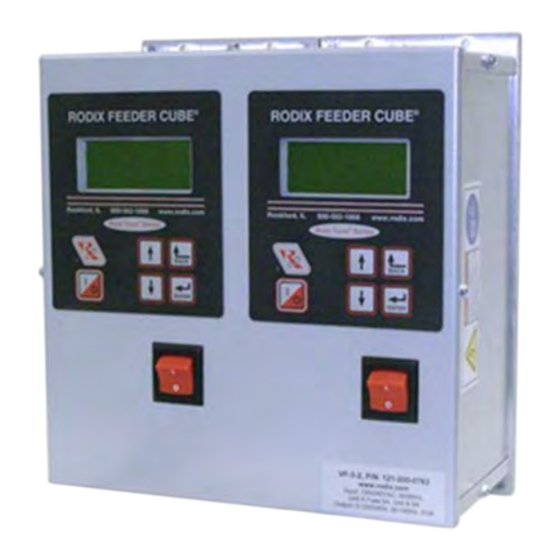
FEEDER CUBE ®
VF-3-2, P/N 121-200-0763
CFR vibration sensor P/N 123-215 is optional
GENERAL PURPOSE MODEL
IMPORTANT: APPLICATION NOTE
Input: 85 - 264 VAC, 50/60 HZ.
Double Unit Fuse Sizes: Unit A 5A, Unit B 5A
Output: 0 - 120/240 VAC
Maximum output voltage matches input voltage
Output Frequency: 5 - 180Hz
Rated Output Current each unit: 3 Amps at 120V or 2 Amps at 240V
Model Information for each unit: The Autotune Series of Variable Frequency Feeder Cubes® generates an output frequency
for feeding that is independent from the power line frequency. An optional vibration sensor, P/N 123-215, can be used to
maintain the vibratory feeder at a constant feed rate. The start/stop operation of the output can be controlled with an optional
parts sensor. For more information on this control, refer to the enclosed Adjustments and Set Up pages. Unit B is interlocked
(subordinate) to the operation of Unit A so that Unit B operates only when Unit A is feeding parts. The interlock can be
reconfigured.
© 2009, 2020 RODIX
RODIX INCORPORATED
TOLL FREE (800) 562-1868, FAX (815) 316-4701
E-mail custserve@rodix.com
rodix.com
.
INC
File No. E183233
11/20/20
Page 1
Advertisement

Related Manuals for Rodix FEEDER CUBE VF-3-2


Summary of Contents for Rodix FEEDER CUBE VF-3-2
- Page 1 For more information on this control, refer to the enclosed Adjustments and Set Up pages. Unit B is interlocked (subordinate) to the operation of Unit A so that Unit B operates only when Unit A is feeding parts. The interlock can be reconfigured. © 2009, 2020 RODIX 11/20/20 Page 1...
- Page 2 RODIX INC. FEEDER CUBE VF Series WIRING DIAGRAM Figure 1 RODIX, INC. Toll Free (800) 562-1868, FAX (815) 316-4701 Email custserve@rodix.com rodix.com VF-3-2 H cover.docx 10/3/2020 Page 2...
- Page 3 Control Menu Layout for VF Series Normal Operation Display Press and hold ‘Enter’ key to enter the program menu or get to the security menu. Then use the “Enter” key to move right from Main Menu to Sub Menu to the Adjustable Setting.
-
Page 4: Adjustments & Set Up
Bowl/Hopper Interlock “sig” and “-“ (see TB2 on the hoppers and linear inline feeders. The VF Series for proper cooling. wiring diagram) can be connected to a Rodix FC-40 output frequency can be adjusted to match the Plus All-Purpose Series control (TB2-11(-) &... -
Page 5: Software Adjustments
E. The “1/0” key allows the user to temporarily stop The variable frequency control is energy efficient menu. The soft start can be set from 0.0 to 10.0 or to start the control’s operation. When the LCD because it recaptures energy from the feeder coils seconds. - Page 6 14. Frequency Settings 15. Resonate Threshold Level The Min Frequency adjustment specifies the The “Frequency” menu contains the portion of the The “Resonate Threshold Level” setting sets the frequency used when the 0-10VDC input is at minimum level of vibration that the control considers menu that controls the frequency settings.
- Page 7 “Inv Al” to activate it. 24. Language Feeder Cube® and Auto Tune® are registered TM of Rodix Inc. E. The auxiliary output can be set so that an air Banner is a registered Trademark of Banner Engineering Corp,...
- Page 8 How to Interlock Two VF Series Controls together 4/8/20 Page 8 1. Remove the run jumper from TB2 terminals 8 & 9 of the subordinate control. 2. Add a wire from term. TB2-1 of the master control to terminal 7 of the subordinate control. 3.
- Page 9 The cable should is in the same direction as the vibration of the E-mail custserve@rodix.com, rodix.com hang straight down from the sensor without touching feeder. The double-ended arrow in figure 1 shows © 2005, 2020 RODIX INC. 123-215 VF-9 CFRsensor .doc...
- Page 10 Rodix controls have been designed with a AUX output. The shield “drain” wire high degree of immunity to electrical should be tied to the chassis in the Rodix RECTIFIER noise; however, depending on the control RELAY DIODE control. The drain wire should be kept...
Need help?
Do you have a question about the FEEDER CUBE VF-3-2 and is the answer not in the manual?
Questions and answers