Table of Contents
Advertisement
Quick Links
Advertisement
Table of Contents

Related Manuals for Kilsen KFP-CX3


Summary of Contents for Kilsen KFP-CX3
- Page 1 KFP-CX3 Operation Manual P/N 501-419103-2-20 • ISS 19JUL21...
- Page 2 Authorized EU manufacturing representative: Carrier Fire & Security B.V., Kelvinstraat 7, 6003 DH Weert, Netherlands. Version REV 02. This document applies to KFP-CX3 control panels with software version 1.0 or later. Certification European Union 2014/30/EU (EMC Directive). Hereby, Carrier declares that this...
-
Page 3: Table Of Contents
The user interface 3 Operator controls and indicators 4 Audible indicators 10 Control panel status indications 11 Control panel operation 18 User levels 18 Public user level operation 18 Operator user level operation 20 Maintenance 28 Regulatory information 29 KFP-CX3 Operation Manual... -
Page 4: Important Information
PRODUCTS, INCLUDING ANY “AUTHORIZED DEALER” OR “AUTHORIZED RESELLER”, IS PROPERLY TRAINED OR EXPERIENCED TO CORRECTLY INSTALL FIRE AND SECURITY RELATED PRODUCTS. For more information on warranty disclaimers and product safety information, please check https://firesecurityproducts.com/policy/product-warning/ or scan the QR code: KFP-CX3 Operation Manual... -
Page 5: Advisory Messages
Note: Note messages advise you of the possible loss of time or effort. They describe how to avoid the loss. Notes are also used to point out important information that you should read. KFP-CX3 Operation Manual... - Page 6 KFP-CX3 Operation Manual...
-
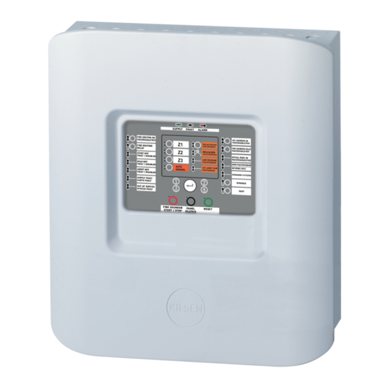
Page 7: Introduction
Introduction This is the operation manual for the KFP-CX3 Extinguishing and Fire Alarm Control Panel. Read these instructions and all related documentation entirely before operating this product. The control panel provides three fire detection zones (Z1, Z2, and Z3) and several manual call point (MCP) inputs that control the extinguishing actions for a single extinguishing area. - Page 8 An alarm in a zone not linked to the extinguishing area or event triggers a fire alarm. In this state, fire sounders and other system features or devices are activated after any configured delay. No extinguishing alarms or devices are activated. KFP-CX3 Operation Manual...
-
Page 9: Control Panel Overview
28. MCP Hold LEDs 13. Expansion I/O Fault/Disabled LED 29. MCP Start LEDs 14. General Disable button and LED 30. Fire Routing Delay button and LED 15. General Test button and LED 31. Fire Routing On button and LEDs KFP-CX3 Operation Manual... -
Page 10: Operator Controls And Indicators
An extinguishing released state if the red Released LED is on steady A flashing yellow LED indicates a fault that prevents the panel from entering the extinguishing activation state. A steady yellow LED indicates that the extinguishing event is disabled. KFP-CX3 Operation Manual... - Page 11 A red LED indicates that the optical warning panel or sign output is activated (to indicate the released state). A flashing yellow LED indicates a wiring fault. A steady yellow LED indicates a disablement or test. KFP-CX3 Operation Manual...
- Page 12 The disablement of some devices requires pressing the button for more than 3 seconds. (See “Disabling other extinguishing devices” on page 26 for further details.) A steady General Disable LED and the corresponding feature or device yellow LED indicates a disablement. KFP-CX3 Operation Manual...
- Page 13 The Reset button may be disabled for up to 30 minutes. Panel Silence button Yellow Silences the control panel buzzer and and LED acknowledges all current events. A steady LED indicates that all current events are acknowledged. KFP-CX3 Operation Manual...
- Page 14 Other system functions remain operational. A steady yellow LED indicates that there is no mains power and the battery power is insufficient. A flashing yellow LED indicates that the mains power is insufficient and there is no battery power. KFP-CX3 Operation Manual...
- Page 15 A flashing LED indicates that a fire routing delay countdown is in progress (fire routing activates when the configured delay elapses). Consult your system installer to determine whether the Fire routing option is configured. KFP-CX3 Operation Manual...
-
Page 16: Audible Indicators
An intermittent tone can indicate that: • The control panel is in a fault condition. • The control panel is in the last 10 seconds of a delay countdown before activating the extinguishing actuator (extinguishing release is imminent). KFP-CX3 Operation Manual... -
Page 17: Control Panel Status Indications
Fire Routing LED flashes. Consult your system installer or maintenance contractor to determine whether your system has a zone configured for fire-only operation. The control panel buzzer sounds continuously. KFP-CX3 Operation Manual... - Page 18 The extinguishing event is enabled automatically when the fault is fixed and the control panel is reset. A prevented extinguishing event is indicated by a flashing yellow Preactivation LED and by the fault/disabled LED of the device that prevented the event. KFP-CX3 Operation Manual...
- Page 19 If the hold manual call point is pressed while in extinguishing activation: • The extinguishing process is paused. • MCP Hold LED: Steady (depends on the hold mode configured). Consult your system installer to determine which hold mode was configured for your system. KFP-CX3 Operation Manual...
- Page 20 Optical Panel On LED: Steady to indicate that the output to activate the optical warning panel or sign is active. • Reset LED: Flashing slowly, to indicate that manual reset is disabled until the configured delay expires. KFP-CX3 Operation Manual...
- Page 21 General Disable LED and a steady yellow Optical Panel On LED. Disabled start, hold, or abort extinguishing manual call points are indicated by a steady General Disable LED and a steady yellow LED for MCP Start, MCP Hold, or MCP Abort. There is no audible indication. KFP-CX3 Operation Manual...
- Page 22 There is no audible indicator. WARNING: Risk of death or serious injury. Disconnect the extinguishing agent actuator from the control panel before you issue the actuator output test command. When you confirm the test command, the actuator output is activated immediately. KFP-CX3 Operation Manual...
- Page 23 (The Out of Service state is latched.) Note: When the control panel indicates out of service, the fire alarm detection in your system is inactive and your site is not protected. Contact your installation or maintenance contractor immediately to solve the problem. KFP-CX3 Operation Manual...
-
Page 24: Control Panel Operation
Public user level operation lets you: • Acknowledge a system event and silence the control panel buzzer • Cancel an active fire sounders delay • Cancel an active fire routing delay • Perform a control panel LED and buzzer test KFP-CX3 Operation Manual... - Page 25 The control panel buzzer sounds continuously. The test continues for as long as the Test button remains pressed (with an automatic timeout of 12 seconds). When the test is completed the control panel returns to its former state. KFP-CX3 Operation Manual...
-
Page 26: Operator User Level Operation
Reset button may remain disabled for up to 30 minutes. Consult your system installer for the time configured. When the Reset LED is steady the control panel can be reset. KFP-CX3 Operation Manual... - Page 27 Note that sounder functionality is subject to system configuration and, depending on what your installation or maintenance contractor has selected, silenced sounders may restart automatically if another alarm event is detected. Contact your installation or maintenance contractor to determine the configuration details for your site. KFP-CX3 Operation Manual...
- Page 28 To enable the fire sounders, press the General Disable button, and then press the Fire Sounders Delay button again. To enable the extinguishing sounders, press the General Disable button, and then press the Extinguishing Sounders On button again. KFP-CX3 Operation Manual...
- Page 29 Disabled fire routing does not operate or indicate a fault if there is a fire alarm. Disabling or enabling a fire routing delay To disable a configured (and enabled) fire routing delay, press the Fire Routing Delay button. To enable the delay, press the button again. KFP-CX3 Operation Manual...
- Page 30 A steady General Disable LED • A steady yellow Zone LED To enable the zone, press the General Disable button, and then press the Zone button again. Note: No fire alarm or faults are indicated for disabled zones. KFP-CX3 Operation Manual...
- Page 31 (configurable up to 60 seconds) before the control panel enters extinguishing released state. Note: Some faults or disablements of extinguishing devices can prevent or disable the extinguishing event. See “Extinguishing event prevented” on page 12 for more details. KFP-CX3 Operation Manual...
- Page 32 A steady test LED for the corresponding device To exit from a test condition, press the General Test button for more than 3 seconds, press the 1 and 3 buttons to select the option, and then press Enter. KFP-CX3 Operation Manual...
- Page 33 Pressing the Manual Mode button again switches the control panel back to automatic-manual mode. The Manual Mode LED turns off. In automatic-manual mode, the detection zones in the extinguishing area and the MCP Start point can generate the extinguishing event. KFP-CX3 Operation Manual...
-
Page 34: Maintenance
Keep the outside and inside of the control panel clean. Carry out periodic cleaning using a damp cloth for the outside. Do not use products containing solvents to clean the unit. Do not clean the inside of the cabinet with liquid products. KFP-CX3 Operation Manual... -
Page 35: Regulatory Information
European standards for electrical safety and electromagnetic compatibility These control panels have been designed in accordance with the following European standards for electrical safety and electromagnetic compatibility: • EN 62368-1 • EN 50130-4 • EN 61000-6-3 • EN 61000-3-2 • EN 61000-3-3 KFP-CX3 Operation Manual... - Page 36 Carrier Fire & Security B.V., Kelvinstraat 7, 6003 DH Weert, Netherlands. Year of first CE marking Declaration of Performance 360-3106-0199 number Product identification See model number on product identification label Intended use See the product Declaration of Performance Declared performance See the product Declaration of Performance KFP-CX3 Operation Manual...
Need help?
Do you have a question about the KFP-CX3 and is the answer not in the manual?
Questions and answers