
Related Manuals for Kilsen KFP-AF Series


Summary of Contents for Kilsen KFP-AF Series
-
Page 1: Control Panel Installation
KFP-AF Series Fire Alarm Control Panel Installation Manual P/N 501-405103-1-20 • REV 2.0 • ISS 03MAR11... - Page 2 Copyright © 2011 UTC Fire & Security. All rights reserved. Trademarks and The KFP-AF Series name and logo are trademarks of patents UTC Fire & Security. Other trade names used in this document may be trademarks or registered trademarks of the manufacturers or vendors of the respective products.
-
Page 3: Table Of Contents
Maintenance 87 Fire alarm system maintenance 88 Battery maintenance 89 Chapter 5 Technical specifications 91 Appendix A Default configurations 99 Appendix B Menu maps 101 Appendix C Regulatory information 109 Index 111 KFP-AF Series Fire Alarm Control Panel Installation Manual... -
Page 4: Important Information
Important information Introduction This is the installation manual for the KFP-AF Series Fire Alarm Control Panels. Read these instructions and all related documentation entirely before installing or operating this product. Firmware compatibility Information in this document covers control panels with firmware version 2.0 or later. - Page 5 Note messages advise you of the possible loss of time or effort. They describe how to avoid the loss. Notes are also used to point out important information that you should read. KFP-AF Series Fire Alarm Control Panel Installation Manual...
- Page 6 KFP-AF Series Fire Alarm Control Panel Installation Manual...
-
Page 7: Introduction
The user interface 4 Front panel controls and indicators 5 LCD controls and indicators 8 Indication of remote and local events on the LCD 10 Acoustic indicators 10 Summary of conditions 10 KFP-AF Series Fire Alarm Control Panel Installation Manual... -
Page 8: Product Range
For more information, see “Firenet configuration” on page 50. Fire routing and fire protection control and indication In this document, information on control and indication for fire routing and fire protection applies only to control panels that include those features. KFP-AF Series Fire Alarm Control Panel Installation Manual... -
Page 9: Product Compatibility
Products compatible with these control panels are listed in the supplied compatibility list. Only those products specified in the compatibility list are guaranteed to be compatible with these control panels. For further details contact your local supplier. KFP-AF Series Fire Alarm Control Panel Installation Manual... -
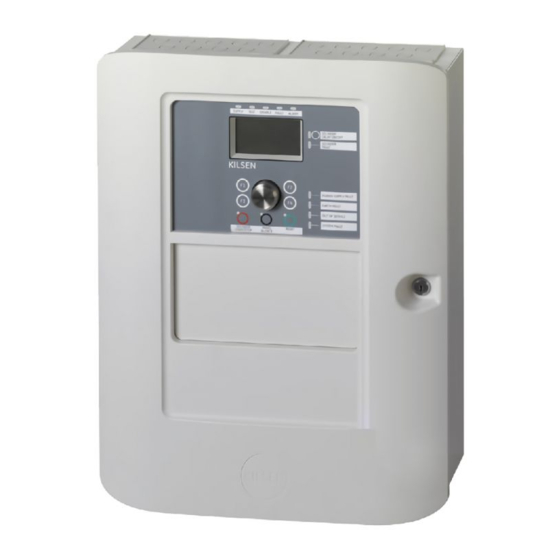
Page 10: Control Panel Overview
22. Fire Routing On/Acknowledged button and 11. Low Battery LED 12. System Fault LED For a detailed overview of front panel controls and indicators, see “Front panel controls and indicators” on page 5. KFP-AF Series Fire Alarm Control Panel Installation Manual... -
Page 11: Front Panel Controls And Indicators
LED A flashing LED indicates that fire protection has been activated. A steady LED indicates that the fire protection signal has been acknowledged by the remote monitoring equipment. KFP-AF Series Fire Alarm Control Panel Installation Manual... - Page 12 Flashing indicates that a delay is counting (sounders are activated when the configured delay elapses or when the delay is cancelled) • Off indicates that the sounders are off (or will be deactivated shortly) KFP-AF Series Fire Alarm Control Panel Installation Manual...
- Page 13 The fire routing indication displays the acknowledged status but not the activation status (the acknowledgement status takes priority). For more information on output groups, see “Output groups” on page 72. KFP-AF Series Fire Alarm Control Panel Installation Manual...
-
Page 14: Lcd Controls And Indicators
6. Soft keys (menu options linked to function buttons F1, F2, F3, and F4) 7. Jog dial 8. Function buttons F1, F2, F3, and F4 9. Local control panel ID (in a fire network) KFP-AF Series Fire Alarm Control Panel Installation Manual... - Page 15 This icon indicates that the system has detected a Manual call point alarm [1] manual call point alarm. [1] These icons appear in the message display area with the notification details. KFP-AF Series Fire Alarm Control Panel Installation Manual...
-
Page 16: Indication Of Remote And Local Events On The Lcd
Input activation An input is activated (subject to configuration) Output group activation An output group is activated New node in the fire network A control panel has been added to the fire network KFP-AF Series Fire Alarm Control Panel Installation Manual... - Page 17 [1] A rule consists of one or more states (combined by Boolean operators) that are configured to trigger specific system actions after a specific confirmation time. Rules are created using the configuration utility. KFP-AF Series Fire Alarm Control Panel Installation Manual...
- Page 18 Chapter 1: Introduction KFP-AF Series Fire Alarm Control Panel Installation Manual...
-
Page 19: Installation
Connecting inputs 22 Connecting outputs 23 Connecting the mains power supply 25 Connecting the batteries 26 Connecting expansion boards 26 Connecting a fire network 26 Connecting an external printer or ASCII terminal 28 KFP-AF Series Fire Alarm Control Panel Installation Manual... -
Page 20: Cabinet And Pcb Layout
5. USB type B connector 13. Battery area 6. USB type A connectors 14. Mounting holes 7. COM0 and COM1 serial ports 15. User interface connector 8. COM0 and COM1 interface connectors KFP-AF Series Fire Alarm Control Panel Installation Manual... - Page 21 6. USB type A connectors 13. Battery area 7. COM0 and COM1 serial ports 14. User interface connector Figure 5: Small cabinet with main PCB and chassis removed to show power supply KFP-AF Series Fire Alarm Control Panel Installation Manual...
-
Page 22: Cabinet Installation
To fix the cabinet to the wall: 1. Hold the cabinet to the wall at the required installation height. 2. Ensure that the cabinet is level using the built-in spirit level and mark drill points on the wall. KFP-AF Series Fire Alarm Control Panel Installation Manual... -
Page 23: Adding The Menu Inserts
Add the control panel interface menus as shown below. The inserts are numbered from 1 to 4, and are inserted at the location indicated (with the printed area facing the front of the control panel). Figure 7: Adding the menu inserts KFP-AF Series Fire Alarm Control Panel Installation Manual... -
Page 24: Connections
(EMI) conditions and installation testing. Securing cables Use 20 mm cable glands to ensure clean and secure connections. All cables should be fed through the cable guides in the cabinet housing to eliminate movement. KFP-AF Series Fire Alarm Control Panel Installation Manual... -
Page 25: Overview Of Fire System Connections
Chapter 2: Installation Overview of fire system connections Figure 8: Overview of typical fire system connections with a single Class A loop For input activation characteristics, see “Connecting inputs” on page 22. KFP-AF Series Fire Alarm Control Panel Installation Manual... -
Page 26: Connecting Loops
Keep loop cabling away from high-voltage cables (or any other source of interference). • Star, stub, and T-tap configurations are not recommended. • Install loop devices with a high current consumption as close as possible to the control panel. KFP-AF Series Fire Alarm Control Panel Installation Manual... - Page 27 Connect Class B loops as shown in Figure 10 below. Connection may be made to either the A connectors (as shown) or to the B connectors, but not to both. Class B loops are supervised for short circuit. Figure 10: Class B loop connection KFP-AF Series Fire Alarm Control Panel Installation Manual...
-
Page 28: Connecting Loop Devices
60.2 Ω active value 8 kΩ Active 10 kΩ value 20.2 kΩ Normal 60.2 Ω Short circuit High impedance fault 8 kΩ < value < 10 kΩ 20.2 kΩ Open circuit KFP-AF Series Fire Alarm Control Panel Installation Manual... -
Page 29: Connecting Outputs
If an output is not used, the 15 kΩ end-of-line resistor must be installed across the unused terminals to avoid an open circuit fault on the output. Unused outputs must be configured as Class B. KFP-AF Series Fire Alarm Control Panel Installation Manual... - Page 30 Connecting fire and fault outputs Connect the FIRE OUT SUPERVIS and FAULT OUT SUPERVIS outputs as shown in Figure 8 on page 19. A 15 kΩ end-of-line resistor is required. KFP-AF Series Fire Alarm Control Panel Installation Manual...
-
Page 31: Connecting The Mains Power Supply
The default power setting is 230 VAC. For 115 VAC operation use a small screwdriver to change the power setting switch, located on the side of the power supply unit, as shown in Figure 12 on page 26. KFP-AF Series Fire Alarm Control Panel Installation Manual... -
Page 32: Connecting The Batteries
Each network board has two ports. Each port is connected (point to point) to the corresponding ports of the network board in another control panel. Figure 13: Network board connections KFP-AF Series Fire Alarm Control Panel Installation Manual... - Page 33 For bus configuration (Class B), connect control panels as shown below. Figure 15: Fire network bus configuration KFP-AF Series Fire Alarm Control Panel Installation Manual...
-
Page 34: Connecting An External Printer Or Ascii Terminal
Table 13: Serial port connections Serial port Output device COM0 EPSON LX300 printer COM1 ASCII terminal See Figure 3 on page 14 for COM serial port and RS-232 interface board connector locations. KFP-AF Series Fire Alarm Control Panel Installation Manual... -
Page 35: Configuration And Commissioning
ID configuration 49 Regional options 49 Firenet configuration 50 Communications configuration 54 Other settings 55 Configuration 57 Expansion board configuration 58 Load auxiliary files 59 Firmware updates 60 Field configuration 60 Autosetup 61 KFP-AF Series Fire Alarm Control Panel Installation Manual... -
Page 36: Introduction
The control panel automatically exits from a restricted user level and reverts to the public user level after a few minutes if no button is pressed. The automatic timeout period depends on the active user level, as shown below. KFP-AF Series Fire Alarm Control Panel Installation Manual... -
Page 37: Configuration Overview
An action is the activation of output groups or the execution of programmable commands in the system. Rules programming is also known as cause and effect programming, I/O logic activation etc. KFP-AF Series Fire Alarm Control Panel Installation Manual... - Page 38 Press the jog dial to confirm the selection. The control panel ID on the LCD is white text with a dark background when the jog dial is active (the control panel is waiting for input). KFP-AF Series Fire Alarm Control Panel Installation Manual...
- Page 39 Select this option to exit the configuration process without storing or applying the current configuration change. Note: When updating multiple configuration settings, we recommend that you save after each change, and then apply all changes from the Main menu. KFP-AF Series Fire Alarm Control Panel Installation Manual...
-
Page 40: Maintenance Level Operation And Configuration
Date and time Select the Date and time option to change the control panel date and time. To change the date and time: 1. Select Panel setup from the Main menu. KFP-AF Series Fire Alarm Control Panel Installation Manual... - Page 41 4. Enter the time that day mode starts using the hh:mm format (for example, 08:00). 5. Enter the time that night mode starts using the hh:mm format (for example, 21:00). 6. Press F4 (Enter), and then press F1 (Back). KFP-AF Series Fire Alarm Control Panel Installation Manual...
- Page 42 6. Enter any additional holiday periods as described in steps 3 and 4. 7. Press F4 (Enter), and then press F1 (Back). 8. Press F1 (Save), F3 (Apply), F4 (Discard), or F2 (Exit). Remember to apply saved settings from the Main menu. KFP-AF Series Fire Alarm Control Panel Installation Manual...
- Page 43 By default, all delays are disabled when the control panel is in night mode. 6. Press F4 (Enter), and then press F1 (Back). 7. Press F1 (Save), F3 (Apply), F4 (Discard), or F2 (Exit). Remember to apply saved settings from the Main menu. KFP-AF Series Fire Alarm Control Panel Installation Manual...
-
Page 44: The Communications Menu
6. Press F1 (Save), F3 (Apply), F4 (Discard), or F2 (Exit). Remember to apply saved settings from the Main menu. Note: This feature requires TCP/IP and e-mail server details to be configured. KFP-AF Series Fire Alarm Control Panel Installation Manual... -
Page 45: The Disable/Enable Menu
For remote disablements, enter the Firenet ID of the feature or device to be disabled, and then press the jog dial to confirm the disablement. KFP-AF Series Fire Alarm Control Panel Installation Manual... -
Page 46: The Test Menu
3. Select the zone to test, and then press the jog dial to start the test. Press the jog dial again to end the test for the selected zone. You can select and test up to a maximum of four zones to test at the same time. KFP-AF Series Fire Alarm Control Panel Installation Manual... - Page 47 3. Select the output you want to test, and then select YES (to activate the output) or NO (to deactivate the output). 4. Press the jog dial again to end the test. 5. Press F2 (Exit) to exit the menu. KFP-AF Series Fire Alarm Control Panel Installation Manual...
- Page 48 4. Select Active then select YES (to start the test) or NO (to stop the test). 5. Press the jog dial again to end the test. 6. Press F2 (Exit) to exit the menu. KFP-AF Series Fire Alarm Control Panel Installation Manual...
-
Page 49: The Reports Menu
Select this option to view all devices reporting a fault condition. Revision Select this option to view your control panel software revision, control panel configuration revision, and system boards serial number data. KFP-AF Series Fire Alarm Control Panel Installation Manual... - Page 50 3. Press F2 (Exit) to exit the menu. The event log can include a maximum of 9,999 entries. When the maximum number of entries is reached, the oldest entries are deleted as new entries are recorded. KFP-AF Series Fire Alarm Control Panel Installation Manual...
- Page 51 2. Insert a USB flash drive into either of the USB connectors. 3. Close the control panel cabinet door. 4. Select Reports from the Main menu. 5. Select Save report, and then select ALL or the report to be saved. KFP-AF Series Fire Alarm Control Panel Installation Manual...
-
Page 52: The Password Setup Menu
4. Press F4 (Enter), and then press F1 (Back). 5. Press F1 (Save), F3 (Apply), F4 (Discard), or F2 (Exit). Remember to apply saved settings from the Main menu. KFP-AF Series Fire Alarm Control Panel Installation Manual... - Page 53 Usernames help to identify user session activity in the event log. 4. Press F4 (Enter), and then press F1 (Back). 5. Press F1 (Save), F3 (Apply), F4 (Discard), or F2 (Exit). Remember to apply saved settings from the Main menu. KFP-AF Series Fire Alarm Control Panel Installation Manual...
-
Page 54: Installer Level Operation And Configuration
Select this option to load a new configuration, to save the current configuration file to a USB flash drive, to restore the previous configuration, or to restore the default factory settings. Expansion boards Select this option to configure any installed expansion boards. KFP-AF Series Fire Alarm Control Panel Installation Manual... -
Page 55: Id Configuration
3. Select the operating mode. 4. Press F4 (Enter), and then press F1 (Back). 5. Press F1 (Save), F3 (Apply), F4 (Discard), or F2 (Exit) Remember to apply saved settings from the Main menu. KFP-AF Series Fire Alarm Control Panel Installation Manual... -
Page 56: Firenet Configuration
NO (to remove the control panel from the network). 5. Press F4 (Enter), and then press F1 (Back). 6. Press F1 (Save), F3 (Apply), F4 (Discard), or F2 (Exit). Remember to apply saved settings from the Main menu. KFP-AF Series Fire Alarm Control Panel Installation Manual... - Page 57 The default setting is YES (all control panels in the fire network are repeated). To change the repeater map settings: 1. Select Panel setup from the Main menu. 2. Select Firenet, and then select Repeater map. KFP-AF Series Fire Alarm Control Panel Installation Manual...
- Page 58 3. Select the types of events to repeat. 4. Press F4 (Enter), and then press F1 (Back). 5. Press F1 (Save), F3 (Apply), F4 (Discard), or F2 (Exit). Remember to apply saved settings from the Main menu. KFP-AF Series Fire Alarm Control Panel Installation Manual...
- Page 59 To change the network class settings: 1. Select Panel setup from the Main menu. 2. Select Firenet, and then select Class B. 3. Select YES (for Class B network) or NO (for Class A network). KFP-AF Series Fire Alarm Control Panel Installation Manual...
-
Page 60: Communications Configuration
For correct operation, TCP/IP and e-mail server details must be configured (see “E- mail server” on page 55). Note: Maintenance users are also able to modify settings for this service. KFP-AF Series Fire Alarm Control Panel Installation Manual... -
Page 61: Other Settings
1. Select Panel setup from the Main menu. 2. Select Other settings, and then select 24V AUX config. 3. Select YES or NO for deactivation during reset. 4. Select YES or NO for deactivation when running on battery power. KFP-AF Series Fire Alarm Control Panel Installation Manual... - Page 62 3. Select YES or NO. 4. Press F4 (Enter), and then press F1 (Back). 5. Press F1 (Save), F3 (Apply), F4 (Discard), or F2 (Exit). Remember to apply saved settings from the Main menu. KFP-AF Series Fire Alarm Control Panel Installation Manual...
-
Page 63: Configuration
USB type B connectors (see Figure 3 on page 14). Close the control panel door. 2. Select Panel setup from the Main menu. 3. Select Configuration, and then select Load configuration. 4. Select the configuration file to load. KFP-AF Series Fire Alarm Control Panel Installation Manual... -
Page 64: Expansion Board Configuration
By default repeater panels have the network board configured as installed. To add an expansion board: 1. Select Panel setup from the Main menu. 2. Select Expansion boards. KFP-AF Series Fire Alarm Control Panel Installation Manual... -
Page 65: Load Auxiliary Files
1. Open the control panel door and insert the USB flash drive with the required files into either of the USB type B connectors (see Figure 3 on page 14). Close the control panel door. 2. Select Panel setup from the Main menu. KFP-AF Series Fire Alarm Control Panel Installation Manual... -
Page 66: Firmware Updates
Select this option to configure output group delays and regional investigation time options. Delays can be global, per output group, or per zone. Loop class Select this option to configure the installation loop wiring Class (Class A or Class B). KFP-AF Series Fire Alarm Control Panel Installation Manual... -
Page 67: Autosetup
Select the Loop device configuration option to manually add devices or to change the default configuration settings after autosetup. To add a device or to change a device configuration: 1. Select Field setup from the Main menu, and then select Loop device configuration. KFP-AF Series Fire Alarm Control Panel Installation Manual... -
Page 68: Address Device
Area configuration Select this option to define areas. An area is a group of zones used for alarm confirmation. [1] This option is only available if an optional zone indicator board is installed. KFP-AF Series Fire Alarm Control Panel Installation Manual... - Page 69 LED (top left) of the board. The remaining zones for the corresponding control panel follow sequentially, as shown in Table 29 on page 64. Note: This option is only available if an optional zone indicator board is installed. KFP-AF Series Fire Alarm Control Panel Installation Manual...
- Page 70 Select the Zone configuration option to configure the zone type (normal or confirmed), to enter a zone description, and to enable or disable a zone. Zone configuration options are shown in the table below. KFP-AF Series Fire Alarm Control Panel Installation Manual...
- Page 71 Zone confirmation is an alarm coincidence configuration method designed to reduce nuisance alarms. A first alarm event places the zone and the control panel into alert status. Full alarm status is not confirmed until a second alarm is KFP-AF Series Fire Alarm Control Panel Installation Manual...
- Page 72 The alarm is confirmed by two different manual call points in the same local area irrespective of which device first reports the alarm event. A detector alarm places the zone in alert status. KFP-AF Series Fire Alarm Control Panel Installation Manual...
- Page 73 When configuring a confirmed zone, remember that remote zones with the same zone number can activate a control panel alarm without confirmation. To avoid this type of unwanted alarm, configure the remote zones accordingly. KFP-AF Series Fire Alarm Control Panel Installation Manual...
-
Page 74: Panel I/O Configuration
Logged activation. An unlatched condition that generates no indications but it is only stored on the event log. Detector alarm. Note: this input type can be used for connecting to aspirating detector Fire1 outputs. KFP-AF Series Fire Alarm Control Panel Installation Manual... - Page 75 FBFSD FBF sounders disable. The input is configured to interface to remote FBF equipment to disable or enable sounders. UKSB British school class change. Activation activates sounders for school class change indication. KFP-AF Series Fire Alarm Control Panel Installation Manual...
- Page 76 6. Select the output Class (Class A or Class B). The default setting is Class B. 7. Press F4 (Enter), and then press F1 (Back). 8. Press F1 (Save), F3 (Apply), F4 (Discard), or F2 (Exit). KFP-AF Series Fire Alarm Control Panel Installation Manual...
- Page 77 This includes enable/disable configuration options. For example, if the OUT1 type is changed to PRG and Group-n changed to 5, then the configuration of the paired OUT2 is updated automatically to match these settings. KFP-AF Series Fire Alarm Control Panel Installation Manual...
-
Page 78: Output Groups
A short text description for the output group The default control panel output group configuration is shown in Table 37 on page 73. Outputs are assigned to the default output groups during autosetup (see “Autosetup” on page 61). KFP-AF Series Fire Alarm Control Panel Installation Manual... - Page 79 Output groups can be activated by any of the following: • Zones activation with delays • Output group confirmation for specific outputs (EN 54-2 type C) • Logic rules (configured via the configuration utility PC application) KFP-AF Series Fire Alarm Control Panel Installation Manual...
- Page 80 If alarm confirmation is required then the output group is activated only when both configured alarm confirmation states are detected during the confirmation delay period. 6. Enter the confirmation delay in seconds (0 to 999). KFP-AF Series Fire Alarm Control Panel Installation Manual...
-
Page 81: Delays Configuration
These output groups can be configured individually or all output group types at the same time. All zones are programmed with the same setting: global delay or no activation. Configurable options for output group delays are shown in the table below. KFP-AF Series Fire Alarm Control Panel Installation Manual... - Page 82 (day/night mode), remote equipment by means of a programmed input, or the user interface delay buttons. By default, the control panel does not process delays when operating in night mode. Remember that night mode can be activated by the day/night mode KFP-AF Series Fire Alarm Control Panel Installation Manual...
- Page 83 5. Enter the required delay in seconds. The maximum delay value for sounder, fire routing, and fire protection output groups is 600 seconds. The maximum delay value for program output groups is 999 seconds. KFP-AF Series Fire Alarm Control Panel Installation Manual...
- Page 84 Warning time. Select this option to configure the warning time when the control panel is configured to use a warning tone for a second stage sounders application. For standard applications with no warning tone requirement, this time must be 0. KFP-AF Series Fire Alarm Control Panel Installation Manual...
- Page 85 See “Sounders silence disable time” on page 82 for more information on this option. 7. Press F4 (Enter), and then press F1 (Back). 8. Press F1 (Save), F3 (Apply), F4 (Discard), or F2 (Exit). Remember to apply saved settings from the Main menu. KFP-AF Series Fire Alarm Control Panel Installation Manual...
- Page 86 If the alarm is not acknowledged during the configured fire routing delay (by pressing the Sounders Start/Stop button), then the extended fire routing delay is not activated. [1] Sounder delay must be configured as 0 seconds for this option. KFP-AF Series Fire Alarm Control Panel Installation Manual...
- Page 87 The optional delay before the sounders activate the warning tone Delay [1] The optional delay before the sounders activate the evacuation tone [1] To configure these values, see “Sounder, fire routing, fire protection, and program output group delays” on page 75. KFP-AF Series Fire Alarm Control Panel Installation Manual...
- Page 88 In the time between the end of the configured disable time and the end of the configured sounder delay (when the Sounder Start/Stop LED is flashing), pressing the Sounder Start/Stop button silences sounders (before activation). KFP-AF Series Fire Alarm Control Panel Installation Manual...
-
Page 89: Loop Class Configuration
2. Select the diagnostics test you require. If the individual device test is selected, enter the loop and address details for the device to be inspected (for example, 1.089 for device 89 on loop 1). KFP-AF Series Fire Alarm Control Panel Installation Manual... -
Page 90: Password Setup
Remember to apply saved settings from the Main menu. To delete a user account: 1. Select Password setup from the Main menu, and then select Manage users. A list of all user accounts is displayed. KFP-AF Series Fire Alarm Control Panel Installation Manual... - Page 91 2. Select the required security setting. 3. Press F4 (Enter), and then press F1 (Back). 4. Press F1 (Save), F3 (Apply), F4 (Discard), or F2 (Exit). Remember to apply saved settings from the Main menu. KFP-AF Series Fire Alarm Control Panel Installation Manual...
-
Page 92: Commissioning
That under the alarm conditions (with all applicable devices activated), the current consumption does not exceed the power supply specifications (if the batteries are not activated the current consumption is within the specifications) KFP-AF Series Fire Alarm Control Panel Installation Manual... -
Page 93: Maintenance
Chapter 4 Maintenance Summary This chapter includes information on fire alarm system and battery maintenance. Content Fire alarm system maintenance 88 Battery maintenance 89 KFP-AF Series Fire Alarm Control Panel Installation Manual... -
Page 94: Fire Alarm System Maintenance
Keep the outside and inside of the control panel clean. Carry out periodic cleaning using a damp cloth for the outside. Do not use products containing solvents to clean the unit. Do not clean the inside of the cabinet with liquid products. KFP-AF Series Fire Alarm Control Panel Installation Manual... -
Page 95: Battery Maintenance
In addition to the above, the following battery charger faults may display: • Battery charger: sensor HI • Battery charger: sensor LO • Battery charger: overvoltage • Battery charger: undervoltage • Battery charger: compensation KFP-AF Series Fire Alarm Control Panel Installation Manual... - Page 96 To power up the control panel from the batteries, press the battery start button on the control panel PCB (marked as BAT, see Figure 21 below). Keep the button pressed for approximately five seconds. Figure 21: Battery start-up button KFP-AF Series Fire Alarm Control Panel Installation Manual...
-
Page 97: Technical Specifications
Loop specifications 92 Power supply specifications 92 Battery and battery charger specifications 93 LCD specifications 93 Communication port specifications 93 Fire network specifications 93 Input/Output specifications 94 Mechanical and environmental specifications 95 KFP-AF Series Fire Alarm Control Panel Installation Manual... -
Page 98: Loop Specifications
12 mA at 24 VDC 40-zone board 14 mA at 24 VDC Quiescent current (Imax a) 2.5 A max. at 24 VDC Alarm current (Imax b) 4 A max. at 24 VDC KFP-AF Series Fire Alarm Control Panel Installation Manual... -
Page 99: Battery And Battery Charger Specifications
USB device port USB 2.0, type B connector Fire network specifications Maximum distance between 1.2 km two control panels Maximum capacity 32 loops and 32 nodes Communication protocol Proprietary protocol based on RS-485 KFP-AF Series Fire Alarm Control Panel Installation Manual... -
Page 100: Input/Output Specifications
1 supervised output: reverse polarity, end-of-line resistor 15 kΩ, 1/4 W 1 potential free relay: C/NO/NC Maximum output current Supervised output 350 mA per output for all temperature ranges Relay output 2 A / 30 VDC KFP-AF Series Fire Alarm Control Panel Installation Manual... -
Page 101: Mechanical And Environmental Specifications
18 x Ø 20 mm at top of cabinet 2 x Ø 20 mm at bottom of cabinet IP rating IP30 Environmental Operating temperature −5 to +40ºC Storage temperature −20 to +50ºC Relative humidity 10 to 95% noncondensing KFP-AF Series Fire Alarm Control Panel Installation Manual... - Page 102 Chapter 5: Technical specifications Figure 22: Large cabinet dimensions and views KFP-AF Series Fire Alarm Control Panel Installation Manual...
- Page 103 Chapter 5: Technical specifications Figure 23: Small cabinet dimensions and views KFP-AF Series Fire Alarm Control Panel Installation Manual...
- Page 104 Chapter 5: Technical specifications KFP-AF Series Fire Alarm Control Panel Installation Manual...
-
Page 105: Appendix A Default Configurations
All sounders to output group 1 (sounders) All relay/non-supervised outputs to output group 301 (program) All extinguishing modules to output group 801 (extinguishing) All inputs configured as technical alarm latched KFP-AF Series Fire Alarm Control Panel Installation Manual... - Page 106 Technical alarm latched (T_AL) Delays All delays to 0 in all zones Sounder, fire routing, fire protection, and program groups to be activated by all zones Sounders silence disable time 60 seconds Expansion boards None KFP-AF Series Fire Alarm Control Panel Installation Manual...
-
Page 107: Appendix B Menu Maps
Output groups Remote disable Test Zone test Output test Panel outputs Loop outputs Output group test Locate device Service mode Remote test UI test Indicators test Keyboard test LCD test Battery test KFP-AF Series Fire Alarm Control Panel Installation Manual... - Page 108 Change password Manage users Installer user level Menu level 1 Menu level 2 Menu level 3 Field setup Autosetup Loop device configuration Address device Zone configuration Initial zone ZI initial zone Zone configuration KFP-AF Series Fire Alarm Control Panel Installation Manual...
- Page 109 Command filter Class B Communications TCP/IP Email accounts Email server Remove USB device Other settings 24V aux. configuration Fault mask Buzzer Re-sound sounders Device LEDs School bells Configuration Restore configuration Load configuration KFP-AF Series Fire Alarm Control Panel Installation Manual...
- Page 110 Loop values UI test Indicator test Keyboard test LCD test Battery test Reports Event log View all Clear Attention required Revision Firmware revision Configuration revision Serial numbers Contact details Zone status Zone mapping KFP-AF Series Fire Alarm Control Panel Installation Manual...
- Page 111 Date and time Communications Email accounts Remove USB device Disable/enable Zones Panel outputs Panel inputs Output groups Remote disable Test Output test Panel outputs Service mode Remote test UI test Indicators test KFP-AF Series Fire Alarm Control Panel Installation Manual...
- Page 112 ZI Initial zone Panel I/O configuration Panel inputs Panel setup ID configuration Date and time Regional options Firenet Firenet map Firenet opmode Repeater map Global controls Event filter Command filter Class B KFP-AF Series Fire Alarm Control Panel Installation Manual...
- Page 113 Locate device Service mode Remote test UI test Indicators test Keyboard test LCD test Battery test Reports Event log View all Clear Attention required Revision Firmware revision Configuration revision Serial numbers Contact details KFP-AF Series Fire Alarm Control Panel Installation Manual...
- Page 114 Menu level 2 Menu level 3 Panel I/O status Firenet status Save reports Current events Event log Attention required Panel I/O status Firenet status Alarm counter Password setup Change password Manage users Secure access KFP-AF Series Fire Alarm Control Panel Installation Manual...
-
Page 115: Appendix C Regulatory Information
[1] Excluding repeaters and control panels operating in EN 54-2 Evacuation or NBN modes [2] Excluding repeaters, control panels without fire routing, and control panels with fire routing operating in NBN mode [3] Excluding repeaters and control panels without fire protection controls [4] Excluding repeaters KFP-AF Series Fire Alarm Control Panel Installation Manual... - Page 116 These control panels have been designed in accordance with the following European standards for electrical safety and electromagnetic compatibility: • EN 60950-1 • EN 50130-4 • EN 61000-6-3 • EN 61000-3-2 • EN 61000-3-3 KFP-AF Series Fire Alarm Control Panel Installation Manual...
-
Page 117: Index
55 fire network, 26 enable device, 39 inputs, 22 enable input, 70 mains power, 25 enable output, 71 mains terminal block, 25 enable zone, 64 outputs, 23 event filter, 52 KFP-AF Series Fire Alarm Control Panel Installation Manual... - Page 118 94 loop class configuration, 83 LCD, 93 loop, 92 mechanical and environmental, 95 power supply, 92 mains power requirements, 25 supply fault indication, 26 mains power selection (115/230 VAC), 25 KFP-AF Series Fire Alarm Control Panel Installation Manual...
- Page 119 47, 85 delete, 47, 84 edit, 46, 84 user levels, 30 ZI initial zone, 63 zone alarm confirmation, 65 zone configuration, 62, 64 zone confirmation, 64 zone test, 40 KFP-AF Series Fire Alarm Control Panel Installation Manual...
Need help?
Do you have a question about the KFP-AF Series and is the answer not in the manual?
Questions and answers