Table of Contents
Advertisement
Quick Links
www.ti.com
EVM User's Guide: TPS62A01PEVM-018, TPS62A01APEVM- 018,
TPS62A02PEVM-018, TPS62A02APEVM-018
TPS62A0xPEVM-018 and TPS62A0xAPEVM-018
Evaluation Modules
Description
The TPS62A0xPEVM-018 and
TPS62A0xAPEVM-018 facilitate the evaluation of the
TPS62A0xP and TPS62A0xAP family of 1 A and
2 A, step-down converters in 2.9-mm × 2.8- mm
SOT23-6 packages. The EVM converts a 2.5V to 5.5V
input voltages maintaining the desired output voltage
regulation.
The TPS62A01, TPS62A01A, TPS62A02 and
TPS62A02A are synchronous step-down buck DC-DC
converters optimized for high efficiency and compact
solution size. The TPS62A01 and TPS62A01A
delivers an output current up to 1 A. The TPS62A02
and TPS62A02A delivers an output current up to
2 A. The "A" variant operates in forced PWM
(FPWM) across the whole load current range. The
TPS62A0xPEVM-018 is available in 2.90-mm × 2.80-
mm SOT23-6 package.
Get Started
1. Order the EVM on
ti.com
2. Download the data sheet (SLUSEG9)
3. Use the data sheet to adjust the bill of materials
with the device for desired output voltage
SLUUCV1 – NOVEMBER 2023
Submit Document Feedback
TPS62A0xPEVM-018 and TPS62A0xAPEVM-018
Copyright © 2023 Texas Instruments Incorporated
Features
•
2.5-V to 5.5-V input voltage range
•
0.6-V to VIN adjustable output voltage range
•
100-mΩ and 67-mΩ low RDSON switches (1-A,
2-A)
•
< 23-μA quiescent current
•
1% feedback accuracy (0°C to 125°C)
•
100% mode operation
•
2.4-MHz switching frequency
•
Power save mode or PWM option available
•
Power-good output pin
•
Short-circuit protection (HICCUP)
•
Internal soft start-up
•
Active output discharge
•
Thermal shutdown protection
Applications
•
Set top
box,
TV applications
•
IP network
camera,
Multi-functional printer
•
Wireless
router,
solid state drive
•
Battery-powered applications
•
General purpose point-of-load supply
TPS62A0xPEVM-018 and TPS62A0xAPEVM-018 Evaluation Modules
Description
1
Advertisement
Table of Contents

Related Manuals for Texas Instruments TPS62A0 PEVM-018 Series


Summary of Contents for Texas Instruments TPS62A0 PEVM-018 Series
- Page 1 2. Download the data sheet (SLUSEG9) 3. Use the data sheet to adjust the bill of materials with the device for desired output voltage TPS62A0xPEVM-018 and TPS62A0xAPEVM-018 SLUUCV1 – NOVEMBER 2023 TPS62A0xPEVM-018 and TPS62A0xAPEVM-018 Evaluation Modules Submit Document Feedback Copyright © 2023 Texas Instruments Incorporated...
-
Page 2: Kit Contents
TPS62A0xAP operates in FPWM while TPS62A0xP operates in the PFM/PWM. The switching frequency of the device in FPWM mode is 2.4-MHz. TPS62A0xPEVM-018 and TPS62A0xAPEVM-018 Evaluation Modules SLUUCV1 – NOVEMBER 2023 Submit Document Feedback Copyright © 2023 Texas Instruments Incorporated... -
Page 3: Connector Descriptions
C8 is a feedforward capacitor. This capacitor is not required for proper operation but can be used to improve the load transient performance. SLUUCV1 – NOVEMBER 2023 TPS62A0xPEVM-018 and TPS62A0xAPEVM-018 Evaluation Modules Submit Document Feedback Copyright © 2023 Texas Instruments Incorporated... - Page 4 22uF 22uF 22uF 22uF 47uF 4.7µF 4.7µF 200k 120pF Enable TPS 62A02PDDCR 100k Enable 100k VOUT Figure 4-1. TPS62A0xPEVM-018 and TPS62A0xAPEVM-018 Schematic TPS62A0xPEVM-018 and TPS62A0xAPEVM-018 Evaluation Modules SLUUCV1 – NOVEMBER 2023 Submit Document Feedback Copyright © 2023 Texas Instruments Incorporated...
-
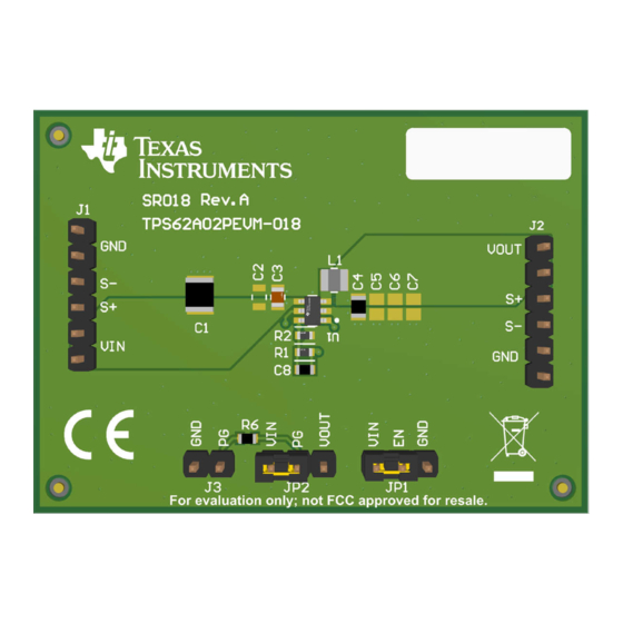
Page 5: Pcb Layouts
This section provides the board layout and illustrations of TPS62A0xPEVM-018 and TPS62A0xAPEVM-018. Figure 4-2. Top-Layer Composite Figure 4-3. Top-Layer Figure 4-4. Bottom-Layer SLUUCV1 – NOVEMBER 2023 TPS62A0xPEVM-018 and TPS62A0xAPEVM-018 Evaluation Modules Submit Document Feedback Copyright © 2023 Texas Instruments Incorporated... - Page 6 2.9 x 2.8 mm TPS62A01APDDCR 1(SR-004) PWM operation C8 is feedforward capacitor which is optional. Device is fully functional without C8 also. TPS62A0xPEVM-018 and TPS62A0xAPEVM-018 Evaluation Modules SLUUCV1 – NOVEMBER 2023 Submit Document Feedback Copyright © 2023 Texas Instruments Incorporated...
- Page 7 Additional Information 5 Additional Information Trademarks All trademarks are the property of their respective owners. SLUUCV1 – NOVEMBER 2023 TPS62A0xPEVM-018 and TPS62A0xAPEVM-018 Evaluation Modules Submit Document Feedback Copyright © 2023 Texas Instruments Incorporated...
- Page 8 STANDARD TERMS FOR EVALUATION MODULES Delivery: TI delivers TI evaluation boards, kits, or modules, including any accompanying demonstration software, components, and/or documentation which may be provided together or separately (collectively, an “EVM” or “EVMs”) to the User (“User”) in accordance with the terms set forth herein.
- Page 9 www.ti.com Regulatory Notices: 3.1 United States 3.1.1 Notice applicable to EVMs not FCC-Approved: FCC NOTICE: This kit is designed to allow product developers to evaluate electronic components, circuitry, or software associated with the kit to determine whether to incorporate such items in a finished product and software developers to write software applications for use with the end product.
- Page 10 www.ti.com Concernant les EVMs avec antennes détachables Conformément à la réglementation d'Industrie Canada, le présent émetteur radio peut fonctionner avec une antenne d'un type et d'un gain maximal (ou inférieur) approuvé pour l'émetteur par Industrie Canada. Dans le but de réduire les risques de brouillage radioélectrique à...
- Page 11 www.ti.com EVM Use Restrictions and Warnings: 4.1 EVMS ARE NOT FOR USE IN FUNCTIONAL SAFETY AND/OR SAFETY CRITICAL EVALUATIONS, INCLUDING BUT NOT LIMITED TO EVALUATIONS OF LIFE SUPPORT APPLICATIONS. 4.2 User must read and apply the user guide and other available documentation provided by TI regarding the EVM prior to handling or using the EVM, including without limitation any warning or restriction notices.
- Page 12 Notwithstanding the foregoing, any judgment may be enforced in any United States or foreign court, and TI may seek injunctive relief in any United States or foreign court. Mailing Address: Texas Instruments, Post Office Box 655303, Dallas, Texas 75265 Copyright © 2023, Texas Instruments Incorporated...
-
Page 13: Important Notice
TI products. TI’s provision of these resources does not expand or otherwise alter TI’s applicable warranties or warranty disclaimers for TI products. TI objects to and rejects any additional or different terms you may have proposed. IMPORTANT NOTICE Mailing Address: Texas Instruments, Post Office Box 655303, Dallas, Texas 75265 Copyright © 2023, Texas Instruments Incorporated...
Need help?
Do you have a question about the TPS62A0 PEVM-018 Series and is the answer not in the manual?
Questions and answers