Lennox ML193DFE Series Unit Information
Hide thumbs
Also See for ML193DFE Series:
- Installation instructions manual (48 pages) ,
- User's information manual (7 pages) ,
- Installation instructions manual (11 pages)
Table of Contents
Advertisement
Quick Links
S e r v i c e L i t e r a t u r e
ML193DFE series units are high-efficiency gas furnaces
manufactured with Lennox DuralokPlus aluminized steel
clamshell-type heat exch angers, with a stainless steel
condensing coil. ML193DFE units are available in heating
input capacities of 44,000 to 88, 000 Btuh and cooling ap-
plications from 1.5 to 4 tons.
Refer to Engineering Handbook for proper sizing.
Units are factory equipped for use with natural gas. A kit
is available for conversion to LPG operation. All ML193D-
FE units are equipped with a hot surface ignition system.
The gas valve is redundant to assure safety shut-off as
required by C.S.A.
The heat exchanger, burners and manifold assembly can
be removed for inspection and service. The maintenance
section gives a detailed description on how this is done.
The ML193DFE can be "twinned" with a second unit. See
twinning kit 16W72 for information for two units to operate
as one, in a shared duct system controlled by a single
thermostat.
All specifications are subject to change. Procedures out-
lined in this manual are presented as a recommendation
only and do not supersede or replace local or state codes.
WARNING
Electric shock hazard. Can cause injury
or death. Before attempting to perform
any service or maintenance, turn the
electrical power to unit OFF at disconnect
switch(es). Unit may have multiple power
supplies.
Table of Contents
Specifications . . . . . . . . . . . . . . . . . . . . . . . . . . . . . . . . . 2
. . . . . . . . . . . . . . . . . . . . . . . . . . 3
I-Unit Components . . . . . . . . . . . . . . . . . . . . . . . . . . . . 6
II Placement and Installation . . . . . . . . . . . . . . . . . . . . 20
III-Start-Up . . . . . . . . . . . . . . . . . . . . . . . . . . . . . . . . . . . 39
IV-Heating System Service Checks . . . . . . . . . . . . . . 40
V-Typical Operating Conditions . . . . . . . . . . . . . . . . . 44
VI-Maintenance . . . . . . . . . . . . . . . . . . . . . . . . . . . . . . . 45
UNIT INFORMATION
UNIT INFORMATION
ML193DFE SERIES UNITS
. . . . . . . . . . . . . . . . . . . . . . 4
. . . . . . . . . . . 48
Corp 1906-L1
Revised 08/2022
Improper installation, adjustment, alteration, service
or maintenance can cause property damage,
personal injury or loss of life. Installation and service
must be performed by a licensed professional HVAC
instale (or equivalent), service agency or the gas
supplier.
As with any mechanical equipment, contact with
sharp sheet metal edges can result in personal
injury. Take care while handling this equipment and
wear gloves and protective clothing.
Page 1
ML193DFE
WARNING
CAUTION
©2016 Lennox Industries, Inc.
Advertisement
Table of Contents

Subscribe to Our Youtube Channel
Related Manuals for Lennox ML193DFE Series


Summary of Contents for Lennox ML193DFE Series
-
Page 1: Table Of Contents
S e r v i c e L i t e r a t u r e Revised 08/2022 ML193DFE SERIES UNITS ML193DFE series units are high-efficiency gas furnaces manufactured with Lennox DuralokPlus aluminized steel clamshell-type heat exch angers, with a stainless steel condensing coil. -
Page 2: Specifications
SPECIFI CAT IONS Model No. ML196DF045XE36B ML196DF070XE48B ML196DF090XE48C ML196DF110XE60C Heating AFUE Performance Input - Btuh 44,000 66,000 88,000 110,000 Output - Btuh 42,000 64,000 86,000 108,000 Temperature rise range - °F 30 - 60 35 - 65 50 - 80 40 - 70 Gas Manifold Pressure (in. -
Page 3: Optional Accessories
O PTI ONAL A CCE SSORIES “B” Width Models “C” Width Models CABINET ACCESSORIES Downflow Combustible Flooring Base 11M60 11M61 CONDENSATE DRAIN KITS Condensate Drain Heat Cable 6 ft. 26K68 26K68 24 ft. 26K69 26K69 Crawl Space Vent Drain Kit 51W18 51W18 15Z70... -
Page 4: Blower Performance Data
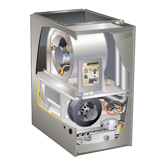
BLO WER D ATA ML196DF045XE36B PERFORMANCE (Less Filter) Air Volume / Watts at Various Blower Speeds External High Medium-High Medium Medium-Low Static (Black) (Brown) (Blue) (Yellow) (Red) Pressure in. w.g. Watts Watts Watts Watts Watts 0.00 1455 1275 1175 0.10 1425 1250 1145... - Page 5 PARTS ARRANGEMENT CONTROL BOX (Includes integrated control, transformer, circuit breaker and door switch) BLOWER MOTOR (hidden) BAG ASSEMBLY (shipping location) Exhaust Intake BLOWER ACCESS PANEL COMBUSTION AIR INDUCER BLOWER DECK DuralokPlus HEAT EXCHANGER ASSEMBLY BURNER ACCESS PANEL COLD END HEADER BOX PRIMARY LIMIT BURNER BOX ASSEMBLY (includes sensor, rollout switches and ignitor)
-
Page 6: I-Unit Components
I-UNIT COMPONENTS 3. Circuit Breaker (CB8) A 24V circuit breaker is also located in the control box. The ELECTROSTATIC DISCHARGE (ESD) switch provides overcurrent protection to the transform- Precautions and Procedures er (T1). The breaker is rated at 3A at 32V. If the current CAUTION exceeds this limit the breaker will trip and all unit opera- tion will shutdown. - Page 7 TABLE 3 1/4” Quick Connect Terminals 120HUM Humidifier 120VAC LINE 120VAC XFMR Transformer 120VAC CIRC Indoor blower 120VAC Indoor air quality accessory 120VAC NEUTRALS Common 120VAC HUM24 Humidifier 24VAC 3/16” Quick Connect Terminals COOL Cooling tap 24VAC HEAT Heating tap 24VAC Continuous blower 24 VAC PARK Park terminal for speed taps...
- Page 8 Fan Time Control IGNITION CONTROL 103217-03 Ignition Control 103217-03 Heating Fan On Time The fan on time of 30 seconds is not adjustable. Heating Fan Off Time Fan off time (time that the blower operates after the heat demand has been satisfied) can be adjusted by moving the jumper to a different setting.
- Page 9 TABLE 5 Ignition Control 107163-01 RED LED Flash Code Diagnostic Codes / Status of Furnace No Power to Control or Board Fault Detected Board Fault Detected Fast Heartbeat Call for Heat / Burner Operation Slow Heartbeat Normal Operation – Idle, Continuous Fan, or Cool 1 Flash Reverse Line Voltage Polarity or Phasing of 120V power 2 Flashes...
- Page 10 B-Heating Components Combustion air inducer (B6), primary limit control (S10), SureLight ignitor, burners, flame rollout switch (S47), gas valve (GV1), combustion air prove switch (S18), and clam- shell heat exchangers are located in the heating compart- ment. The heating compartment can be accessed by re- moving the burner access panel.
- Page 11 1. Flame Rollout Switches (FIGURE 7) 4. Gas Valve (GV1) Flame rollout switches S47 are SPST N.C. high tempera- The ML193DFE uses an internally redundant to valve to turelimits located on the top left and bottom right of the assure safety shut-off. If the gas valve must be replaced, front burner box plate.
- Page 12 To Measure Flame Signal - Integrated Control: 4 - Connect (-) lead to flame sensor wire. 5 - Connect (+) lead to Terminal FS on integrated Use a digital readout meter capable of reading DC micro- control. amps. See FIGURE 10 for flame signal check. 6 - Turn supply voltage on and close thermostat 1 - Set the meter to the DC amps scale.
- Page 13 Test 1 Check ignitor circuit for correct resistance. Remove 4-pin plug from control. Check ohms reading across terminals 2 and 4. Reading should be between 39 and 70 ohms. If value is correct, this is the only test needed. If the reading on the meter is not correct, (0 or infinity) then a second test is needed.
- Page 14 8. Combustion Air Pressure Switch (FIGURE 12) Checks of pressure differential can aid in troubleshoot- ML193DFE series units are equipped with a differential ing. When measuring the pressure differential, readings pressure switch located on the cold end header box. The should be taken at the pressure switch.
- Page 15 Measuring Pressure Differential Red and Black Tubing or Red Tubing (negative −) Black Tubing (positive +) To Cold End Header Box To Cold End Header Box Field Provided Tubing To Pressure Switch “+” High “−” Low Operate unit and observe manometer reading. Remove thermostat demand and allow unit to cycle off.
- Page 16 TABLE 8 Problem Corrective Action Check that the pressure switch is open without the com- Pressure switch stuck closed bustion air inducer operating. Replace if defective. Pressure switch does not close due to obstruction in vent Check for restricted vent. Remove all blockage. Check for pipe.
- Page 17 C-Blower Compartment BLOWER WHEEL REPLACEMENT IMPORTANT Center Blower Wheel in Blower Housing Each blower is statically and dynamically balanced as an assembly before installation in the unit. EL196DFE units are equipped with a constant torque ECM motor. It has a DC motor coupled to an electronic control module both contained in the same motor housing.
- Page 18 Multi−Meter (set to VAC) Multi−Meter (set to VAC) Test 1 Test 3 (if necesssary) Turn on power to unit. Check for 120 volts across terminals Check for 120 volts across terminals “CIRC” and “Neutrals” “L” and “N” on input plug P48. If voltage is present continue on the integrated control.
- Page 19 Replacing the Motor Module Motor Test 1 - Disconnect electrical power to unit. 2 - Remove unit access panel. 3 - Unplug the two harnesses from the motor control module. See FIGURE 18. Unplug the Two Harness Connection TWO HARNESS CONNECTIONS MOTOR MOTOR CONTROL MODULE...
-
Page 20: Placement And Installation
II-PLACEMENT AND INSTALLATION IMPORTANT Pipe & Fittings Specifications Exhaust and intake connections are made of PVC. All pipe, fittings, primer and solvent cement must conform Use PVC primer and solvent cement when using with American National Standard Institute and the Ameri- PVC vent pipe. - Page 21 TABLE 11 OUTDOOR TERMINATION USAGE* STANDARD CONCENTRIC Flush Mount Wall Kit 1-1/2 inch 2 inch 3 inch Vent Pipe Input Size 2 inch 3 inch Field Dia. in. 71M80 (US) 69M29 (US) 60L46 (US) Fabricated 51W11 (US) 22G44 (US) 44W92 44W92 444W93 44J40 (US)
- Page 22 Joint Cementing Procedure Venting Pratices All cementing of joints should be done according to the specifications outlined in ASTM D 2855. Piping Suspension Guidelines NOTE - A sheet metal screw may be used to secure the SCHEDULE 40 intake pipe to the connector, if desired. Use a drill or self PVC - 5' tapping screw to make a pilot hole.
- Page 23 1 - - Seal any unused openings in the common venting Vent Piping Guidelines system. NOTE - Lennox has approved the use of DuraVent® and 2 - Inspect the venting system for proper size and Centrotherm manufactured vent pipe and terminations horizontal pitch.
- Page 24 In some applications which permit the use of several dif- Intake or exhaust? ferent sizes of vent pipe, a combination vent pipe may be used. Contact Lennox’ Application Department for assis- How many elbows? tance in sizing vent pipe in these applications. Count all elbows inside CAUTION and outside house.
- Page 25 TABLE 13 Maximum Allowable Intake or Exhaust Vent Length in Feet *Size intake and exhaust pipe length separately. Values in table are for Intake OR Exhaust, not combined total. Both Intake and Exhaust must be same pipe size. NOTE - Additional vent pipe and elbows used to terminate the vent pipe outside the structure must be included in the total vent length calculation. Standard Termination at Elevation 0 - 10,000 ft.
- Page 26 TYPICAL EXHAUST PIPE CONNECTIONS 045/070 Only 2” 1−1/2” 2” 2” 2” TRANSITION 2” 2” Exhaust Exhaust 3” DO NOT transition from larger to smaller pipe in horizontal runs TRANSITION of exhaust pipe. INTAKE EXHAUST DO NOT transition from smaller *2” to larger pipe size in horizontal TOP VIEW runs of exhaust pipe.
- Page 27 Intake Piping CAUTION The ML193DFE furnace may be installed in either direct If this unit is being installed in an application with vent or non-direct vent applications. In non-direct vent ap- combustion air coming in from a space serviced by plications, when intake air will be drawn into the furnace an exhaust fan, power exhaust fan, or other device from the surrounding space, the indoor air quality must be...
- Page 28 General Guidelines for Vent Terminations NOTE - See TABLE 15 for maximum allowed exhaust pipe length without insulation in unconditioned space during In Non-Direct Vent applications, combustion air is taken winter design temperatures below 32°F (0°C). If required from indoors and the flue gases are discharged to the out- exhaust pipe should be insulated with 1/2”...
- Page 29 Conditioned Space Exhaust Pipe Pipe Insulation Intake Conditioned Pipe Unconditioned Space Space FIGURE 30 Page 29...
- Page 30 ‡ Permitted only if veranda, porch, deck or balcony is fully open NOTE - This figure is intended to illustrate clearance on a minimum of two sides beneath the floor. Lennox recommends requirement and does not serve as a substitute for avoiding this location if possible.
- Page 31 ‡ Permitted only if veranda, porch, deck or balcony is fully open on a minimum of locally adopted installation codes. two sides beneath the floor. Lennox recommends avoiding this location if possible. FIGURE 32 Page 31...
- Page 32 Details of Intake and Exhaust Piping Terminations for NOTE - Care must be taken to avoid recirculation of Direct Vent Installations exhaust back into intake pipe. 6 - On field supplied terminations, a minimum distance NOTE - In Direct Vent installations, combustion air is taken between the end of the exhaust pipe and the end of from outdoors and flue gases are discharged to outdoors.
- Page 33 7 - - If intake and exhaust piping must be run up a side wall to position above snow accumulation or other obstructions, iping must be supported. At least 12” EXHAUST one bracket must be used within 6” from the top of (305mm) VENT 5-1/2”...
- Page 34 FIELD FABRICATED WALL TERMINATION NOTE − FIELD−PROVIDED REDUCER MAY BE 2” (51mm) 3” (76mm) REQUIRED TO ADAPT Vent Pipe Vent Pipe LARGER VENT PIPE SIZE TO TERMINATION A− Minimum clearance above grade or average 12” (305 mm) 12” (305 mm) snow accumulation B−...
- Page 35 2 - On field supplied terminations for side wall exit, DIRECT VENT APPLICATION exhaust piping may extend a maximum of 12 inches USING EXISTING CHIMNEY STRAIGHT-CUT OR (305mm) for 2” PVC and 20 inches (508mm) for 3” ANGLE-CUT IN DIRECTION OF ROOF SLOPE * (76mm) PVC beyond the outside wall.
- Page 36 If this is not possi- ble, a heat cable kit may be used on the condensate trap and line. Heat cable kit is available from Lennox in various lengths; 6 ft. (1.8m) - kit no. 26K68 and 24 ft. (7.3m) - kit FIGURE 44 no.
- Page 37 IMPORTANT Condensate Trap With Optional Overflow Switch From Evaporator Coil When combining the furnace and evaporator coil drains together, the A/C condensate drain outlet HorizontalFurnace4” Min. to 5” Max.above condensatedrain connection) must be vented to relieve pressure in order for the furnace pressure switch to operate properly.
- Page 38 TRAP / DRAIN ASSEMBLY USING 1/2” PVC OR 3/4” PVC Optional Condensate Drain Connection Adapter 3/4 inch slip X 3/4 inch mpt (not furnished) 90° Street Elbow 3/4 inch PVC (not furnished) Adapter 3/4 inch slip X 3/4 inch mpt (not furnished) Condensate Drain Connection In Unit 1 (25 mm) Min.
-
Page 39: Iii-Start-Up
III-START-UP 2 - Set the thermostat to the lowest setting. 3 - Turn off all electrical power to the unit. A-Preliminary and Seasonal Checks 4 - This furnace is equipped with an ignition device 1 - Inspect electrical wiring, both field and factory which automatically lights the burners. -
Page 40: Iv-Heating System Service Checks
Use of a specialty Gas Leak Detector is strongly recom- All units are C.S.A. design certified without modifications. mended. It is available through Lennox under part number Refer to the ML193DFE Operation and Installation In- 31B2001. See Corp. 8411-L10, for further details. - Page 41 Negative Barbed Fitting (remove for manifold adjustment) (−) 2” Long Square Tubing (remove for manifold adjustment) Manifold Pressure Outlet Gas Valve Regulator Vent Hose (to burner box) Barbed Fitting 10” Long Square Tubing Measuring Device FIGURE 53 Page 41...
- Page 42 F- Proper Gas Flow (Approximate) G- Proper Combustion Furnace should operate at least 15 minutes with correct TABLE 17 manifold pressure and gas flow rate before checking com- GAS METER CLOCKING CHART bustions. Take sample beyond the flue outlet and compare Seconds For One Revolution to TABLE 18.
- Page 43 I- Proper Ground and Voltage 2 - In addition, measure the AC voltage from Line Hot to Line Neutral (spade terminals) on the integrated A poorly grounded furnace can contribute to premature control. See FIGURE 54. This voltage should be in ignitor failure.
-
Page 44: V-Typical Operating Conditions
V-TYPICAL OPERATING CHARACTERISTICS C-External Static Pressure 1 - Tap locations shown in FIGURE 56. A-Blower Operation and Adjustment1 2 - Punch a 1/4” diameter hole in supply and return NOTE- The following is a generalized procedure and does air plenums. Insert manometer hose flush with inside edge of hole or insulation. -
Page 45: Vi-Maintenance
3 - Inspect screen and rinse with tap water if needed. the data given in the appropriate Lennox Product 4 - Reinstall screen and turn on power to unit. Specifications bulletin. Additional information is provided in Service and Application Note ACC002 (August 2000). - Page 46 16 - Remove screws along vestibule sides and bottom Condensate Hose Screen which secure vestibule panel and heat exchanger assembly to cabinet. Remove two screws from blower rail which secure bottom heat exchanger flange. Remove heat exchanger from furnace cabinet. 17 - Back wash heat exchanger with soapy water solution or steam.
- Page 47 Cleaning the Burner Assembly 8 - Reconnect the sensor wire and reconnect the 2-pin plug to the ignitor wiring harness. 1 - Turn off electrical and gas power supplies to furnace. 9 - Reinstall the burner box assembly using the existing Remove upper and lower furnace access panels.
-
Page 48: Vii-Wiring And Sequence Of Operation
1 - When there is a call for heat, W1 of the thermostat 5 - Gas valve opens for a 4-second trial for ignition energizes W of the furnace control with 24VAC. 6 - Flame is sensed, gas valve remains open for the 2 - S10 primary limit switch and S47 rollout switch are heat call. - Page 49 Troubleshooting: Heating Sequence of Operation HEATING SEQUENCE OF OPERATION ABNORMAL HEATING MODE NORMAL HEATING MODE POWER ON GAS VALVE OFF. COMBUSTION AIR INDUCER OFF. INDOOR BLOWER DELAY OFF. CONTROL SELF-CHECK OKAY? LED SLOW FLASH (RESET CONTROL BY TURNING MAIN POWER OFF.) LED FLASHES CODE 1 - POLARITY REVERSED.
- Page 50 Troubleshooting: Heating Sequence of Operation (Continued) HEATING SEQUENCE CONTINUED 15 SECOND COMBUSTION AIR INDUCER PREPURGE INITIATED BY CLOSED PRESSURE SWITCH. LED FLASHES CODE 13 - LOW LINE VOLTAGE. ONCE VOLTAGE IS ABOVE IS VOLTAGE ABOVE 70 VOLTS? IGNITOR WARM UP -- 20 SECONDS. 75 VOLTS, HEATING SEQUENCE RESTARTS.
- Page 51 Troubleshooting: Cooling Sequence of Operation COOLING SEQUENCE OF OPERATION POWER ON IGNITION CONTROL MAIN POWER ON. GAS VALVE OFF. COMBUSTION AIR INDUCER OFF. INDOOR BLOWER OFF WITH NORMAL DELAY. CONTROL SELF DIAGNOSTIC CHECK. SIGNAL CIRCUIT BOARD FAILURE AT LED. IS CONTROL OPERATING NORMALLY? INTERRUPT MAIN POWER TO RESET CONTROL.
- Page 52 Troubleshooting: Continuous Fan / Accessories Sequence of Operation CONTINUOUS FAN SEQUENCE OF OPERATION LED: SLOW FLASH RATE REMAINS UNCHANGED THROUGHOUT SEQUENCE. MANUAL FAN SELECTION MADE AT THERMOSTAT. CONTROL (G) ENERGIZES SYSTEM FAN AT FAN SPEED. EAC TERMINAL IS ENERGIZED. THERMOSTAT CALLS FOR HEAT (W). SYSTEM FAN CONTINUES FAN SPEED WITHOUT THERMOSTAT CALLS FOR COOLING.
Need help?
Do you have a question about the ML193DFE Series and is the answer not in the manual?
Questions and answers