Lennox ML193UH Installation Instructions Manual
Merit series gas furnace upflow / horizontal air discharge
Hide thumbs
Also See for ML193UH:
- Installation instructions manual (51 pages) ,
- Instruction manual (20 pages) ,
- User's information manual (8 pages)
Table of Contents
Advertisement
E 2013 Lennox Industries Inc.
Dallas, Texas, USA
HORIZONTAL LEFT
. . . . . . . . . . . . . . . . . . . . . . . . . . . . . . . .
. . . . . . . . . . . . . . . . . . . . . . . . . .
. . . . . . . . . . . . . . . . . . . . . . . . . . . . . . .
. . . . . . . . . . . . . . . . . . . . . . . . . . . . . . . . . . . . . . . .
. . . . . . . . . . . . . . . . . . . . . . . . . . . . . . .
. . . . . . . . . . . . . . . . . . . . . . . . . . . . . . . . . . . . . . . . . .
. . . . . . . . . . . . . . . . . . . . . . . . . . . . . . . . . . . .
. . . . . . . . . . . . . . . . . . . . . . . . . . . . . . .
08/13
*2P0813*
AIR FLOW
UPFLOW
HORIZONTAL RIGHT
Table of Contents
. . . . . . . . . . . . . . . . . . . . . . . .
. . . . . . . . . . .
. . . . . . . . . . . . . . .
. . . . . . . . . . . . . . . . . . .
. . . . . . . . . . . . . . . . . . . . . . .
INSTALLATION
INSTRUCTIONS
ML193UH
®
MERIT
SERIES GAS FURNACE
UPFLOW / HORIZONTAL AIR DISCHARGE
507121-01
08/2013
Supersedes 06/2013
THIS MANUAL MUST BE LEFT WITH THE
HOMEOWNER FOR FUTURE REFERENCE
This is a safety alert symbol and should never be ignored.
When you see this symbol on labels or in manuals, be alert
to the potential for personal injury or death.
As with any mechanical equipment, personal injury
can result from contact with sharp sheet metal
edges. Be careful when you handle this equipment.
Improper installation, adjustment, alteration, service
or maintenance can cause property damage, person
al injury or loss of life. Installation and service must
be performed by a licensed professional HVAC in
staller (or equivalent), service agency or the gas sup
plier.
2
. . . . . . . . . . . . . . . . . . . . . . . . . . . . . . . . . . . . .
3
. . . . . . . . . . . . . . . . . . . . . . . . . . . . . . . . . . . . . . .
3
3
. . . . . . . . . . . . . . . . . . . . . . . . . . . . . . . . . . . .
4
5
5
. . . . . . . . . . . . . . . . . . . . . . . . . . . . . . . . . . . .
8
13
13
13
. . . . . . . . . . . . . . . . . . . . . . . . . . . . . . . . . . . . . . . .
15
16
Page 1
CAUTION
WARNING
. . . . . . . . . . . . . . . . . . . . . . . . . . .
. . . . . . . . . . . . . . . . . . . . . . . . . . . . . . .
. . . . . . . . . . . . . . . . . . . . . .
. . . . . . . . . . . . . . . . . . . . . . . . . . . . . .
. . . . . . . . . . . . . . . . . . . . . . . . . .
. . . . . . . . . . . . . . . . . . . . . . . . . .
. . . . . . . . . . . . . . . . . . . . . . . . . . . . . . . .
. . . . . . . . . . . . . . . . . . . . . . . . . . . . . . .
507121-01
*P507121-01*
Litho U.S.A.
17
34
37
39
40
41
42
42
. . . . . . .
44
45
45
46
47
48
Advertisement
Table of Contents

Subscribe to Our Youtube Channel
Related Manuals for Lennox ML193UH


Summary of Contents for Lennox ML193UH
-
Page 1: Table Of Contents
INSTALLATION INSTRUCTIONS E 2013 Lennox Industries Inc. Dallas, Texas, USA ML193UH ® MERIT SERIES GAS FURNACE UPFLOW / HORIZONTAL AIR DISCHARGE 507121-01 Litho U.S.A. 08/2013 Supersedes 06/2013 THIS MANUAL MUST BE LEFT WITH THE HOMEOWNER FOR FUTURE REFERENCE This is a safety alert symbol and should never be ignored. -
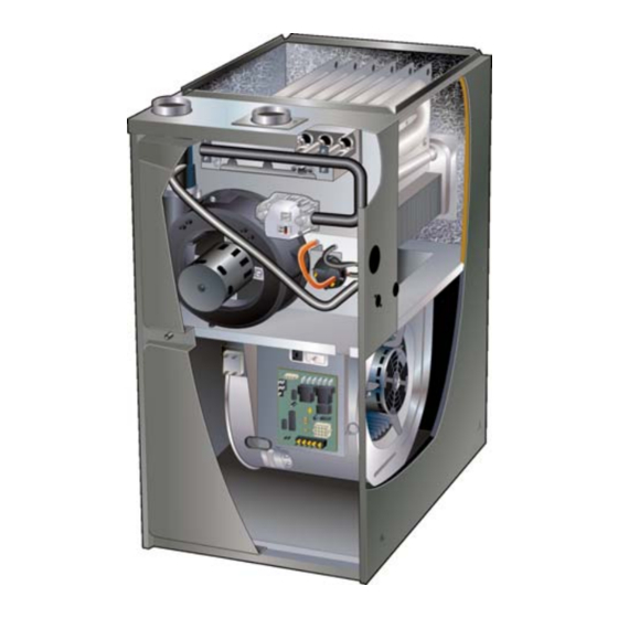
Page 2: Unit Dimensions
ML193UH Unit Dimensions - inches (mm) EXHAUST AIR NOTE − 60C and 60D size units that require air 3−3/8 OUTLET volumes 1800 cfm or over (850 L/s) must have (86) one of the following 1. Single side return air with transition, to accommodate 2 (51) 20 x 25 x 1 in. -
Page 3: Ml193Uh Gas Furnace
1 - Snap bushing zontal or upflow applications with bottom return air. 1 - Snap plug The ML193UH can be installed as either a Direct Vent 1 - Wire tie or a Non-Direct Vent gas central furnace. 1 - Condensate trap The furnace is equipped for installation in natural gas ap... -
Page 4: Use Of Furnace As Construction Heater
This furnace design has not been CSA certified for installa ture heat exchanger failure. tion in mobile homes, recreational vehicles, or outdoors. This ML193UH furnace must be installed so that its electri Use of Furnace as Construction Heater cal components are protected from water. -
Page 5: General
This could cause improper combustion Combustion, Dilution & Ventilation Air and unsafe operation. If the ML193UH is installed as a Non-Direct Vent Fur • When the furnace is installed in non-direct vent applica nace, follow the guidelines in this section. - Page 6 A confined space is an area with a volume less than 50 cu this section to install ML193UH furnaces to ensure efficient bic feet (1.42 m ) per 1,000 Btu (.29 kW) per hour of the and safe operation.
- Page 7 Air from Outside EQUIPMENT IN CONFINED SPACE If air from outside is brought in for combustion and ventila (Inlet Air from Ventilated Crawlspace and Outlet Air to Outside) tion, the confined space shall be provided with two perma nent openings. One opening shall be within 12” (305mm) of the top of the enclosure and one within 12”...
- Page 8 LOCATION) Upflow Applications NOTE-Each air duct opening shall have a free area of at least one The ML193UH gas furnace can be installed as shipped in square inch per 2,000 Btu (645mm per .59kW) per hour of the total input rating of all equipment in the enclosure. If the equipment room the upflow position.
-
Page 9: Setting Equipment
SETTING EQUIPMENT UPFLOW APPLICA TION UNIT UNIT FRONT FRONT AIR FLOW AIR FLOW 1/2” max. FRONT VIEW SIDE VIEW SIDE VIEW HORIZONTAL APPLICATION UNIT FRONT AIR FLOW 1/2” max. END VIEW FRONT VIEW Unit must be level side-to-side. Unit may be positioned from level to 1/2” toward the front to aid in draining. FIGURE 11 Page 9... - Page 10 Fire, explo ML193UH applications which include side return air sion, carbon monoxide poisoning, personal injury and a condensate trap installed on the same side of the and/or property damage could result.
- Page 11 Optional Return Air Base CONDENSATE (Upflow Applications Only) TRAP FURNACE FRONT IF BASE 23 (584) 3−1/4 IS USED Overall (83) (Maximum) WITHOUT Minimum IAQ CABINET, 11 (279) INDOOR AIR A SINGLE Maximum 22−7/16 QUALITY RETURN AIR Unit side return air 14 (356) (570) CABINET...
- Page 12 The ML193UH furnace can be installed in horizontal ap HORIZONTAL SUSPENSION KIT plications with either right- or left-hand air discharge. Refer to figure 17 for clearances in horizontal applications. Internal Brace Metal Strap (provided with kit) (typical) Horizontal Application Installation Clearances...
-
Page 13: Filters
Before using any filter with this system, check the to fit the filter frame. specifications provided by the filter manufacturer against the data given in the appropriate Lennox Pipe & Fittings Specifications Product Specifications bulletin. Additional informa tion is provided in Service and Application Note All pipe, fittings, primer and solvent cement must conform ACC002 (August 2000). - Page 14 CAUTION IMPORTANT Solvent cements for plastic pipe are flammable liq ML193UH exhaust and intake connections are made uids and should be kept away from all sources of of PVC. Use PVC primer and solvent cement when ignition. Do not use excessive amounts of solvent using PVC vent pipe.
-
Page 15: Joint Cementing Procedure
TABLE 3 OUTDOOR TERMINATION USAGE* STANDARD CONCENTRIC Flush Wall Kit Wall Ring Kit 1-1/2 inch 2 inch 3 inch Mount Vent 2 inch 3 inch 2 inch Pipe Input Size Field Dia. in. 51W11 71M80 69M29 Fabricated 44J40 (US) 22G44 (US) (US) (US) 60L46 (US) -
Page 16: Venting Practices
Room) Piping Suspension Guidelines SCHEDULE 40 PVC - 5' If an ML193UH furnace replaces a furnace which all other pipe* - 3' was commonly vented with another gas appliance, the size of the existing vent pipe for that gas ap... -
Page 17: Vent Piping Guidelines
Use the following steps to correctly size vent pipe diameter. Vent Piping Guidelines The ML193UH can be installed as either a Non-Direct Vent or a Direct Vent gas central furnace. Piping Size Process NOTE - In Non‐Direct Vent installations, combustion air is taken from indoors and flue gases are discharged out... - Page 18 TABLE 5 Maximum Allowable Intake or Exhaust Vent Length in Feet NOTE - Size intake and exhaust pipe length separately. Values in table are for Intake OR Exhaust, not combined total. Both Intake and Exhaust must be same pipe size. NOTE - Additional vent pipe and elbows used to terminate the vent pipe outside the structure must be included in the total vent length calculation.
- Page 19 TYPICAL EXHAUST PIPE CONNECTIONS IN UPFLOW DIRECT OR NON-DIRECT VENT APPLICATIONS Pipe size determined in table 5 2” 3” 2” 2” 2” 2” TRANSITION EXHAUST *2” DO NOT transition from smaller to larger pipe in horizontal runs of exhaust pipe. * When transitioning up in pipe size, use the shortest length of 2”...
- Page 20 TYPICAL AIR INTAKE PIPE CONNECTIONS IN UPFLOW DIRECT VENT APPLICATIONS Pipe size determined in table 5 2” 3” TRANSITION 2” AIR INTAKE *2” 2” 2” 2” * When transitioning up in pipe size, use the shortest length of 2” PVC pipe possible. NOTE −...
- Page 21 Intake Piping TYPICAL AIR INTAKE PIPE CONNECTIONS The ML193UH furnace may be installed in either direct HORIZONTAL NON−DIRECT VENT APPLICATIONS vent or non-direct vent applications. In non-direct vent (Horizontal Right−Hand Air Discharge Application Shown) applications, when intake air will be drawn into the furnace...
- Page 22 The ML193UH is then classified as a direct vent, maximum volume of combustion air required for Category IV gas furnace.
- Page 23 TABLE 7 Maximum Allowable Exhaust Vent Pipe Length (in ft.) Without Insulation In Unconditioned Space For Winter Design Temperatures Single - Stage High Efficiency Furnace Unit Input Size Winter Design Vent Pipe Temperatures °F (°C) Diameter 2 in. 32 to 21 (0 to -6) 2-1/2 in.
-
Page 24: Vent Termination Clearances
‡ Permitted only if veranda, porch, deck or balcony is fully open on a minimum of two sides beneath the floor. Lennox recommends avoiding this location if possible. FIGURE 33... - Page 25 ‡ Permitted only if veranda, porch, deck or balcony is fully open on a minimum of two sides beneath the floor. Lennox recommends avoiding this location if possible. FIGURE 34 Page 25...
- Page 26 2” (51mm) used and the flue gasses may impinge on the building ma *ML193UH-045, -070 and -090 units with the flush mount termination terial, a corrosion-resistant shield (minimum 24 inches must use the 1-1/2” accelerator supplied with the kit unless a tee is used square) should be used to protect the wall surface.
- Page 27 7 - If intake and exhaust piping must be run up a side wall to position above snow accumulation or other ob structions, piping must be supported. At least one 12” EXHAUST (305mm) bracket must be used within 6” from the top of the el VENT 5-1/2”...
- Page 28 FIELD FABRICATED WALL TERMINATION NOTE − FIELD−PROVIDED REDUCER MAY BE 2” (51mm) 3” (76mm) REQUIRED TO ADAPT LARGER VENT PIPE SIZE Vent Pipe Vent Pipe TO TERMINATION A− Minimum clearance above grade or average 12” (305 mm) 12” (305 mm) snow accumulation B−...
- Page 29 ML193UH DIRECT VENT APPLICATION SIZE TERMINATION PIPE PER TABLE 8. 12” (305mm) USING EXISTING CHIMNEY ABOVE AVE. SNOW STRAIGHT-CUT OR ANGLE-CUT IN DIRECTION ACCUMULATION 3”-8” OF ROOF SLOPE * (76mm-203mm) 8” - 12” (203mm - 305mm) 3” (76mm) OR UNCONDITIONED 2”...
- Page 30 Heating cable kit is sate line from the furnace and evaporator coil can available from Lennox in various lengths; 6 ft. (1.8m) - drain together. See figures 50, 52 and 53. kit no. 26K68; 24 ft. (7.3m) - kit no. 26K69; and 50 ft.
- Page 31 T o Drai n *Piping from furnace must slope down a minimum of 1/4” per ft. toward trap. FIGURE 50 FIGURE 48 ML193UH With Evaporator Coil Using A Separate Drain Evaporator drain line required (Trap at coil is optional) Field Provided Vent (1”...
- Page 32 ML193UH with Evaporator Coil Using a Separate Drain (Unit shown in horizontal left-hand discharge position) Field Provided Vent Evaporator (4” min. to 5” max. above Coil condensate connection) 4”min 5”max 5’ max. PVC Pipe Only Condensate Drain Connection (Trap at coil is optional)
- Page 33 TRAP / DRAIN ASSEMBLY USING 1/2” PVC OR 3/4” PVC Optional Condensate Drain Connection Adapter 3/4 inch slip X 3/4 inch mpt (not furnished) 90° Street Elbow 3/4 inch PVC (not furnished) Adapter 3/4 inch slip X 3/4 inch mpt (not furnished) Condensate Drain Connection In Unit 1 (25 mm) Min.
-
Page 34: Gas Piping
4 - Piping should be sloped 1/4 inch per 15 feet (6mm per Gas Piping 5.6m) upward toward the gas meter from the furnace. The piping must be supported at proper intervals, ev ery 8 to 10 feet (2.44 to 3.05m), using suitable hangers CAUTION or straps. - Page 35 Left Side Piping Right Side Piping AUTOMATIC GAS VALVE (Standard) (Alternate) (with manual shut-off valve) Bellows Grommet MANUAL MAIN SHUT-OFF MANUAL VALVE Plug Plug MAIN SHUT-OFF VALVE GROUND GROUND JOINT JOINT UNION UNION DRIP LEG Gas Valve Gas Valve Bellows Grommet DRIP LEG FIELD PROVIDED...
- Page 36 TABLE 9 GAS PIPE CAPACITY - FT /HR (kL/HR) Length of Pipe-Feet(m) Nominal Internal Iron Pipe Size Diameter -Inches(mm) -Inches(mm) (3.048) (6.096) (9.144) (12.192) (15.240) (18.288) (21.336) (24.384) (27.432) (30.480) .622 (12.7) (17.799) (4.96) (3.40) (2.75) (2.32) (2.07) (1.87) (1.73) (1.61) (1.50) (1.42)
-
Page 37: Electrical
2 - When the ML193UH is running in the heating mode, Before connecting the thermostat check to make sure the the indoor blower will run on the heating speed. - Page 38 D Generator should have a wave form distortion of less volts to 132 volts) than 5% THD (total harmonic distortion). D The furnace operates at 60 Hz + 5% (Range: 57 Hz to 63 Hz) TYPICAL ML193UH WIRING DIAGRAM FIGURE 60 Page 38...
-
Page 39: Integrated Control
Integrated Control INTEGRATED CONTROL (Automatic Hot Surface Ignition System) TERMINAL DESIGNATIONS Humidifier (120VAC) Input (120VAC) LINE Transformer (120VAC) XFMR Indoor Air Qality Accessory Air Cleaner (120VAC) Blower - Cooling Speed (120VAC) COOL Blower - Heating Speed (120VAC) HEAT Dead terminals to park alternate spd taps PARK Continuous blower CONT... -
Page 40: Unit Start Up
SCREW some gas is heavier than air and will settle on the floor. The gas valve on the ML193UH is equipped with a gas con trol switch (lever). Use only your hand to move switch. Nev er use tools. If the the switch will not move by hand, do not try to repair it. -
Page 41: Gas Pressure Measurement
4 - Move gas valve switch to OFF. Furnace should operate at least 5 minutes before checking gas flow. Determine time in seconds for two revolutions of 5 - Replace the upper access panel. gas through the meter. (Two revolutions assures a more Failure To Operate accurate time.) Divide by two and compare to time in table If the unit fails to operate, check the following:... -
Page 42: Proper Combustion
Take combustion sample beyond the flue outlet ML193UH units require no manifold pressure adjustments and compare to the tables below. for operation at altitudes up to 10,000 feet (3048 m) above TABLE 12 sea level. - Page 43 Do not operate a summer exhaust fan. After the ML193UH gas furnace has been started, the fol 6 - Follow the lighting instruction to place the appliance lowing test should be conducted to ensure proper venting being inspected into operation.
-
Page 44: Testing For Combustion Air Non-Direct Vents
Other Unit Adjustments HEAT FAN‐OFF TIME IN SECONDS Primary Limit. The primary limit is located on the heating compartment vestibule panel. This limit is factory set and requires no ad justment. NO JUMPER Flame Rollout Switches (Two) To adjust fan-off timing, reposition jumper across pins to These manually reset switches are located on the front of achieve desired setting. -
Page 45: Other Unit Adjustments
”C” and ”Twin” terminals of the two controls. Twinning the ML193UH The 24 VAC secondary of the two systems must be in The control board in this furnace is equipped with a provi phase. All thermostat connections are made to one control sion to ”twin”... -
Page 46: Service
Electrical Service 1 - Check all wiring for loose connections. 2 - Check for the correct voltage at the furnace (furnace operating). WARNING 3 - Check amp-draw on the blower motor. Motor Nameplate__________Actual__________ ELECTRICAL SHOCK, FIRE, Winterizing and Condensate Trap Care OR EXPLOSION HAZARD. -
Page 47: Repair Parts List
Repair Parts List The following repair parts are available through Lennox dealers. When ordering parts, include the complete furnace model number listed on the CSA nameplate -- Example: ML193UH045XP36B-01. All service must be performed by a licensed professional installer (or equivalent), service agency, or gas supplier. -
Page 48: Start Up Checklist
Start-Up & Performance Check List UNIT SET UP Furnace: Model Number_______________ Serial Number_________________ SUPPLY Line Voltage GAS SUPPLY LP Propane Gas Natural Gas Piping Connections Tight Leak Tested Flter Supply Line Pressure “W.C.________ RETURN AIR Gas Supply Pressure DUCT SYS SUPPLY AIR DUCT Sealed Insulated (if necessary) - Page 49 UNIT OPERATION HEATING MODE COOLING MODE GAS MANIFOLD PRESSURE “W.C._____ INDOOR BLOWER AMPS______ COMBUSTION SAMPLE CO CO PPM_______ TEMPERATURE DROP ______ Return Duct Temperature _________ INDOOR BLOWER Supply Duct Temperature _______ AMPS______ Temperature Drop = _________ TEMPERATURE RISE TOTAL EXTERNAL STATIC (dry coil) Supply Duct Temperature ________ Supply External Static _______ Return Duct Temperature...
- Page 50 Requirements for Commonwealth of Massachusetts Modifications to NFPA-54, Chapter 10 4 - INSPECTION. The state or local gas inspector of the side wall, horizontally vented, gas-fueled equipment Revise NFPA-54 section 10.8.3 to add the following re shall not approve the installation unless, upon inspec quirements: tion, the inspector observes carbon monoxide detec...
- Page 51 FOR THE PROVINCE OF ONTARIO, HORIZONTAL SIDEWALL VENT APPLICATIONS ONLY For exterior horizontal venting applications, the 2” X 1.5” plume is unobjectionable. If the installation requires more reducer for 2” venting at the point where the exhaust pipe separation between the flue gases and the building struc exits the structure is not required in direct or nondirect vent ture, a reducer may be installed on the exhaust pipe to in...
Need help?
Do you have a question about the ML193UH and is the answer not in the manual?
Questions and answers