Table of Contents
Advertisement
Service Literature
ML193DF series units are high-efficiency gas furnaces
manufactured with Lennox DuralokPlust aluminized steel
clamshell-type heat exchangers, with a stainless steel con
densing coil. ML193DF units are available in heating input
capacities of 44,000 to 110,000 Btuh (13 to 32.2 kW) and
cooling applications from 2 through 5 tons (7.0 through
17.6 kW). Refer to Engineering Handbook for proper siz
ing.
Units are factory equipped for use with natural gas. A kit is
available for conversion to LPG operation. All ML193DF
units are equipped with a hot surface ignition system. The
gas valve is redundant to assure safety shut-off as required
by C.S.A.
The heat exchanger, burners and manifold assembly can
be removed for inspection and service. The maintenance
section gives a detailed description on how this is done.
All specifications are subject to change. Procedures out
lined in this manual are presented as a recommendation
only and do not supersede or replace local or state codes.
WARNING
Electric shock hazard. Can cause injury
or death. Before attempting to perform
any service or maintenance, turn the
electrical power to unit OFF at discon
nect switch(es). Unit may have multiple
power supplies.
Table of Contents
. . . . . . . . . . . . . . . . . . . . . . . . . . . . . . . . .
. . . . . . . . . . . . . . . . . . . . . . . . . .
. . . . . . . . . . . . . . . . . . . . . . . . . . . .
II Placement and Installation
. . . . . . . . . . . . . . . . . . . . . . . . . . . . . . . . . . .
V-Typical Operating Conditions
. . . . . . . . . . . . . . . . . . . . . . . . . . . . . . .
VII-Wiring and Sequence of Operation
Corp. 1026-L5
Revised 03-2014
ML193DF SERIES UNITS
2
3
. . . . . . . . . . . . . . . . . . . . . .
4
6
. . . . . . . . . . . . . . . . . . . .
18
36
. . . . . . . . . . . . . .
37
. . . . . . . . . . . . . . . . .
39
40
. . . . . . . . . . .
42
WARNING
Improper installation, adjustment, alteration, service
or maintenance can cause property damage, person
al injury or loss of life. Installation and service must
be performed by a licensed professional HVAC in
staller (or equivalent), service agency or the gas sup
plier.
Sharp edges.
Be careful when servicing unit to avoid sharp edges
which may result in personal injury.
Page 1
ML193DF
WARNING
© 2014 Lennox Industries Inc.
Litho U.S.A.
Advertisement
Table of Contents

Related Manuals for Lennox ML193DF045P36B


Summary of Contents for Lennox ML193DF045P36B
-
Page 1: Table Of Contents
Service Literature ML193DF SERIES UNITS ML193DF series units are high-efficiency gas furnaces manufactured with Lennox DuralokPlust aluminized steel clamshell-type heat exchangers, with a stainless steel con densing coil. ML193DF units are available in heating input capacities of 44,000 to 110,000 Btuh (13 to 32.2 kW) and cooling applications from 2 through 5 tons (7.0 through... -
Page 2: Specifications
SPECIFICATIONS Model No. ML193DF045P36B ML193DF070P36B ML193DF090P48C ML193DF110P60C Heating AFUE Performance Input - Btuh 44,000 66,000 88,000 110,000 Output - Btuh 41,000 61,000 82,000 102,000 Temperature rise range - °F 25 - 55 50 - 80 40 - 70 50 - 80 Gas Manifold Pressure (in. -
Page 3: Optional Accessories
OPTIONAL ACCESSORIES - MUST BE ORDERED EXTRA “B” Width Models “C” Width Models CABINET ACCESSORIES Downflow Combustible Flooring Base 11M60 11M61 CONDENSATE DRAIN KITS Condensate Drain Heat Cable 6 ft. 26K68 26K68 26K69 26K69 24 ft. 50 ft. 26K70 26K70 Heat Cable Tape Fiberglass - 1/2 in. -
Page 4: Blower Performance Data
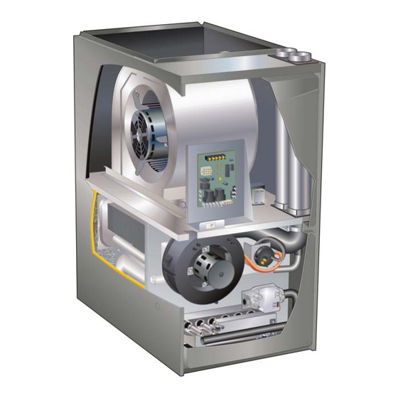
BLOWER DATA ML193DF045XP36B PERFORMANCE (Less Filter) ML193DF090XP48C PERFORMANCE (Less Filter) Air Volume / Watts at Various Blower Speeds Air Volume / Watts at Various Blower Speeds External External Static Medium- Medium- Static Medium- Medium- High High Pressure High Pressure High in. - Page 5 PARTS ARRANGEMENT CONTROL BOX (Includes integrated control, transformer and door switch) BAG ASSEMBLY BLOWER MOTOR (hidden) BLOWER ACCESS PANEL COMBUSTION AIR INDUCER BLOWER DECK PRIMARY LIMIT BURNER ACCESS COLD END HEADER BOX PANEL HEAT EXCHANGER GAS VALVE BURNER BOX ASSEMBLY (includes sensor, rollout switches and ignitor) FIGURE 1 Page 5...
-
Page 6: I-Unit Components
I-UNIT COMPONENTS WARNING ML193DF unit components are shown in figure 1. The combustion air inducer, gas valve and burners can be ac Shock hazard. cessed by removing the burner access panel. The blower Disconnect power before servicing. Control is not and control box can be accessed by removing the blower field repairable. - Page 7 tial in the prove switch is great enough, the prove switch Fan Control closes and a 15-second pre-purge begins. If the prove The fan on time of 30 seconds is not adjustable. The fan off delay (amount of time that the blower operates after the switch is not proven within 2-1/2 minutes, the integrated heat demand has been satisfied) may be adjusted by control goes into Watchguard-Pressure Switch mode for a...
- Page 8 The integrated control is equipped with two LED lights for troubleshooting. The diagnostic codes are listed below in table 3. TABLE 3 DIAGNOSTIC CODES Make sure to Identify LED'S Correctly. LED #1 (Red) LED #2 (Green) DESCRIPTION Power on - Normal operation. SIMULTANEOUS SIMULTANEOUS Also signaled during cooling and continuous fan.
- Page 9 4. Integrated Ignition Control 103085 (A92) TABLE 5 12-Pin Terminal Designations PIN # FUNCTION WARNING High Limit Output Sensor Shock hazard. 24V Line Disconnect power before servicing. Control is not Not Used field repairable. If control is inoperable, simply re place entire control.
- Page 10 INTEGRATED CONTROL (Automatic Hot Surface Ignition System) TERMINAL DESIGNATIONS Humidifier (120VAC) Input (120VAC) LINE Transformer (120VAC) XFMR Indoor Air Qality Accessory Air Cleaner (120VAC) Blower - Cooling Speed (120VAC) COOL Blower - Heating Speed (120VAC) HEAT Dead terminals to park alternate spd taps PARK Continuous blower CONT...
- Page 11 Fan Time Control Twinning 2 ML193DF Furnaces Heating Fan On Time Integrated control 103085 is equipped with a provision to ”twin” (interconnect) two(2) adjacent furnaces with a com The fan on time of 30 seconds is not adjustable. mon plenum such that they operate as one (1) large unit. Heating Fan Off Time When twinned, the circulating blower speeds are synchro...
- Page 12 FIELD WIRING FOR TWINNING THE ML193DF TWIN TWIN SINGLE STAGE THERMOSTAT TWO-STAGE THERMOSTAT Call For Cool Call For Cool TWIN 1 TWIN 1 Call For Fan Call For Fan Call For 1st Call For Heat Stage Heat Call For 2nd StageHeat TWIN TWIN...
- Page 13 B-Heating Components NOTE - The ML193DF furnace contains electronic components that are polarity sensitive. Make sure that Combustion air inducer (B6), primary limit control (S10), the furnace is wired correctly and is properly grounded. SureLight ignitor, burners, flame rollout switch (S47), gas valve (GV1), combustion air prove switch (S18), and clam...
- Page 14 IGNITOR CHECKS TABLE 7 Control Ohms Voltage + 10% 39 to 70 103085 24 to 47 100973 Test 1 Multi−Meter (set to ohms) Integrated Control Detail Test 1 Check ignitor circuit for correct resistance. Remove 4-pin plug from control. Check ohms reading across terminals 2 and 4. See table 7.
- Page 15 4. Primary Limit Control (Figure 12) burner input. See table 8 for orifice size. The burner is sup ported by the orifice and will easily slide off for service. A Primary limit (S10) used on ML193DF units is located in the flame retention ring in the end of each burner maintains heating vestibule panel.
- Page 16 8. Combustion Air Inducer (B6) Pressure Switch & Cold End Header Box All ML193DF units use a combustion air inducer to move air 24VAC BRACKET through the burners and heat exchanger during heating op TERMINALS eration. The blower uses a shaded pole 120VAC motor. The motor operates during all heating operation and is con...
- Page 17 Measuring Pressure Differential RED TUBING NEGATIVE BLACK TUBING POSITIVE Operate unit and observe manometer reading. Remove thermostat demand and allow unit to cycle off. Readings will change as heat exchanger warms. Install a tee in the negative (-) line (red tubing) and a tee in the a.
- Page 18 II-PLACEMENT AND INSTALLATION IMPORTANT Pipe & Fittings Specifications ML193DF exhaust and intake connections are made All pipe, fittings, primer and solvent cement must conform of PVC. Use PVC primer and solvent cement when with American National Standard Institute and the Ameri using PVC vent pipe.
-
Page 19: Outdoor Termination Usage
TABLE 12 OUTDOOR TERMINATION USAGE* STANDARD CONCENTRIC Flush Wall Kit Wall Ring Kit Mount 1-1/2 inch 2 inch 3 inch Vent 2 inch 3 inch 2 inch Pipe Input Size Field Dia. in. 51W11 71M80 69M29 Fabricated 44J40 (US) 22G44 (US) (US) (US) 60L46 (US) -
Page 20: Venting Practices
Venting Practices Joint Cementing Procedure All cementing of joints should be done according to the Piping Suspension Guidelines specifications outlined in ASTM D 2855. NOTE - A sheet metal screw may be used to secure the SCHEDULE 40 intake pipe to the connector, if desired. Use a drill or PVC - 5' all other pipe* - 3' self tapping screw to make a pilot hole. - Page 21 Contact Lennox' Application Department for assis Vent Piping Guidelines tance in sizing vent pipe in these applications. ® NOTE - Lennox has approved the use of DuraVent manu IMPORTANT factured vent pipe and terminations as an option to PVC.
- Page 22 NOTE - It is acceptable to use any pipe size which fits within the guidelines allowed in table 14. Piping Size Process NOTE - All horizontal runs of exhaust pipe must slope back toward unit. A minimum of 1/4” (6mm) drop for each 12” What is the (305mm) of horizontal run is mandatory for drainage.
- Page 23 TABLE 14 Maximum Allowable Intake or Exhaust Vent Length in Feet *Size intake and exhaust pipe length separately. Values in table are for Intake OR Exhaust, not combined total. Both Intake and Exhaust must be same pipe size. NOTE - Additional vent pipe and elbows used to terminate the vent pipe outside the structure must be included in the total vent length calculation. Standard Termination at Elevation 0 - 10,000 ft.
- Page 24 TYPICAL EXHAUST PIPE CONNECTIONS Pipe size determined in table 14. 2” 2” 2” 2” 2” 3” TRANSITION INTAKE EXHAUST DO NOT transition from smaller *2” to larger pipe size in horizontal TOP VIEW runs of exhaust pipe. * When transitioning up in pipe size, use the shortest length of 2” PVC pipe possible. NOTE −...
- Page 25 2 - Route piping to outside of structure. Continue with EQUIPMENT IN CONFINED SPACE installation following instructions given in general (Inlet Air from Ventilated Attic and Outlet Air to Outside) guide lines for piping terminations and intake and ex Ventilation Louvers haust piping terminations for direct vent sections.
- Page 26 Position termination according to location given in figure 27 closed areas that are not exposed to the outdoor ambient or 28. In addition, position termination so it is free from any temperature and are above 32 degrees F (0°C) are to be obstructions and 12”...
-
Page 27: Vent Termination Clearances
‡ Permitted only if veranda, porch, deck or balcony is fully open on a minimum of two sides beneath the floor. Lennox recommends avoiding this location if possible. FIGURE 27... - Page 28 ‡ Permitted only if veranda, porch, deck or balcony is fully open on a minimum of two sides beneath the floor. Lennox recommends avoiding this location if possible. FIGURE 28 Page 28...
- Page 29 Details of Intake and Exhaust Piping Terminations for NOTE - Care must be taken to avoid recirculation of exhaust back into intake pipe. Direct Vent Installations NOTE - In Direct Vent installations, combustion air is taken from outdoors and flue gases are discharged to outdoors. NOTE - Flue gas may be slightly acidic and may adversely Exiting Exhaust and Intake Vent affect some building materials.
- Page 30 34. OPTIONAL VENT TERMINATION FOR MULTIPLE UNIT INSTALLATION OF DIRECT VENT WALL TERMINATION KIT 1-1/2” (38mm) accelerator (30G28 or 81J20) provided on 71M80 & 44W92 kits for ML193DF045P36B- & FIGURE 34 070P36B FLASHING 2” EXTENSION FOR 2” PVC 12” (305mm) (Not Furnished) PIPE1”...
- Page 31 FIELD FABRICATED WALL TERMINATION NOTE − FIELD−PROVIDED REDUCER MAY BE 2” (51mm) 3” (76mm) REQUIRED TO ADAPT LARGER VENT PIPE SIZE Vent Pipe Vent Pipe TO TERMINATION A− Minimum clearance above grade or average 12” (305 mm) 12” (305 mm) snow accumulation B−...
- Page 32 2. On field supplied terminations for side wall exit, ex ML193DF DIRECT VENT APPLICATION haust piping may extend a maximum of 12 inches USING EXISTING CHIMNEY STRAIGHT-CUT OR ANGLE-CUT IN DIRECTION (305mm) for 2” PVC and 20 inches (508mm) for 3” OF ROOF SLOPE * (76mm) PVC beyond the outside wall.
- Page 33 Heat cable kit is avail of the unit. Install field-provided 1/2 NPT male fitting able from Lennox in various lengths; 6 ft. (1.8m) - kit into cold end header box. For furnaces with a 3/4”...
- Page 34 CONDENSATE TRAP LOCATION ML193DF with Evaporator Coil (shown with right side exit of condensation) Using a Separate Drain Field Provided Vent 1” min. 2” max. above Trap can be installed a maxi mum of 5ft. from furnace (*PVC condensate drain. only) Field Provided Vent 1”...
- Page 35 TRAP / DRAIN ASSEMBLY USING 1/2” PVC OR 3/4” PVC COLD END HEADER BOX WITH 3/4” DRAIN CONNECTION Optional Condensate Drain Connection Adapter 3/4 inch slip X 3/4 inch mpt (not furnished) 90° Street Elbow 3/4 inch PVC (not furnished) Adapter 3/4 inch slip X 3/4 inch mpt (not furnished) Condensate Drain...
- Page 36 TRAP / DRAIN ASSEMBLY USING 1/2” PVC OR 3/4” PVC Optional Condensate Drain Connection Adapter 1/2 inch slip X 1/2 inch mpt (Not Furnished) 90° Street Elbow 1/2 inch PVC (Not Furnished) Adapter 1/2 inch slip X 1/2 inch mpt (Not Furnished) Condensate Drain Connection In Unit 1 (25 mm) Min.
-
Page 37: Iii-Start-Up
III-START‐UP 2 - Set the thermostat to the lowest setting. 3 - Turn off all electrical power to the unit. A-Preliminary and Seasonal Checks 4 - This furnace is equipped with an ignition device which 1 - Inspect electrical wiring, both field and factory installed automatically lights the burners. -
Page 38: Iv-Heating System Service Checks
IV-HEATING SYSTEM SERVICE CHECKS available through Lennox under part number 31B2001. See Corp. 8411-L10, for further details. A-C.S.A. Certification All units are C.S.A. design certified without modifications. WARNING Refer to the ML193DF Operation and Installation Instruc tion Manual Information. Do not use matches, candles, flame or any other source of ignition to check for gas leaks. - Page 39 F- Proper Gas Flow (Approximate) G- Proper Combustion Gas Flow (Approximate) Furnace should operate at least 15 minutes with correct manifold pressure and gas flow rate before checking com TABLE 18 GAS METER CLOCKING CHART bustions. Take sample beyond the flue outlet and compare Seconds for One Revolution to table 20.
- Page 40 I-Flame Signal V-TYPICAL OPERATING CHARACTERISTICS A-Blower Operation and Adjustment A transducer (Part #78H5401 available from Lennox Re 1 - Blower operation is dependent on thermostat control pair Parts) is required to measure flame signal if meter system. used will not read a low micro amp signal. See figure 50.
-
Page 41: Vi-Maintenance
3 - Disconnect the 2 wires from the gas valve. specifications provided by the filter manufacturer 4 - Remove gas supply line connected to gas valve. Re against the data given in the appropriate Lennox move gas valve/manifold assembly. Product Specifications bulletin. Additional informa... - Page 42 6 - Disconnect wires from flame roll-out switches. 26 - Reinstall pressure switches and reconnect pressure switch wiring. 7 - Loosen clamps at vent elbow. Disconnect condensate 27 - Carefully connect combustion air pressure switch hos drain tubing from flue collar. and remove the vent el ing from pressure switches to proper stubs on cold end bow.
- Page 43 VII-WIRING DIAGRAM AND SEQUENCE OF OPERATION ML193DF With Integrated Control 100973 1 - When there is a call for heat, W1 of the thermostat en 5 - Gas valve opens for a 4-second trial for ignition ergizes W of the furnace control with 24VAC. 6 - Flame is sensed, gas valve remains open for the heat 2 - S10 primary limit switch and S47 rollout switch are call.
-
Page 44: Heating Sequence Of Operation
Sequence of Operation Flow Chart - Integrated Control 100973 HEATING SEQUENCE OF OPERATION ABNORMAL HEATING MODE NORMAL HEATING MODE POWER ON GAS VALVE OFF. COMBUSTION AIR INDUCER OFF. INDOOR BLOWER DELAY OFF. CONTROL SELF-CHECK OKAY? LED #1 ON LED #2 ON (RESET CONTROL BY TURNING MAIN POWER OFF.) POLARITY REVERSED. - Page 45 HEATING SEQUENCE CONTINUED NORMAL HEATING MODE ABNORMAL HEATING MODE 15‐SECOND COMBUSTION AIR INDUCER PREPURGE INITIATED BY CLOSED PRESSURE SWITCH. LEDS SIGNAL ALTERNATING FAST FLASH UNTIL IS VOLTAGE ABOVE 90 VOLTS? IGNITOR WARM‐UP -- 20 SECONDS. VOLTAGE IS ABOVE 95 VOLTS, THEN RESTARTS HEATING 4‐SECOND TRIAL FOR IGNITION.
- Page 46 COOLING SEQUENCE OF OPERATION NORMAL COOLING MODE ABNORMAL COOLING MODE POWER ON IGNITION CONTROL MAIN POWER ON. GAS VALVE OFF. COMBUSTION AIR INDUCER OFF. INDOOR BLOWER OFF WITH NORMAL DELAY. CONTROL SELF DIAGNOSTIC CHECK. SIGNAL CIRCUIT CONTROL FAILURE AT LED. IS CONTROL OPERATING NORMALLY? INTERRUPT MAIN POWER TO RESET CONTROL.
- Page 47 CONTINUOUS HEAT SPEED FAN SEQUENCE OF OPERATION LED: SLOW FLASH RATE REMAINS UNCHANGED THROUGHOUT SEQUENCE. MANUAL FAN SELECTION MADE AT THERMOSTAT. CONTROL (G) ENERGIZES SYSTEM FAN AT HEAT SPEED. EAC TERMINAL IS ENERGIZED. HUM TERM. ENERGIZES THERMOSTAT CALLS FOR HEAT (W). WITH COMB.
- Page 48 ML193DF With Integrated Control 103085 1 - When there is a call for heat, W1 of the thermostat en 5 - Gas valve opens for a 4-second trial for ignition ergizes W of the furnace control with 24VAC. 6 - Flame is sensed, gas valve remains open for the heat 2 - S10 primary limit switch and S47 rollout switch are call.
- Page 49 Sequence of Operation Flow Chart - Integrated Control 103085 HEATING SEQUENCE OF OPERATION ABNORMAL HEATING MODE NORMAL HEATING MODE POWER ON GAS VALVE OFF. COMBUSTION AIR INDUCER OFF. INDOOR BLOWER DELAY OFF. CONTROL SELF-CHECK OKAY? LED: OFF POLARITY REVERSED. IS POLARITY CORRECT? LED: 9 FLASHES IMPROPER GROUND.
- Page 50 HEATING SEQUENCE CONTINUED NORMAL HEATING MODE ABNORMAL HEATING MODE 15‐SECOND COMBUSTION AIR INDUCER PREPURGE INITIATED BY CLOSED PRESSURE SWITCH. LED: ON STEADY UNTIL VOLTAGE IS IS VOLTAGE ABOVE 90 VOLTS? IGNITOR WARM‐UP -- 20 SECONDS. ABOVE 95 VOLTS, THEN RESTARTS HEATING SEQUENCE.
- Page 51 COOLING SEQUENCE OF OPERATION NORMAL COOLING MODE ABNORMAL COOLING MODE POWER ON IGNITION CONTROL MAIN POWER ON. LED: ON STEADY GAS VALVE OFF. COMBUSTION AIR INDUCER OFF. INDOOR BLOWER OFF WITH NORMAL DELAY. CONTROL SELF DIAGNOSTIC CHECK. LED: OFF IS CONTROL OPERATING NORMALLY? INTERRUPT MAIN POWER TO RESET CONTROL.
Need help?
Do you have a question about the ML193DF045P36B and is the answer not in the manual?
Questions and answers