Lennox ML196DFE Series Unit Information
Hide thumbs
Also See for ML196DFE Series:
- Installation instructions manual (50 pages) ,
- Manual (52 pages) ,
- Installation instructions manual (11 pages)
Table of Contents
Advertisement
S e r v i c e L i t e r a t u r e
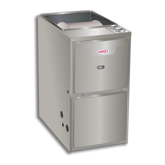
ML196DFE series units are high-efficiency gas furnaces
manufactured with Lennox DuralokPlus aluminized steel
clamshell-type heat exchangers, with a stainless steel
condensing coil. ML196DFE units are available in heating
input capacities of 44,000 to 110,000 Btuh and cooling ap-
plications from 2 through 5 tons. Refer to Product Specifi-
cations for proper sizing.
Units are factory equipped for use with natural gas. A kit
is available for conversion to LP/Propane operation. All
ML196DFE units are equipped with a hot surface ignition
system. The gas valve is redundant to assure safety shut-
off as required by C.S.A.
The heat exchanger, burners and manifold assembly can
be removed for inspection and service. The maintenance
section gives a detailed description on how this is done.
All specifications are subject to change. Procedures out-
lined in this manual are presented as a recommendation
only and do not supersede or replace local or state codes.
WARNING
Electric shock hazard. Can cause injury
or death. Before attempting to perform
any service or maintenance, turn the
electrical power to unit OFF at disconnect
switch(es). Unit may have multiple power
supplies.
Specifications . . . . . . . . . . . . . . . . . . . . . . . . . . . . . . . . . 2
Optional Accessories . . . . . . . . . . . . . . . . . . . . . . . . . . 3
Blower Performance Data . . . . . . . . . . . . . . . . . . . . . . 4
I-Unit Components . . . . . . . . . . . . . . . . . . . . . . . . . . . . 5
II Placement and Installation . . . . . . . . . . . . . . . . . . . . 19
III-Start-Up . . . . . . . . . . . . . . . . . . . . . . . . . . . . . . . . . . . 40
IV-Heating System Service Checks . . . . . . . . . . . . . . 41
V-Typical Operating Conditions . . . . . . . . . . . . . . . . . 45
VI-Maintenance . . . . . . . . . . . . . . . . . . . . . . . . . . . . . . . 46
VIII-Troubleshooting . . . . . . . . . . . . . . . . . . . . . . . . . . . 50
UNIT INFORMATION
UNIT INFORMATION
Corp 1910-L7
Revised 04/2022
ML196DFE SERIES UNITS
. . . . . . . . . . . 49
Page 1
WARNING
Improper
installation,
service or maintenance can cause property damage,
personal injury or loss of life. Installation and service
must be performed by a licensed professional HVAC
installer (or equivalent), service agency or the gas
supplier.
CAUTION
As with any mechanical equipment, contact with
sharp sheet metal edges can result in personal
injury. Take care while handling this equipment and
wear gloves and protective clothing.
ML196DFE
adjustment,
alteration,
©2016 Lennox Industries, Inc.
Advertisement
Table of Contents

Related Manuals for Lennox ML196DFE Series


Summary of Contents for Lennox ML196DFE Series
-
Page 1: Table Of Contents
S e r v i c e L i t e r a t u r e Revised 04/2022 ML196DFE SERIES UNITS ML196DFE series units are high-efficiency gas furnaces manufactured with Lennox DuralokPlus aluminized steel clamshell-type heat exchangers, with a stainless steel condensing coil. -
Page 2: Specifications
S PECIF IC ATIONS Model No. ML196DF045XE36B ML196DF070XE48B ML196DF090XE48C ML196DF110XE60C Heating AFUE Performance Input - Btuh 44,000 66,000 88,000 110,000 Output - Btuh 42,000 64,000 85,000 106,000 Temperature rise range - °F 30 - 60 35 - 65 50 - 80 40 - 70 Gas Manifold Pressure (in. -
Page 3: Optional Accessories
OPT IONAL AC C ESSORIES “B” Width Models “C” Width Models CABINET ACCESSORIES Downflow Combustible Flooring Base 11M60 11M61 CONDENSATE DRAIN KITS Condensate Drain Heat Cable 6 ft. 26K68 26K68 24 ft. 26K69 26K69 Crawl Space Vent Drain Kit 51W18 51W18 15Z70 15Z70... -
Page 4: Blower Performance Data
BLOWER DATA ML196DF045XE36B PERFORMANCE (Less Filter) Air Volume / Watts at Various Blower Speeds External High Medium-High Medium Medium-Low Static (Black) (Brown) (Blue) (Yellow) (Red) Pressure in. w.g. Watts Watts Watts Watts Watts 0.00 1455 1275 1175 0.10 1425 1250 1145 0.20 1395... - Page 5 PARTS ARRANGEMENT CONTROL BOX (Includes integrated control, transformer, circuit breaker and door switch) BLOWER MOTOR (hidden) BAG ASSEMBLY (shipping location) BLOWER ACCESS PANEL COMBUSTION AIR INDUCER BLOWER DECK DuralokPlus HEAT EXCHANGER ASSEMBLY BURNER ACCESS PANEL COLD END HEADER BOX COMBUSTION AIR INDUCER PRESSURE SWITCH PRIMARY LIMIT BURNER BOX ASSEMBLY...
-
Page 6: I-Unit Components
I-UNIT COMPONENTS If the current exceeds this limit the breaker will trip and all unit operation will shutdown. The breaker can be manually ELECTROSTATIC DISCHARGE (ESD) reset by pressing the button on the face. Precautions and Procedures 4. Integrated Ignition Control (A92) CAUTION 103217-03 &... - Page 7 TABLE 3 1/4” Quick Connect Terminals 120HUM Humidifier 120VAC LINE 120VAC XFMR Transformer 120VAC CIRC Indoor blower 120VAC Indoor air quality accessory 120VAC NEUTRALS Common 120VAC HUM24 Humidifier 24VAC 3/16” Quick Connect Terminals COOL Cooling tap 24VAC HEAT Heating tap 24VAC Continuous blower 24 VAC PARK Park terminal for speed taps...
- Page 8 After a total of five trials for ignition (including the initial trial), the integrated control goes into Watchguard-Flame IGNITION CONTROL 103217-03 Failure mode. After a 60-minute reset period, the integrat- ed control will begin the ignition sequence again. Fan Time Control - Ignition Control 103217-03 Heating Fan On Time The fan on time of 30 seconds is not adjustable.
- Page 9 TABLE 5 Ignition Control 107163-01 RED LED Flash Code Diagnostic Codes / Status of Furnace No Power to Control or Board Fault Detected Board Fault Detected Fast Heartbeat Call for Heat / Burner Operation Slow Heartbeat Normal Operation – Idle, Continuous Fan, or Cool 1 Flash Reverse Line Voltage Polarity or Phasing of 120V power 2 Flashes...
- Page 10 Burner Box Assembly Burner Assembly Rollout Switch(s) Flame Sensor Ignitor Gas Valve Burner Box Front FIGURE 6 B-Heating Components 2. Heat Exchanger (FIGURE 7) Combustion air inducer (B6), primary limit control (S10), ML196DFE units use an aluminized steel primary and SureLight ignitor, burners, flame rollout switch (S47), gas stainless steel secondary heat exchanger assembly.
- Page 11 5. Flame Sensor (FIGURE 6) Primary Limit Location and Heat Exchanger A flame sensor is located on the left side of the burner support. The sensor is mounted on the bottom burner box plate and the tip protrudes into the flame envelope of the leftmost burner.
- Page 12 Measuring Flame Signal Flame Signal In Microamps Normal Drop Out 0.5 - 1.4 Flame Sensor Terminal Remove Sensor Wire from Intergrated Control and Intergrated Connect Alligator Clip (−) Control to Frame Sensor Lead Remove Sensor Wire from Intergrated Control and Connect Alligator Clip (+) to Terminal on Control Multi−Meter...
- Page 13 Test 1 Check ignitor circuit for correct resistance. Remove 4-pin plug from control. Check ohms reading across terminals 2 and 4. Reading should be between 39 and 70 ohms. If value is correct, this is the only test needed. If the reading on the meter is not correct, (0 or infinity) then a second test is needed.
- Page 14 Checks of pressure differential can aid in troubleshoot- ing. When measuring the pressure differential, readings ML196DFE series units are equipped with a differential should be taken at the pressure switch. See FIGURE 12 pressure switch located on the cold end header box. The and TABLE 8.
- Page 15 Measuring Pressure Differential Black Tubing (positive +) Red and Black Tubing or Red Tubing (negative -) To Cold End Header Box To Cold End Header Box Field Provided Tubing To Pressure Switch “+” High “-” 1 - Remove thermostat demand and allow unit to cycle off.
- Page 16 TABLE 8 Problem Corrective Action Check that the pressure switch is open without the com- Pressure switch stuck closed bustion air inducer operating. Replace if defective. Pressure switch does not close due to obstruction in vent Check for restricted vent. Remove all blockage. Check for pipe.
- Page 17 C- Blower Compartment BLOWER WHEEL REPLACEMENT IMPORTANT Center Blower Wheel in Blower Housing Each blower is statically and dynamically balanced as an assembly before installation in the unit. ML196DFE units are equipped with a constant torque ECM motor. It has a DC motor coupled to an electronic control module both contained in the same motor housing.
- Page 18 Multi−Meter (set to VAC) Multi−Meter (set to VAC) Test 1 Test 3 (if necesssary) Turn on power to unit. Check for 120 volts across terminals Check for 120 volts across terminals “CIRC” and “Neutrals” “L” and “N” on input plug P48. If voltage is present continue on the integrated control.
- Page 19 Replacing the Motor Module Motor Test 1 - Disconnect electrical power to unit. 8 - Remove unit access panel. 9 - Unplug the two harnesses from the motor control module. See FIGURE 17. 10 - Remove the two hex head bolts securing the motor control module to the motor.
-
Page 20: Placement And Installation
II-PLACEMENT AND INSTALLATION IMPORTANT Pipe & Fittings Specifications Exhaust and intake connections are made of PVC. All pipe, fittings, primer and solvent cement must conform Use PVC primer and solvent cement when using with American National Standard Institute and the Ameri- PVC vent pipe. - Page 21 TABLE 11 OUTDOOR TERMINATION USAGE* STANDARD CONCENTRIC Flush Mount Wall Kit 1-1/2 inch 2 inch 3 inch Vent Pipe Input Size 2 inch 3 inch Field Dia. in. 71M80 (US) 69M29 (US) 60L46 (US) Fabricated 51W11 (US) 22G44 (US) 44W92 44W92 444W93 44J40 (US)
- Page 22 Removal of the Furnace from Common Vent Venting Practices In the event that an existing furnace is removed from a venting system commonly run with separate gas applianc- Piping Suspension Guidelines es, the venting system is likely to be too large to properly vent the remaining attached appliances.
- Page 23 NOTE - Exhaust piping should be checked carefully to make NOTE - Lennox offers a glueless vent adapter kit 17H92 as an sure there are no sags or low spots. option for exhaust exiting at the furnace top cap coupling.
- Page 24 TABLE 13 NOTE - Size intake and exhaust pipe length separately. Values in table are for Intake OR Exhaust, not combined total. Both Intake and Exhaust must be same pipe size. NOTE - Additional vent pipe and elbows used to terminate the vent pipe outside the structure must be included in the total vent length calcu- lation.
- Page 25 TABLE 13 continued NOTE - Size intake and exhaust pipe length separately. Values in table are for Intake OR Exhaust, not combined total. Both Intake and Exhaust must be same pipe size. NOTE - Additional vent pipe and elbows used to terminate the vent pipe outside the structure must be included in the total vent length calcu- lation.
- Page 26 TABLE 14 Maximum Allowable Exhaust Vent Lengths With Furnace Installed in a Closet or Basement Using Ventilated Attic or Crawl Space For Intake Air in Feet NOTE - Additional vent pipe and elbows used to terminate the vent pipe outside the structure must be included in the total vent length calculation.
- Page 27 TYPICAL EXHAUST PIPE CONNECTIONS 045/070 Only 2” 1−1/2” 2” 2” 2” 2” TRANSITION 2” Exhaust Exhaust 3” DO NOT transition from larger to smaller pipe in horizontal runs of exhaust pipe. TRANSITION INTAKE EXHAUST DO NOT transition from smaller *2” to larger pipe size in horizontal TOP VIEW runs of exhaust pipe.
- Page 28 Intake Piping TYPICAL AIR INTAKE PIPE CONNECTIONS The ML196DFE furnace may be installed in either direct NON−DIRECT VENT APPLICATIONS vent or non-direct vent applications. In non-direct vent applications, when intake air will be drawn into the furnace INTAKE SCREEN from the surrounding space, the indoor air quality must be (Provided) considered.
- Page 29 In Direct Vent applications, combustion air is taken from EQUIPMENT IN CONFINED SPACE outdoors and the flue gases are discharged to the out- (Inlet Air from Ventilated Attic and Outlet Air to Outside) doors. The ML196DFE is then classified as a direct vent, Category IV gas furnace.
- Page 30 TABLE 15 Maximum Allowable Exhaust Vent Pipe Length (in ft.) Without Insulation In Unconditioned Space For Winter Design Temperatures Single - Stage High Efficiency Furnace Winter Design Unit Input Size Vent Pipe Diameter Temperatures °F (°C) 1-1/2 in 32 to 21 2 in (0 to -6) 2-1/2 in...
- Page 31 ‡ Permitted only if veranda, porch, deck or balcony is fully open on a minimum of two sides beneath the floor. Lennox recommends avoiding this location if possible. FIGURE 30...
- Page 32 ‡ Permitted only if veranda, porch, deck or balcony is fully open on a minimum of two sides beneath the floor. Lennox recommends avoiding this location if possible. FIGURE 31 Page 32...
- Page 33 Details of Intake and Exhaust Piping Terminations for 6 - On field supplied terminations, a minimum distance Direct Vent Installations between the end of the exhaust pipe and the end of the intake pipe without a termination elbow is 8” and NOTE - In Direct Vent installations, combustion air is taken a minimum distance of 6”...
- Page 34 7 - If intake and exhaust piping must be run up a side wall to position above snow accumulation or other obstructions, iping must be supported. At least 12” EXHAUST one bracket must be used within 6” from the top of (305mm) VENT 5-1/2”...
- Page 35 FIELD FABRICATED WALL TERMINATION NOTE − FIELD−PROVIDED REDUCER MAY BE 2” (51mm) 3” (76mm) REQUIRED TO ADAPT LARGER VENT PIPE SIZE Vent Pipe Vent Pipe TO TERMINATION A− Minimum clearance above grade or average 12” (305 mm) 12” (305 mm) snow accumulation B−...
- Page 36 KIT 15Z70 Crawl Space and Extended Horizontal Venting (CANADA) Lennox provides kit 51W18 (USA) and kit 15Z70 (Cana- FIGURE 43 da) to install 2” or 3” PVC exhaust piping through the floor joists and into the the crawl space. See FIGURE 43.
- Page 37 4 - Install drain trap using appropriate PVC fittings, glue and line. Heat cable kit is available from Lennox in various all joints. Glue the provided drain trap as shown in lengths;...
- Page 38 IMPORTANT Furnace with Evaporator Coil Using a Separate Drain When combining the furnace and evaporator coil drains together, the A/C condensate drain outlet must be vented to relieve pressure in order for the Field Provided Vent furnace pressure switch to operate properly. 1”...
- Page 39 TRAP / DRAIN ASSEMBLY USING 1/2” PVC OR 3/4” PVC Optional Condensate Drain Connection Adapter 3/4 inch slip X 3/4 inch mpt (not furnished) 90° Street Elbow 3/4 inch PVC (not furnished) Adapter 3/4 inch slip X 3/4 inch mpt (not furnished) Condensate Drain Connection In Unit 1 (25 mm) Min.
-
Page 40: Iii-Start-Up
III-START-UP 2 - Set the thermostat to the lowest setting. 3 - Turn off all electrical power to the unit. A-Preliminary and Seasonal Checks 4 - This furnace is equipped with an ignition device 1 - Inspect electrical wiring, both field and factory which automatically lights the burners. -
Page 41: Iv-Heating System Service Checks
IV-HEATING SYSTEM SERVICE CHECKS Use of a specialty Gas Leak Detector is strongly recom- mended. It is available through Lennox under part number A-C.S.A. Certification 31B2001. See Corp. 8411-L10, for further details. All units are C.S.A. design certified without modifications. - Page 42 Negative Barbed Fitting (remove for manifold adjustment) (−) 2” Long Square Tubing (remove for manifold adjustment) Manifold Pressure Outlet Gas Valve Regulator Vent Hose (to burner box) Barbed Fitting 10” Long Square Tubing Measuring Device FIGURE 53 TABLE 17 Manifold and Supply Line Pressure 0-10,000ft. Manifold Pressure in.
- Page 43 F- Proper Gas Flow (Approximate) TABLE 19 ML196 Unit % Nat % LP TABLE 18 -045 GAS METER CLOCKING CHART -070 Seconds For One Revolution 7.5 - 8.5 8.6 - 9.6 -090 ML196 Natuarl LP/Propane Unit -110 1 cu ft 2 cu ft 1 cu ft 2 cu ft...
- Page 44 I- Proper Ground and Voltage 2 - In addition, measure the AC voltage from Line Hot to Line Neutral (spade terminals) on the integrated WARNING control. See FIGURE 54. This voltage should be in the range of 97 to 132 Vac. Electric Shock Hazard.
-
Page 45: V-Typical Operating Conditions
V-TYPICAL OPERATING CHARACTERISTICS C-External Static Pressure 1 - Tap locations shown in FIGURE 56. A-Blower Operation and Adjustment1 2 - Punch a 1/4” diameter hole in supply and return air NOTE- The following is a generalized procedure and does plenums. Insert manometer hose flush with inside not apply to all thermostat controls. -
Page 46: Vi-Maintenance
Before using any filter with this system, check the FIGURE 57 specifications provided by the filter manufacturer against the data given in the appropriate Lennox Product Winterizing and Condensate Trap Care Specifications bulletin. Additional information is provided 1 - Turn off power to the furnace. - Page 47 Condensate Hose Screen (FIGURE 58) 12 - Disconnect the plug from the combustion air inducer. Remove two screws which secure combustion air Check the condensate hose screen for blockage and inducer to collector box. Remove combustion air clean if necessary. inducer assembly.
- Page 48 28 - Reinstall exhaust and air intake pipe seal plate. Cleaning the Burner Assembly (if needed) Reinstall exhaust and air intake pipes and tighten 1 - Turn off electrical and gas power supplies to furnace. clamps on pipe seal plate. Remove upper and lower furnace access panels.
-
Page 49: Vii-Wiring And Sequence Of Operation
VII-WIRING DIAGRAM AND SEQUENCE OF OPERATION 1 - Line voltage is applied to L1 and N. the T1 low voltage transformer is energized, and line voltage is applied to B3 indoor blower. 2 - S47 rollout switch(es) must be closed in order for 24V from transformer to be output on integrated control ”R” to power thermostat. 3 - When there is a call for heat, W1 of the thermostat energizes W of the furnace control with 24VAC. -
Page 50: Viii-Troubleshooting
VIII-Troubleshooting: Heating Sequence of Operation HEATING SEQUENCE OF OPERATION ABNORMAL HEATING MODE NORMAL HEATING MODE POWER ON GAS VALVE OFF. COMBUSTION AIR INDUCER OFF. INDOOR BLOWER DELAY OFF. CONTROL SELF-CHECK OKAY? LED SLOW FLASH (RESET CONTROL BY TURNING MAIN POWER OFF.) LED FLASHES CODE 1 - POLARITY REVERSED. - Page 51 Heating Sequence of Operation Continued HEATING SEQUENCE CONTINUED 15 SECOND COMBUSTION AIR INDUCER PREPURGE INITIATED BY CLOSED PRESSURE SWITCH. LED FLASHES CODE 13 - LOW LINE VOLTAGE. ONCE VOLTAGE IS ABOVE IS VOLTAGE ABOVE 70 VOLTS? IGNITOR WARM UP -- 20 SECONDS. 75 VOLTS, HEATING SEQUENCE RESTARTS.
- Page 52 Cooling Sequence of Operation COOLING SEQUENCE OF OPERATION POWER ON IGNITION CONTROL MAIN POWER ON. GAS VALVE OFF. COMBUSTION AIR INDUCER OFF. INDOOR BLOWER OFF WITH NORMAL DELAY. CONTROL SELF DIAGNOSTIC CHECK. SIGNAL CIRCUIT BOARD FAILURE AT LED. IS CONTROL OPERATING NORMALLY? INTERRUPT MAIN POWER TO RESET CONTROL.
- Page 53 Continuous Fan / Accessories Sequence of Operation CONTINUOUS FAN SEQUENCE OF OPERATION LED: SLOW FLASH RATE REMAINS UNCHANGED THROUGHOUT SEQUENCE. MANUAL FAN SELECTION MADE AT THERMOSTAT. CONTROL (G) ENERGIZES SYSTEM FAN AT FAN SPEED. EAC TERMINAL IS ENERGIZED. THERMOSTAT CALLS FOR HEAT (W). SYSTEM FAN CONTINUES FAN SPEED WITHOUT THERMOSTAT CALLS FOR COOLING.
Need help?
Do you have a question about the ML196DFE Series and is the answer not in the manual?
Questions and answers