
Related Manuals for Hinkley CHET 36


Summary of Contents for Hinkley CHET 36
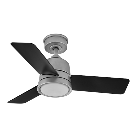
- Page 1 36” CHET INDOOR / OUTDOOR LED FAN CONTROL AC MOTOR CEILING FAN INSTRUCTION MANUAL hinkley.com CUL Model No. 36-TREM...
- Page 2 SO WE’RE HERE IF YOU HAVE A QUESTION, NEED SOME HELP OR WANT TO CHAT ABOUT OUR PRODUCTS, SEND SUGGESTIONS OUR WAY TOO - WE’RE ALWAYS LOOKING TO MAKE YOUR EXPERIENCE WITH HINKLEY A POSITIVE ONE. > SERVICE@HINKLEY.COM > 800.HINKLEY >...
-
Page 3: Table Of Contents
TROUBLESHOOTING HANGING THE FAN ENERGY GUIDE ELECTRICAL CONNECTIONS SPECIFICATIONS FINISHING THE INSTALLATION HINKLEY APP/WIFI INSTALLING THE BLADES SMART BY BOND WARNING: Read and follow these instructions carefully and be mindful of all warnings shown throughout. ©2022 Hinkley Lighting, Inc. hinkley.com... - Page 4 If you think batteries might have been swallowed or placed inside any part of the body, seek immediate medical attention. WARNING: To reduce the risk of fire or electric shock, this fan should only be used with fan speed control part no. MR161C manufactured by Chungear Industrial Co., Ltd. Note: Suitable for use in wet locations. hinkley.com...
-
Page 5: Important Safety Precautions
These factors must be supplied by the person(s) installing, caring for and operating the unit. TOOLS & MATERIALS REQUIRED • PHILLIPS SCREWDRIVER • FLAT SCREWDRIVER • WRENCH OR PLIERS • WIRE CUTTERS • STEP LADDER • WIRING SUPPLIES AS REQUIRED BY ELECTRICAL CODE ©2022 Hinkley Lighting, Inc. hinkley.com... -
Page 6: Unpacking Your Fan
16W LED Assembly E905236LED Shade Assembly GL905236FR Receiver incl. Wire Nuts CN905236 CR2032 HINKLEY Wall Control w/2032 Battery, Cradle A, Wall Pate, Face Plate, Mounting 980014FWH Screws, Cradle B (for flat wall use only) Hardware Bag Hanging bracket hardware, Safety... -
Page 7: Preparation
Loosen screw with key slot and remove canopy. Attach hanging bracket to outlet box using screws provided with Hanger the outlet box. Bracket Flat Washer Spring Washer Outlet Box Screw Figure 2 ©2022 Hinkley Lighting, Inc. hinkley.com... -
Page 8: Hanging The Fan
Securely tighten set screw against downrod using a large flat-head screwdriver to ensure a tight fit against downrod. Tighten nuts against mounting collar. Figure 1 Hook-up (3) Wires Downrod Security Screws Moumting Collar Cotter pin Downrod pin Top of Fan Body Figure 2 hinkley.com... - Page 9 Feed the end of the cable into the clamp and pull as much cable through as possible. Safety Cable Loop Firmly tighten screw in the clamp. Cut off excess cable. Wood Screw And Washer Safety Cable Figure 5 ©2022 Hinkley Lighting, Inc. hinkley.com...
-
Page 10: Electrical Connections
Connect the BLACK building supply wire to the BLACK receiver wire. Connect the WHITE receiver neutral wire to the WHITE building neutral wire. Receiver Connect the COPPER building ground wire to the 2 GREEN BLUE WHITE ground wires from the fan. BLACK BLACK WHITE BLUE Figure 2 hinkley.com... -
Page 11: Finishing The Installation
Trim Ring WARNING: Make sure the hook on the hanging bracket properly sits in the groove in the hanger ball before attaching the canopy to the bracket by turning the housing until it drops into place. ©2022 Hinkley Lighting, Inc. hinkley.com... -
Page 12: Installing The Blades
Turn the light kit pan clockwise, tightened the screws. Re-install the screw that was removed in step 1 and tighten firmly. Mounting Hub (bottom of motor) LK Pan Screws hinkley.com... -
Page 13: Installing The Led Assembly And Glass Shade
Place the glass shade into the light kit pan, aligning the three flat areas on the top of the glass shade with the three raised G la ss sha d e dimples in the light kit pan. Turn the glass shade clockwise until it stops. ©2022 Hinkley Lighting, Inc. hinkley.com... -
Page 14: Installing The Wall Control
Remote transmitter will be held in place with built in magnets. Remote transmitter will be held in place with built in magnets. Outlet box Wall plate Cradle B Wall plate Plastic Face plate anchor Transmitter Cradle A Face plate Transmitter Wall Figure 1 Figure 2 HIRO Control System hinkley.com... - Page 15 Attach cradle A to the wall switch box using supplied hardware. Attach the multi-gang face plate (not included) to the switch set in the wall outlet box. Cradle A Hinkley switch will fit in any standard decora face plate. NOTE: Remote transmitter will be held in place with built in magnets.
-
Page 16: Operation
NOTE: A single fan can be controlled with as many as 3 wall controls in one room. Every control will need to repeat the pairing process based on instructions above and all controls must be within 30 feet of the fan. hinkley.com... - Page 17 An UPWARD airflow moves warmer air off the ceiling area as shown in Figure 4. This allows you to set your heating unit on a cooler setting without affecting your comfort. Summer Mode Winter Mode (Counter Clockwise Direction) (Clockwise Direction) Figure 3 Figure 4 ©2022 Hinkley Lighting, Inc. hinkley.com...
-
Page 18: Care And Cleaning
WARNING: To reduce the risk of personal injury, do not bend the blade arm while installing, balancing the blades, or cleaning the fan. Do not insert foreign objects between rotating fan blades. Remote Control Do not connect the fan with a wall mounted variable speed control(s). Malfunction. 2. Make sure the dip switches are set correctly. hinkley.com... -
Page 19: Energy Guide
ENERGY GUIDE SPECIFICATIONS AVERAGE PERFORMANCE AND ENERGY INFORMATION PERFORMANCE STANDARD SPECIFICATIONS HIGH SPEED LOW SPEED Airflow (CFM) 3132 1907 Energy Use (Watts) 35.43 12.93 Airflow Efficiciency (CFM/W) Energy Costs (Yearly) Amps 0.32 RPMs ©2022 Hinkley Lighting, Inc. hinkley.com... - Page 20 In addition to the included wall control, you can control your Hinkley fan through the Hinkley app. • To use the Hinkley app, download it for free from the App Store or Google Play. • Open the Hinkley app where you will be prompted to create an account.
-
Page 21: Smart By Bond
Wait 10 seconds. f) Hold down the Power button on the transmitter you wish to pair. In addition to the included wall control, you can control your Hinkley The fan light should flash three times and the motor spin up for fan through the Bond app. - Page 22 HINKLEY IS PROUD TO PROVIDE YOU WITH CEILING FAN PRODUCTS THAT ENHANCE YOUR SPACE WITH COMFORT, PURPOSE AND STYLE. AS A FAMILY COMPANY, WE ARE COMMITTED TO DESIGN, PERFORMANCE AND QUALITY, AND WHAT’S IMPORTANT TO YOU IS PARAMOUNT TO US.
- Page 23 GLOBAL HEADQUARTERS 33000 Pin Oak Parkway I Avon Lake, Ohio 44012 T (440) 653 5500 F (440) 653 5555 hinkley.com...
- Page 24 CHET DE 91.4 CM VENTILADOR CON LUZ LED PARA INTERIORES / EXTERIORES CONTROL AC MOTOR MANUAL DE INSTRUCCIONES PARA VENTILADORES DE TECHO hinkley.com...
- Page 25 ASÍ QUE ESTAMOS AQUÍ SI TIENES ALGUNA PREGUNTA, NECESITAS AYUDA O DESEAS HABLAR SOBRE NUESTROS PRODUCTOS, O ENVIARNOS SUGERENCIAS TAMBIÉN - SIEMPRE ESTAMOS BUSCANDO HACER QUE TU EXPERIENCIA CON HINKLEY SEA POSITIVA. > SERVICE@HINKLEY.COM > 800.HINKLEY > A VER ESE ESTILO HINKLEY @HINKLEY...
- Page 26 GUÍA DE CONSUMO DE ENERGÍA CONEXIONES ELÉCTRICAS ESPECIFICACIONES CÓMO CONCLUIR LA INSTALACIÓN APLICACIÓN HINKLEY/WIFI CÓMO INSTALAR LAS ASPAS ADVERTENCIA: Lee y sigue estas instrucciones atentamente y ten en cuenta todas las advertencias que se muestran. ©2022 Hinkley Lighting, Inc. hinkley.com...
-
Page 27: Instrucciones Generales De Instalación Yfuncionamiento
En caso de sospecha de ingestión o penetración de las baterías en cualquier parte del cuerpo hay que buscar de inmediato atención médica. ADVERTENCIA: Para reducir el riesgo de incendio o descarga eléctrica, este ventilador solo debe usar la pieza núm. MR161C de control de velocidad de ventilador fabricada por Chungear Industrial Co., Ltd. Nota: Puede usarse en lugares húmedos. hinkley.com... -
Page 28: Instrucciones Importantes De Seguridad
HERRAMIENTAS Y MATERIALES NECESARIOS • DESTORNILLADOR PHILLIPS • DESTORNILLADOR PLANO • LLAVE O ALICATES • CORTACABLES • ESCALERA DE TIJERA • SUMINISTROS DE CABLEADO SEGÚN LO REQUIERE EL CÓDIGO ELÉCTRICO ©2022 Hinkley Lighting, Inc. hinkley.com... -
Page 29: Cómo Desempacar El Ventilador
Conjunto de pantalla GL905236FR Tuercas para cables incluidas con el CN905236 receptor CR2032 HINKLEY Control de pared con batería 2032, soporte A, placa de pared, placa 980014FWH frontal, tornillos de montaje, soporte B (solo para uso en paredes planas) Bolsa de herrajes... -
Page 30: Preparación
Afloja el tornillo con ranura para llave y retira la cubierta. Fija el soporte para colgar a la caja eléctrica con los tornillos Arandela plana provistos con la caja eléctrica. Arandela de resorte Tornillo de la caja eléctrica Figura 2 ©2022 Hinkley Lighting, Inc. hinkley.com... -
Page 31: Cómo Colgar El Ventilador
Conexión (3) Cables ajuste perfecto contra el tubo. Aprieta las tuercas contra el collarín de montaje. Tubo bajante Tornillos de Seguridad Collar de montaje Pasador Pasador de varilla de chaveta Parte superior del cuerpo del ventilador Figura 2 hinkley.com... - Page 32 Tornillo para madera posible. Apriete firmemente el tornillo en la abrazadera. Corte el y arandela exceso de cable. Cable de seguridad Figura 5 ©2022 Hinkley Lighting, Inc. hinkley.com...
-
Page 33: Conexiones Eléctricas
NEGRO Conecta el cable neutro del receptor BLANCO al cable neutro del inmueble BLANCO. Conecta el cable de COBRE de conexión a tierra del inmueble a los 2 cables de tierra VERDES del ventilador. NEGRO BLANCO AZUL Figura 2 hinkley.com... -
Page 34: Cómo Concluir La Instalación
Asegúrate de que el gancho del soporte para colgar se asiente correctamente en la ranura de la esfera de suspensión antes de sujetar la cubierta al soporte girando la carcasa hasta que encaje en su lugar. ©2022 Hinkley Lighting, Inc. hinkley.com... -
Page 35: Cómo Instalar Las Aspas
Gira la carcasa del kit de luces hacia la derecha y aprieta los tornillos. Cubo de montaje Vuelve a instalar el tornillo que retiraste en el paso 1 y apriétalo (parte inferior del motor) firmemente. Bandeja LK Tornillos hinkley.com... -
Page 36: Instalación Del Conjunto Del Led Y La Pantalla De
Coloca la pantalla de vidrio dentro de la carcasa kit de luces alineando las tres áreas planas en la parte superior de la pantalla con las tres muescas salientes en la carcasa. Gira la pantalla de vidrio de izquierda a derecha hasta que se detenga. ©2022 Hinkley Lighting, Inc. hinkley.com... -
Page 37: Cómo Instalar El Control De Pared
El transmisor remoto se mantendrá en su lugar con los imanes incorporados. incorporados. Caja eléctrica Placa de pared Cuna B Placa de pared Anclaje Placa frontal plástico Transmisor Cuna A Placa frontal Transmisor Pared Figura 1 Figura 2 Sistema de control HIRO hinkley.com... - Page 38 Fije la cuna A a la caja de interruptores de pared utilizando los accesorios suministrados. Fije la placa frontal multidispositivo (no incluida) al juego de interruptores en la caja de salida de la pared. El interruptor Cradle A Hinkley encajará en cualquier placa frontal decora estándar. Interruptor Figura 3 NOTA: El transmisor remoto se mantendrá...
-
Page 39: Funcionamiento
NOTA: Un solo ventilador se puede controlar con hasta 3 controles de pared en una habitación. Cada control deberá repetir el proceso de emparejamiento según las instrucciones anteriores y todos los controles deben estar a menos de 9.1 m (30 pies) del ventilador. hinkley.com... - Page 40 Modo Verano Modo Invierno (En sentido contrario a las agujas del reloj) (En sentido de las agujas del reloj) Figura 3 Figura 4 ©2022 Hinkley Lighting, Inc. hinkley.com...
-
Page 41: Cuidado Y Limpieza
No insertes objetos extraños entre las aspas giratorias del ventilador. Control remoto No conectes el ventilador con un control o controles de velocidad variable de montaje en pared. Mal funcionamiento. 2. Asegúrate de que los interruptores en línea estén configurados correctamente. hinkley.com... -
Page 42: Guía De Consumo De Energía
• Basado en 12 centavos por kWh y 6.4 horas de uso por día Amperios 0.32 por vatio • Su costo depende de las tarifas y el uso • Energía usada: 20 W RPMs Todas las estimaciones se basan en el uso típico, excluyendo las luces ftc.gov/energy ©2022 Hinkley Lighting, Inc. hinkley.com... - Page 43 Hinkley mediante la aplicación Hinkley. • Para usar la aplicación Hinkley, descárguela gratis de App Store o Google Play. • Abra la aplicación Hinkley donde se le pedirá que cree una cuenta. • Ingrese toda la información necesaria para crear una cuenta.
- Page 44 CON COMODIDAD, PROPÓSITO Y ESTILO. COMO EMPRESA FAMILIAR, ESTAMOS COMPROMETIDOS CON EL DISEÑO, EL RENDIMIENTO Y LA CALIDAD, Y LO QUE ES IMPORTANTE PARA TI ES FUNDAMENTAL PARA NOSOTROS. PARA UNA VARIEDAD COMPLETA DE NUESTROS PRODUCTOS Y LIBROS DE CONSULTA, VISITA HINKLEY.COM.
- Page 45 GLOBAL HEADQUARTERS 33000 Pin Oak Parkway I Avon Lake, Ohio 44012 T (440) 653 5500 F (440) 653 5555 hinkley.com...
- Page 46 CHET DE 91 C M VENTILATEUR LED INTÉRIEUR / EXTÉRIEUR CONTROL AC MOTOR MODE D’EMPLOI POUR VENTILATEUR DE PLAFOND hinkley.com...
- Page 47 ALORS NOUS SOMMES LÀ SI VOUS AVEZ DES QUESTIONS, BESOIN D’ A IDE OU SI VOUS VOULEZ DISCUTER DE NOS PRODUITS. ENVOYEZ-NOUS AUSSI DES SUGGESTIONS, CAR NOUS CHERCHONS TOUJOURS À CE QUE VOTRE EXPÉRIENCE AVEC HINKLEY SOIT POSITIVE. > SERVICE@HINKLEY.COM >...
- Page 48 SUSPENSION DU VENTILATEUR GUIDE ÉCONERGÉTIQUE CONNEXIONS ÉLECTRIQUES CARACTÉRISTIQUES TERMINER L’INSTALLATION APPLICATION HINKLEY/WIFI INSTALLATION DES PALES AVERTISSEMENT : Veuillez lire et suivre et attentivement ces instructions. Tenez compte de toutes les mises en garde qui y figurent. © 2022 Hinkley Lighting, Inc. hinkley.com...
-
Page 49: Instructions D'installation Et D'utilisation
à un médecin. AVERTISSEMENT : Pour réduire les risques d’incendie ou d’électrocution, ce ventilateur ne devrait être utilisé qu’avec le dispositif de contrôle de la vitesse, pièce no MR161C, fabriqué par Chungear Industrial Co., Ltd. Remarque : Utilisation sécuritaire dans les endroits humides. hinkley.com... -
Page 50: Consignes De Sécurité Importantes
être intégrées à ce produit. Il incombe aux personnes qui installent, entretiennent et utilisent cet appareil d’agir en fonction de ces qualités. OUTILS ET MATÉRIEL REQUIS • TOURNEVIS CRUCIFORME • TOURNEVIS À TÊTE PLATE • CLÉ OU PINCES • COUPE-FILS • ESCABEAU • LES FOURNITURES DE CÂBLAGE, COMME L’EXIGE LE CODE ÉLECTRIQUE © 2022 Hinkley Lighting, Inc. hinkley.com... -
Page 51: Déballage Du Ventilateur
Module à DEL de 16 W E905236LED GL905236FR Abat-jour Récepteur, incluant les capuchons de CN905236 connexion CR2032 HINKLEY Commande murale avec pile 2032, logement A, plaque murale, plaque 980014FWH frontale, vis de montage, logement B (pour une utilisation sur un mur plat uniquement). Sac du matériel inclus Matériel pour support suspendu, Matériel... -
Page 52: Préparation
Fixez le support de suspension sur la boîte de sortie de courant à l’aide Rondelle plate des vis fournies avec la boîte de sortie de courant. Rondelle à ressort Vis de boîte de sortie de courant Figure 2 © 2022 Hinkley Lighting, Inc. hinkley.com... -
Page 53: Suspension Du Ventilateur
à tête plate pour assurer un bon ajustement contre la tige de suspension. Serrez les écrous contre le collier de Brancher (3) fils montage. Tige de suspension Vis de sécurité Collier de montage Goupille fendue Goupille de tige de suspension Haut du corps du ventilateur Figure 2 hinkley.com... - Page 54 Faites passer l’extrémité du câble dans la pince et tirez autant de sécurité câble que possible. Serrez fermement la vis dans la pince. Coupez Vis à bois et rondelle l’excédent de câble. Câble de sécurité Figure 5 © 2022 Hinkley Lighting, Inc. hinkley.com...
-
Page 55: Connexions Électriques
Reliez le fil neutre BLANC du récepteur au fil neutre BLANC du BLANC bâtiment. NOIR Reliez le fil de mise à la terre CUIVRE du bâtiment aux deux fils de mise à la terre VERTS du ventilateur. NOIR BLANC BLEU Figure 2 hinkley.com... -
Page 56: Terminer L'installation
Assurez-vous que le crochet du support de suspension repose correctement dans le sillon de la boule de suspension avant de fixer la monture sur le support de suspension en tournant le boîtier jusqu’à ce qu’il s’enclenche en place. © 2022 Hinkley Lighting, Inc. hinkley.com... -
Page 57: Installation Des Pales
Tournez le réceptacle du luminaire dans le sens horaire, puis serrez les vis. Réinsérez la Moyeu de montage vis qui a été retirée à l’étape 1 et serrez-la fermement. (en bas du ventilateur) Réceptacle du luminaire hinkley.com... - Page 58 Placez l’abat-jour en verre sur le réceptacle du luminaire en alignant les trois parties plates en haut de l’abat-jour en verre avec les trois crans relevés du réceptacle du luminaire. Tournez l’abat- jour dans le sens horaire jusqu’à ce qu’il s’arrête. © 2022 Hinkley Lighting, Inc. hinkley.com...
-
Page 59: Installation De La Commande Murale
L’émetteur à distance sera maintenu en place grâce à des aimants intégrés. Boîte de sortie de courant Plaque murale Logement B Plaque murale Ancrage en Plaque frontale plastique Émetteur Logement A Plaque frontale Émetteur Figure 1 Figure 2 Dispositif de commande HIRO hinkley.com... - Page 60 Fixez le socle A au boîtier de l’interrupteur mural à l’aide du matériel fourni. Fixez la façade multi-gang (non inclus) à l’ensemble d’interrupteurs dans la boîte de prise murale. Berceau Un Interrupteur interrupteur Hinkley s’adaptera à n’importe quelle plaque frontale Decora standard. Figure 3 Dispositif de commande HIRO REMARQUE : L’émetteur à...
-
Page 61: Utilisation
REMARQUE : Un ventilateur peut être contrôlé commande HIRO par trois commandes murales dans une même pièce. Pour chaque commande, vous devrez répéter le processus d’association selon les instructions ci-dessus. Toutes les commandes doivent se trouver à moins de 9,14 m (30 pi) du ventilateur. hinkley.com... - Page 62 Un débit d’air ASCENDANT déplace l’air chaud du plafond, comme illustré dans la Figure 4. Ce mode permet d’utiliser un réglage de chauffage plus faible sans nuire au confort. Mode été Mode hiver (sens antihoraire) (sens horaire) Figure 3 Figure 4 © 2022 Hinkley Lighting, Inc. hinkley.com...
-
Page 63: Entretien Et Nettoyage
Ne placez pas d’objets entre les pales du ventilateur en rotation. Défaillance de la Ne connectez pas le ventilateur à des commandes murales à vitesse variable. télécommande. 2. Assurez-vous que les commutateurs DIP sont réglés à la bonne position. hinkley.com... -
Page 64: Guide Éconergétique
• Basé sur 12 cents par kWh et 6,4 heures d'utilisation par jour • Votre coût dépend des tarifs et de l'utilisation • Consommation d'énergie : 20 watts Tr/min ftc.gov/energy Toutes les estimations basées sur une utilisation typique, à l'exclusion des lumières © 2022 Hinkley Lighting, Inc. hinkley.com... - Page 65 Hinkley via l’application Hinkley. • Pour utiliser l’application Hinkley, téléchargez-la gratuitement sur l’ A pp Store ou Google Play. • Ouvrez l’application Hinkley où vous serez invité à créer un compte. • Entrez toutes les informations nécessaires pour créer un compte.
- Page 66 HINKLEY EST FIER DE VOUS PROPOSER DES VENTILATEURS DE PLAFOND QUI EMBELLISSENT VOTRE ESPACE AVEC CONFORT, COMMODITÉ ET STYLE. EN TANT QU’ENTREPRISE FAMILIALE, NOUS METTONS L’ A CCENT SUR LA CONCEPTION, LE RENDEMENT ET LA QUALITÉ. CE QUI EST IMPORTANT POUR VOUS EST PRIMORDIAL POUR NOUS.
- Page 67 SIÈGE SOCIAL MONDIAL 33000 Pin Oak Parkway I, Avon Lake, Ohio 44012 Téléphone : 440 653-5500 Télécopieur : 440 653-5555 hinkley.com...
Need help?
Do you have a question about the CHET 36 and is the answer not in the manual?
Questions and answers