Table of Contents
Advertisement
Quick Links
Advertisement
Table of Contents

Related Manuals for BIQU BIQU-Hurakan


Summary of Contents for BIQU BIQU-Hurakan
- Page 1 BIQU-Hurakan User Manual V1.0 WWW.BIQU3D.COM 1 / 62...
-
Page 2: Table Of Contents
Contents 1 Packing List ..................3 2 Specifications ..................4 3 Installation ..................5 4 Tuning ................... 11 4.1 Adjust the Eccentric Nut ........... 12 4.2 Check Household Voltage ..........13 4.3 Screen Introduction ............14 4.4 Platform Leveling ............... 15 4.5 Insert Filament ..............17 4.6 Tuning of Nozzle Height .............17 5 Printing Preparation ..............19 5.1 Cura Installation .............. -
Page 3: Packing List
1 Packing List Tools Screw (1set) Accessories (1set) BIQU-Hurakan TF Card + Card Nozzle Reader(1set) (1pc) Power Cord Filament for Test Cable Ties (1pc) (50g) (10pcs) WWW.BIQU3D.COM 3 / 62... -
Page 4: Specifications
2 Specifications Specifications BIQU-Hurakan 3D Printer Name 220 x 220 x 270mm Printing Size Print Head 0.1mm - 0.3mm Layer Thickness 0.4mm Nozzle Diameter Standard 0.05mm Printing Accuracy ± Filament PLA/ABS/PETG...(Any material with print temp lower than 260℃, including flexible filament with 95A stiffness.) -
Page 5: Installation
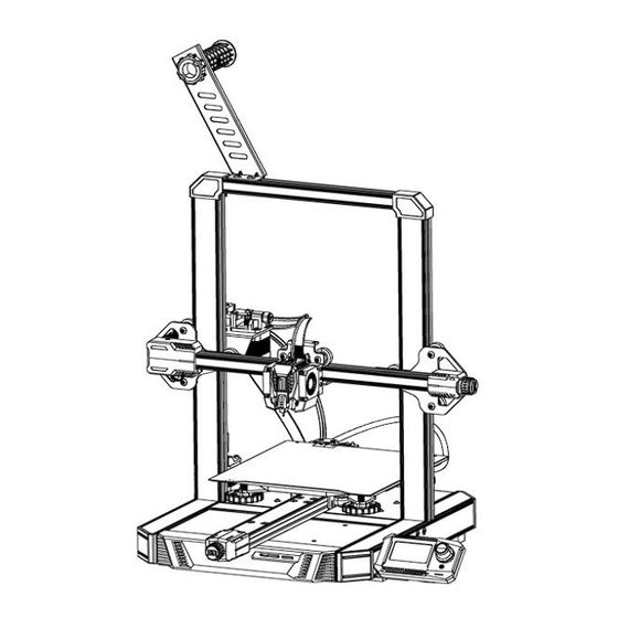
3 Installation Step 1 Remove the motor from the gantry: ①: M4X16 Flat Head Countersunk Screw (2pcs) ②: Lead Screw Sleeve (1pc) Step 2 Put the X-axis module on the gantry: WWW.BIQU3D.COM 5 / 62... - Page 6 ①: Pay attention to the direction, there are two M4 holes. The POM wheels on both sides are aligned with the Z-axis aluminum part. If it is too tight or too loose, the eccentric nut can be adjusted with a wrench so that the POM wheels on both sides of the Z-axis do not shake and are not too tight.
- Page 7 Step 4 Mount the gantry on the machine base: ①: M5X40 Socket Head Cap Screw (4pcs) Step 5 Install the filament bracket: WWW.BIQU3D.COM 7 / 62...
- Page 8 ①: M4X8 Button Head Cap Screw (2pcs) ②: M4 T-nut (2pcs) ③: M4 Washer (2pcs) Loosen the T-nut slightly, then place the filament bracket at the slot on the top, and finally tighten the screw with a screwdriver. The T-nut will rotate slightly during the tightening process to make itself stuck in the aluminum profile slot to fix the filament bracket.
- Page 9 ①: Z-axis Motor Cable → 6P Terminal with "Z" Label ②: Extruder Motor Cable → 6P Terminal with "E" Label ③: Filament Runout Detection Module Cable → 3P Terminal with "E" Label ④: X-axis Motor Cable → 6P Terminal with "X" Label ⑤: X-axis Limit Switch Cable →...
- Page 10 ⑦: Screen Cable 1 → 10P Terminal with "EXP1" Label ⑧: Screen Cable 2 → 10P Terminal with "EXP2" Label ⑨: Cable Ties for Cable Management In the image above, install the terminal to the corresponding position. Step 8 Install the PTFE tube: ①: PTFE Tube (1pc) Push the PTFE tube in until it can no longer be inserted.
-
Page 11: Tuning
4 Tuning Adjust the Eccentric Nut If it is found that the machine is too tight or too loose (there is a shaking phenomenon) during the movement, you can adjust its tightness by adjusting the eccentric nuts of X, Y, and Z with a wrench. - Page 12 4.2 Check Household Voltage Voltage Mode: 115V(Switch to right, you will see 115V marked on the switch), corresponding to Household Voltage: 100—120V; Voltage Mode: 230V(Switch to left, you will see 230V marked on the switch), corresponding to Household Voltage: 200—240V. Before turning it on, check whether the voltage mode of the power supply matches your household voltage.
-
Page 13: Check Household Voltage
screwdriver to toggle the switch to select the mode that matches your household voltage. Make sure that each terminal is fixed firmly and the wiring is correct, then power on the machine. 4.3 Screen Introduction ①: Reset Button: Reset button for the motherboard control system. - Page 14 After the installation of the BIQU-Hurakan is completed, a platform leveling is required. Tram the print bed with the following procedure: Control——Home All——Manual Level——Clear Mesh 14 / 62 WWW.BIQU3D.COM...
- Page 15 After Clear Mesh, we can start manual leveling, place a piece of A4 paper between the nozzle and print bed, adjust the bed height of each corner of the print bed with the thumbscrew until you can feel slight resistance when moving the A4 paper back and forth (Note: this is not to adjust the nozzle height, nozzle height will be adjusted via Z offset in your config):...
- Page 16 16 / 62 WWW.BIQU3D.COM...
-
Page 17: Insert Filament
4.5 Insert Filament Cut the filament tip pointy, hold down the extruder handle, and push the filament into the extruder into the filament tube at the same time. Note: Check whether the screws on the machine are installed correctly, and make sure they are tight. 4.6 Tuning of Nozzle Height Enter the secondary interface during printing: Tune——Offset Z:0.000... - Page 18 Offset: The right height of the nozzle: A right distance between the nozzle and the bed: the filament sticks sufficiently well to the bed. The nozzle is too high from the bed: filament curls and does not lay around nozzle, stick sufficiently well to the bed.
-
Page 19: Printing Preparation
The nozzle is too close to the bed: The nozzle or bed may be damaged. 5 Printing Preparation 5.1 Cura Installation Link: https://ultimaker.com/software/ultimaker-cura Download, install and open the latest version of Ultimaker Cura: 5.2 Cura Slicer Setting Setup the slicer according to the following steps: WWW.BIQU3D.COM 19 / 62... - Page 20 20 / 62 WWW.BIQU3D.COM...
- Page 21 WWW.BIQU3D.COM 21 / 62...
-
Page 22: Cura Slicing
5.3 Cura Slicing Drag and drop the model file you want to print into Cura: 22 / 62 WWW.BIQU3D.COM... - Page 23 In the printer that you have set up, slice the model using the stock settings(or import your own settings if you are an advanced user), click slice and save to your desired folder. WWW.BIQU3D.COM 23 / 62...
- Page 24 24 / 62 WWW.BIQU3D.COM...
- Page 25 WWW.BIQU3D.COM 25 / 62...
-
Page 26: Printing
6 Printing Note: DO NOT remove the MicroSD card when the machine is powered on, the firmware is stored on the Micro SD card, if you remove the SD Card, the following can and will happen: 1. The machine will freeze immediately. 2. - Page 27 Transfer the gcode into the gcode folder: Step 2 Insert Micro SD and power the machine on again. Step 3 Select the gcode file. SD Card——BB1_boat.gcode——Start Printing WWW.BIQU3D.COM 27 / 62...
- Page 28 The nozzle and the heated bed start to warm up, and when the temperature reaches the preset temperature, the machine starts printing. The nozzle and heated bed will cool down after the print is finished, remove the print after the PEI spring steel sheet has cool down.
-
Page 29: Print Via Wifi Network
6.2 Print via WiFi Network Control the printer using a web interface by connecting to the corresponding IP address. Step 1 Set the WIFI ssid and password. (Note: your control device and the printer need to be connected to the same WiFi). Make sure the machine is powered down, remove the MicroSD card and modify the system.cfg file in your computer with the windows default notepad program:... - Page 30 WIFI_SSID="WIFI name" WIFI_PASSWD="WIFI password" Save the file. (Note: No setup is required if the printer is using a wired network) Step 2 Insert the MicroSD card and power on the machine. Click the rotary knob and scroll to the bottom to check the IP address: Enter the IP address in your browser: 192.168.0.92: 30 / 62...
- Page 31 Upload the gcode file: Select the file and click print: WWW.BIQU3D.COM 31 / 62...
-
Page 32: Print Via A Usb Drive
The print will start after the components reached the printing temperature. 6.3 Print via a USB Drive Transfer the gcode file into the USB Drive folder: Plug the USB drive into the corresponding port of the printer. Select the gcode file. SD Card——usb-sda1/BB1_boat.gcode——Start Printing 32 / 62 WWW.BIQU3D.COM... - Page 33 The print will start after the components reached the printing temperature. WWW.BIQU3D.COM 33 / 62...
-
Page 34: Other Function
7 Other Function 7.1 MicroProbe Calibration If you find the MicroProbe factory offset is incorrect, or you have rewritten the system, the steps for calibration are as follows: Setup—Calibration——Start Probing——Move Z( adjust the )——Test distance between the nozzle and bed: ± 1mm adjust the distance between the nozzle and bed: -0.1mm to )——Accept &... - Page 35 Make sure the distance between the bed and the nozzle is between 0 and 0.1mm. WWW.BIQU3D.COM 35 / 62...
- Page 36 If Move Z cannot be adjusted, you can adjust Test Z for more precise fine-tuning. 36 / 62 WWW.BIQU3D.COM...
- Page 37 Make sure the distance between the bed and the nozzle is between 0 and 0.1mm. Back to previous interface. WWW.BIQU3D.COM 37 / 62...
-
Page 38: Auto Leveling
Accept & Save, then we can start auto leveling. 7.2 Auto Leveling Control——Bed Mesh&Save 38 / 62 WWW.BIQU3D.COM... - Page 39 The running track of the printhead during bed mesh: Wait for the finish, the printer will automatically save the config, and return to the main interface. WWW.BIQU3D.COM 39 / 62...
-
Page 40: On/Off Of The Filament Runout Detection Module
7.3 ON/OFF of the Filament Runout Detection Module 40 / 62 WWW.BIQU3D.COM... -
Page 41: For Expansion Module
7.4 For Expansion Module ①: Power Selection for Heated Bed The heated bed switch can switch between two heating powers. (The red light is on for 100W. Both the red and blue lights are on for 240W) ② ADXL345 Interface ③... - Page 42 42 / 62 WWW.BIQU3D.COM...
- Page 43 The default resolution of CURA is 32*32 (you can adjust it according to the display effect). Then use Cura to slice and upload to the web. WWW.BIQU3D.COM 43 / 62...
- Page 44 ADXL345 Resonance Compensation Calibration Install on X Axis Printhead Loosen the screw M3x6 securing the lower right corner of the printhead. 44 / 62 WWW.BIQU3D.COM...
- Page 45 ①: Printhead (1Pc) ②: Button Head Cap Screw M3x6 (1Pc) ③: ADXL345 Module (1Pc) Install the fixing hole of the lower end of the ADXL345 module in the position where the screw was just removed. Note: the centerline of the two fixing holes of the ADXL345 module should be perpendicular to the heated bed WWW.BIQU3D.COM 45 / 62...
- Page 46 platform. ④: Centerline of the Two Fixed Holes of the ADXL345 Module Adjust the position and fix it with M3x6 screws. 46 / 62 WWW.BIQU3D.COM...
- Page 47 Wiring ①: ADXL345 Cable (1Pc) ②: ADXL345 Module Interface ③: ADXL345 Interface on Printer Connect the ADXL345 Module with the printer with the ADXL345 Cable. WWW.BIQU3D.COM 47 / 62...
- Page 48 48 / 62 WWW.BIQU3D.COM...
- Page 49 X Axis Calibration Reference: https://www.klipper3d.org/Measuring_Resonances.html Note: The printer needs to be Home before calibration. Enter the X axis calibration command at the command line: SHAPER_CALIBRATE AXIS=X Note: it will vibrate in the X axis at this time. Please observe the printer first to ensure that the vibration is not too strong. WWW.BIQU3D.COM 49 / 62...
- Page 50 (The test can be aborted in case of emergency). After calibration, enter the save code: SAVE_CONFIG Then power off the printer and remove the ADXL345 module. 50 / 62 WWW.BIQU3D.COM...
- Page 51 Install on Y Axis Heated Bed Loosen the screw M3x10 on the left side of the heated bed cable plastic part. ①: Phillips Flat Head Countersunk Screw M3x10 (1Pc) ②: Heated Bed Cable Plastic Part (1Pc) ③: ADXL345 Module (1Pc) ④: Centerline of the Two Fixed Holes of the ADXL345 Module WWW.BIQU3D.COM...
- Page 52 Install the left fixing hole of the ADXL345 module in the position where you just removed the screws. Note: the centerline of the two fixed holes of the ADXL345 module should be perpendicular to the Y axis. Adjust the position and fix it with M3x10 screws. 52 / 62 WWW.BIQU3D.COM...
- Page 53 WWW.BIQU3D.COM 53 / 62...
- Page 54 Wiring ①: ADXL345 Cable (1Pc) ②: ADXL345 Interface on Printer ③: ADXL345 Module Interface Connect the ADXL345 Module with the printer with the ADXL345 Cable. 54 / 62 WWW.BIQU3D.COM...
- Page 55 Y Axis Calibration Note: The printer needs to be Home before calibration. Enter the Y axis calibration command at the command line: SHAPER_CALIBRATE AXIS=Y Note: it will vibrate in the Y axis at this time. Please observe WWW.BIQU3D.COM 55 / 62...
- Page 56 the printer first to ensure that the vibration is not too strong. After calibration, enter the save code: SAVE_CONFIG Then turn off the printer, remove the ADXL345 module, and restart the printer to finish debugging. 56 / 62 WWW.BIQU3D.COM...
-
Page 57: Faq
8 FAQ Question 1 Print offset in some places: Printing too fast. Answer 1 Recommended speed: 60~80mm/s. The timing belt/timing pulley may be loose, please re-tighten it. Synchronous motor lost steps. The current for the motor is not high enough and the output torque of the motor is insufficient. - Page 58 and use the pliers to make the filament tip Answer 3 pointy. The filament drive gear is too tight, adjust it to make an appropriate tightness. There is residue in the heat break. Please preheat it to 230℃, then push and squeeze out the residue manually.
- Page 59 Question 4 Warping: The distance between the nozzle and the bed is too far, adjust the distance. The cooling of the nozzle outlet is Answer 4 insufficient, please make sure that the fan is working properly. Provide a closed environment to keep the temperature stable.
- Page 60 smoothly, some lubricant may be applied. Question 7 The extruder makes an abnormal sound of "Ka Ka Ka" during printing: It may be that the nozzle is blocked, use a needle to unclog it. Answer 7 The quality of the filament is not high, you can try another filament.
- Page 61 Question 8 The extruded filaments look uneven or have different thicknesses: Check if the filament is jammed or tangled. Answer 8 Check whether the nozzle is blocked. Wrong settings on the layer height or on the filament width. Filaments are of poor quality. Question 9 Stringing: Try increasing the retraction distance by...
-
Page 62: Caution
9 Cautions 1. Do not touch the printhead and the heated bed when the printer is working to avoid burns. 2. Do not touch the spring steel plate when the printer is working to avoid burns. 3. Do not place the printer in a place with great vibrations, which will affect the quality of the prints.
Need help?
Do you have a question about the BIQU-Hurakan and is the answer not in the manual?
Questions and answers