Advertisement
March 15, 2004
A. SYSTEM DESCRIPTION
(Refer to Figure 1 or 2, Page 425 d)
®
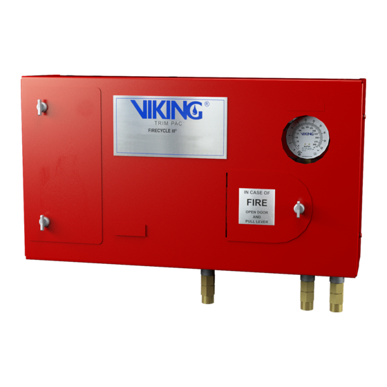
The Viking Firecycle
III Cycling Single
Interlocked Preaction System utilizes a
Viking Model H or J Flow Control Valve
(A.1), a Viking Easy Riser™ Check
Valve (A.2), and a Firecycle
Panel (E.3), together with additional
valves, devices and trim to form a
unique operating system. The system
piping is normally dry and may be in-
stalled in locations subject to freezing.
The system piping is pneumatically
pressurized (Minimum 30 psi (207 kPa))
to monitor the integrity of the piping, fit-
tings and sprinklers and to act as a
fail-safe emergency backup to the elec-
trical detection system.
In addition to automatically detecting a
fire
and
turning
the
®
Firecycle
III has the added ability to
sense when the fire has been controlled,
and automatically turn off the water flow
once a preprogrammed "Soak Timer"
has been satisfied. Should the fire rekin-
®
dle, Firecycle
III will initiate the se-
quence again. This unique cycling fea-
ture will repeat as long as power is avail-
able to the panel, helping to minimize
water usage, water damage, and the
danger of pollution to surrounding areas.
Batteries are available to provide up to
ninety (90) hours of emergency power.
If the A.C. Power fails and the battery
backup power expires while the system
is operating, the deluge system will
"fail-safe", and continue flowing until
A.C. Power is restored or the system is
manually shut-off.
®
The Firecycle
III Cycling Single Inter-
locked Preaction system has several
"fail-safe" features, some of which are
not available on other preaction sys-
tems. Refer to Section B "System Oper-
ation" for details.
Preaction systems are commonly used
to help minimize accidental water dam-
age and still provide fast water dis-
charge during a fire emergency. Consult
all Authorities Having Jurisdiction prior
®
to installing a Firecycle
System. The system requires use of a
Viking Flow Control Valve and trim kit
with two electric Release Solenoid
Valves (E.1) and (E.2) controlled by the
®
Firecycle
III Control Panel (E.3),
®
Firecycle
Detectors (E.4) and Detector
Cable (E.5). The detector temperature
must be lower than the lowest tempera-
ture rated sprinkler being used.
proper location, spacing and positioning
of detectors, refer to Technical Data de-
®
scribing Viking Firecycle
Detectors.
Form No. F_100496
SYSTEM DATA
NOTE:
Firecycle
is listed as a unit. As such, it is normally
not possible to modify the components
of
the
inter-relation without compromising the
listing.
®
III Control
Approvals:
UL Listed, Category VLLA
FM Approved
Accepted for use by City of New York
Department of Buildings,
MEA 89-92-E Vol. XIV
B. SYSTEM OPERATION
(Refer to Figure 1 or 2, Page 425 d.)
In the SET condition:
System water supply pressure enters
the priming chamber of the Flow Control
Valve (A.1) through the 1/4" (8 mm)
system
on,
priming line which includes a normally
open priming valve (B.1), strainer (B.2),
restricted orifice (B.3) and check valve
(B.4). In the SET condition, water supply
pressure is trapped in the priming cham-
ber by check valve (B.4), normally
closed Emergency Release (B.11),
Pneumatic Actuator (B.6), and normally
closed Release Solenoid Valve #1 (E.1).
Water Supply pressure in the priming
chamber holds the clapper of the Flow
Control Valve (A.1) on the seat due to
the differential design of the valve and
spring pressure. The clapper separates
the inlet chamber from the outlet cham-
ber, keeping the outlet chamber and
system piping dry.
In Fire conditions:
When the Firecycle
(E.4 and E.5) operates, the Firecycle
Control Panel (E.3) activates a piezo
sounder and energizes normally closed
Release Solenoid Valve #1 (E.1) open
and normally open Release Solenoid
Valve #2 (E.2) closed. Pressure is re-
leased from the priming chamber faster
than it is supplied through restricted ori-
fice (B.3). The Flow Control Valve (A.1)
clapper opens to allow water to flow into
the system piping and to alarm devices,
causing Alarm Pressure Switch (C.1) to
III Preaction
activate. Water entering the system op-
erates and hydraulically latches the
Pressure
(PORV) (B.10) open. Water will flow
from any open sprinklers or nozzles.
Water discharges until all Firecycle
tectors have reset. (cooled below their
set point). After all detectors have reset,
For
AIR PRESSURE SETTINGS
Water
0-175
175-250
®
III is a complete system, and
system
controls
or
their
®
III detection system
Operated
Relief
Valve
®
System
Detection
Detection
Air
Circuit #1
Circuit #2
30+
25
30
50+
40
50
Replaces page 425a-d dated April 28, 2000. (Added reference to
straight through valves and added air pressure setting chart.)
FIRECYCLE
CYCLING SINGLE
INTERLOCKED PREACTION
®
the Firecycle
III Control Panel (E.3) ac-
tivates the "Soak Timer", allowing the
system to continue discharging water for
a preset time period. When the "Soak
Timer" has expired, the Firecycle
Control Panel (E.3) de-energizes nor-
mally closed Release Solenoid Valve #1
(E.1), allowing it to close. (The normally
open Release Solenoid Valve #2 (E.2)
remains energized closed until the
®
Firecycle
III Control Panel is manually
reset, or both A.C. Power and battery
backup have failed.) The Flow Control
Valve (A.1) re-primes and closes, stop-
ping the flow of water through the sys-
tem piping.
Should a Firecycle
alarm, the Firecycle
(E.3) re-energizes normally closed Re-
lease Solenoid Valve #1 (E.1) open, and
the entire cycle repeats.
To return the system to "Normal" condi-
tions, drain the system piping and re-
place any sprinklers which may have op-
erated. Relieve the pressure on the
Pressure
Operated
(PORV) (B.10) by draining the outlet
chamber of the Flow Control Valve.
(A.1) Replace any Firecycle
which
have
been
re-establish system air pressure. Press
the "System Reset" button on the
®
Firecycle
III Control Panel (E.3) to clear
all alarms.
Trouble conditions:
If the system piping and/or the sprinklers
are damaged and either the AC Power
and/or Standby Battery Power is avail-
able, the low air supervisory switch will
®
III
activate a trouble alarm at the Firecycle
III Control Panel (E.3).
If the detection system is damaged or
malfunctions, the Firecycle
Panel will go into alarm and the Flow
Control Valve will open. Water will fill the
For Technical Data,
Installation, Maintenance
and Testing Instructions for
individual system
components, refer to
current Viking
Technical Data describing
individual components
De-
of the system used.
Viking Technical Data may be
found on The Viking
Corporation's Web site at
http://vikingcorp.com.
The Web site may include a more
recent edition of this
Technical Data Page.
®
Firecycle
III 425 a
®
III
®
III
®
Detector go into
®
III Control Panel
Relief
Valve
®
Detectors
damaged
and
®
®
III Control
Advertisement
Table of Contents

Related Manuals for Viking FIRECYCLE III


Summary of Contents for Viking FIRECYCLE III
- Page 1 Interlocked Preaction System utilizes a ® system controls their Timer” has expired, the Firecycle Viking Model H or J Flow Control Valve inter-relation without compromising the Control Panel (E.3) de-energizes nor- (A.1), a Viking Easy Riser™ Check mally closed Release Solenoid Valve #1 listing.
- Page 2 C. To return to service immedi- Valve and other system components are ® 4. Restore AC power to Firecycle ately, (when no maintenance or packed with product and in the Viking Control Panel (E.3). Ensure that repairs are required) : Engineering Design Data book.
- Page 3 Technical Data describing individ- not reset the Emergency Release or ® 12. Fully open and secure the Main Wa- ual components of the Viking Firecycle manual pull station used or the system ter Supply Control Valve. (D.1) III System.
- Page 4 ® Firecycle III 425 d March 15, 2004 ® FIRECYCLE SYSTEM DATA CYCLING SINGLE INTERLOCKED PREACTION Figure 2 Figure 1 Replaces page 425a-d dated April 28, 2000. (Added reference Form No. F_100496 to straight through valves and added air pressure setting chart.)
Need help?
Do you have a question about the FIRECYCLE III and is the answer not in the manual?
Questions and answers