Table of Contents
Advertisement
Quick Links
Instructions
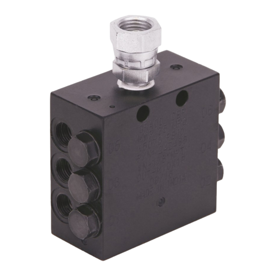
CSP Valve
For the progressive delivery of mineral oil and grease for lubrication. For professional use
only.
5076 psi (35 MPa, 350 bar) Maximum Operating
Pressure
See page 3 for model information, including maximum
working pressure and approvals.
Important Safety Instructions
Read all warnings and instructions in this
manual before using the equipment.
Save all instructions.
Related Manuals
Manual in
Description
English
3A3159
Field Attachable Hose Fittings
Without Indicator Pin
With Indicator Pin
3A3995L
EN
Advertisement
Table of Contents

Related Manuals for Graco CSP Series


Summary of Contents for Graco CSP Series
-
Page 1: Related Manuals
Instructions CSP Valve 3A3995L For the progressive delivery of mineral oil and grease for lubrication. For professional use only. Without Indicator Pin 5076 psi (35 MPa, 350 bar) Maximum Operating Pressure See page 3 for model information, including maximum working pressure and approvals. Important Safety Instructions Read all warnings and instructions in this manual before using the equipment. -
Page 2: Table Of Contents
Installation....... . . 5 Graco Standard Warranty....22 Setup . -
Page 3: Models
Models* Models* *Lubricant output for these models: 0.2 cc per outlet and per stroke No. of Indicator Model Series Inlet Outlets Included 24Z477 1/8 in. bspp 24Z478 1/8 in. bspp 24Z479 1/8 in. bspp 24Z480 1/8 in. bspp 24Z481 1/8 in. bspp 24Z482 1/8 in. -
Page 4: Warnings
Warnings Warnings The following warnings are for the setup, use, grounding, maintenance, and repair of this equipment. The exclamation point symbol alerts you to a general warning and the hazard symbols refer to procedure-specific risks. When these symbols appear in the body of this manual or on warning labels, refer back to these Warnings. Product-specific hazard symbols and warnings not covered in this section may appear throughout the body of this manual where applicable. -
Page 5: Installation
NOTE: The output volume of a CSP valve outlet can be • Always use Graco provided block outlet fittings increased by installation of a doubling plug (17L651) with clamping ring in block outlet. Any fittings with- into an adjacent outlet. The doubling plug causes the... -
Page 6: System Monitoring
Installation System Monitoring Proximity Switch Kits In a series progressive system, the primary and sec- NOTE: Available only for CSP valves with an indicator ondary CSP valves can be connected with high pres- pin. sure hoses so every outlet is linked together. 26C822 Switch, PNP, 9.5 in. - Page 7 Installation When using the cylindrical adapter (F . 4): 3. Mount the proximity switch assembly to the CSP valve. 1. Apply user supplied thread adhesive to the threads. • For Series A CSP Valves: torque to within 25 to 30 ) (F .
-
Page 8: 26C823 Flying Lead
Installation Wiring Instructions NOTICE The electrical ratings for the system must not be exceeded. Overloading the switch can cause it to fail on the first cycle. 26C823 Flying Lead 26C822 M12 Connector Pin Out 3A3995L... -
Page 9: Operation
Operation Operation Pressure Relief Procedure Overview Follow the Pressure Relief Procedure whenever • Lubricant supply can either be continuous or inter- you see this symbol. mittent. • Every movement of the plunger delivers a fixed quantity of lubricant. • The cycle repeats as long as lubricant is supplied to the inlet port. -
Page 10: Sequences
Operation Sequences Sequence 1 1. Lubricant enters through the inlet provided at the Inlet top of the block. 2. Lubricant fills the left side of Plunger 1 pushing the plunger to the right. 3. Plunger 1 opens, delivering lubricant to Outlet 1 . -
Page 11: Sequence 3
Operation Sequence 3 1. Lubricant fills the left side of Plunger 3 pushing the Inlet plunger to the right. 2. Plunger 3 opens, delivering lubricant to Outlet 6 . 12). Outlet . 12 Sequence 4 1. Lubricant fills the right side of Plunger 1 pushing Inlet the plunger to the left. -
Page 12: Sequence 5
Operation Sequence 5 1. Lubricant fills the right side of Plunger 2 pushing Inlet the plunger to the left. 2. Plunger 2 opens, delivering lubricant to Outlet 3 . 14). Outlet . 14 Sequence 6 1. The final sequence completes the cycle. Lubricant Inlet fills the right side of Plunger 3. -
Page 13: Blockages
Consult your lubricant supplier for recommen- Higher pressure is limited, isolated, and signaled dations on alternate lubricants and your local Graco through the use of various performance indicators, distributor to verify compatibility with centralized lubri- reset and relief, incorporated into the system design. -
Page 14: Recycling And Disposal
Recycling and Disposal Recycling and Disposal End of Product Life At the end of the product’s useful life, dismantle and recycle it in a responsible manner. • Perform the Pressure Relief Procedure, page 9. • Drain and dispose of fluids according to applicable regulations. -
Page 15: Kits And Accessories
17Y693★ check valve, 5076 psi (35 MPa, 350 bar) bar) Fitting, push to connect, 6 mm stud x ◆ Always connect fittings to Graco designed stud to 17Y689 1/8 npt male, straight, 2000 psi (13.79 ensure connections. MPa, 137.9 bar) - Page 16 Kits and Accessories . 16 3A3995L...
-
Page 17: Lubrication Point Fittings (English Threads)
17T783 male 90°, 3000 psi (20.68 MPa, 206.8 MPa, 206.8 bar) bar) FITTING, compression,6 mm x M6 ◆ Always connect fittings to Graco designed stud to 17R574 tapered male 90°, 3000 psi (20.68 ensure connections. MPa, 206.8 bar) FITTING, compression, 6 mm x M8 ‡... -
Page 18: 1/8 In. Id Hose End Fittings
Kits and Accessories 1/8 in. ID Hose End Fittings (connect to 1/4 6 MM OD Nylon Tube in. PTC fittings) ◆ Maximum working pressure - 1000 psi (6.9 MPa, 69 bar) Maximum working pressure - 3000 psi (20.68 MPa, 206.8 bar) Part No. -
Page 19: Block Installation Kit
Kits and Accessories Block Installation Kit Proximity Switch Kit Only available for CSP valves with an indicator pin. Part No. Description 26A478* KIT, weld stud Part No. Description STUD, M6 x 45 26C822 Switch, PNP, 9.5 in. (24 cm) Cable with M12 connector NUT, M6, lock 26C823... -
Page 20: Dimensions
Dimensions Dimensions *This dimension varies and is determined by the number of outlets. See No. of Outlets, page 21 for this dimension. 3A3995L... -
Page 21: Technical Specifications
Technical Specifications Technical Specifications CSP Valve Metric Type Divider valve Model See Models, page 3 Lubricant Output (per outlet, per cycle) 0.2 cc 0.012 in. Minimum Operating Pressure 350 psi 24.1 bar, 2.41 MPa Maximum Operating Pressure 5076 psi 350 bar, 35 MPa Inlet Connection Size 1/8 in. -
Page 22: Graco Standard Warranty
With the exception of any special, extended, or limited warranty published by Graco, Graco will, for a period of twelve months from the date of sale, repair or replace any part of the equipment determined by Graco to be defective.
Need help?
Do you have a question about the CSP Series and is the answer not in the manual?
Questions and answers