
Related Manuals for Interscan Corporation 4000 Series


Summary of Contents for Interscan Corporation 4000 Series
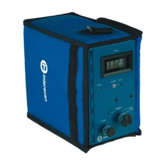
- Page 1 Interscan Corporation Instruction Manual 4000 Series Compact Portable Analyzer 1.800.544.2843 www.calcert.com sales@calcert.com...
-
Page 2: Table Of Contents
INTERSCAN CORPORATION 4000 SERIES MANUAL TABLE OF CONTENTS TABLE OF CONTENTS SECTION TITLE PAGE Equipment Description General Information Operating Instructions Special Instructions Calibration General Maintenance Troubleshooting Warranty Parts List 10.0 Schematics 11.0 Return Authorization 12.0 Index - II - 1.800.544.2843 www.calcert.com... -
Page 3: Equipment Description
Section Equipment Description Front Panel Designation Function ALARM LIGHT: Lamp. Flashes ON/OFF when alarm set point is exceeded. ALARM SET: 25-Turn potentiometer with a screwdriver adjustment. Sets the alarm trip point at the desired PPM level. A LCD is provided on some models. AUIDIBLE ALARM: Horn. - Page 4 Rear Panel Designation Function INLET: ¼” OD compression gas fitting. OUTLET: ¼” OD compression gas fitting RECORDER OUTPUT: ¼” phone jack for #4990-B-36 recorder output cable. WARNING: DO NOT CONNECT TO A RECORDER IF IN A HAZARDOUS ATMOSPHERE. CHARGER INPUT: 3.5mm phone jack for 9V DC, 100mA charger input.
-
Page 5: General Information
General Information See Section 4.0 for Special Instructions 2.1 Monitor Description The INTERSCAN 4000 Series Portable Analyzer is a direct-reading, battery -operated unit with integral sample pump. The detection element is an electro-chemical voltametric sensor, designed for long term, reliable performance. - Page 6 The INTERSCAN sample-draw sensor is a high sensitivity detector with sensitivity 50 to 200 times greater than a diffusion-mode sensor, depending on the gas type. A much lower minimum detectability is possible… an important requirement for measuring gas that has a low TLV. Principle of Operation The INTERSCAN voltametric sensor (U.
-
Page 7: Operating Instructions
Section Operating Instructions See Section 4.0 for Special Instructions Your INTERSCAN monitor has been calibrated at the Factory and is ready for use. 3.0 Inspection Open the box (es) and inspect for damage immediately upon receipt. Examine the Contents list and ensure all items that were shipped have been received. Contact INTERSCAN and report any damaged or missing items immediately. - Page 8 3.2 Setting the Alarm (if applicable) Normally, the alarm is set at the Factory at 50% of full scale. The alarm can be reset to any desired level by following the procedure below. Set FUNCTION switch to ZERO. Select low range on multi-range units. Using the ZERO control, advance the meter to the desired alarm set point.
- Page 9 Nominal sample rate is approximately 1.0 liter per minute, ± 0.2 liter per minute. The Average sample time, starting with fully charged “C” batteries, is 12 hours. If the BATTERY TEST “A” indication is down to 25% of the battery test region, the flow rate may have started to decrease.
-
Page 10: Special Instructions
Section Special Instructions Not Applicable for this Instrument - 8 - 1.800.544.2843 www.calcert.com sales@calcert.com... -
Page 11: Calibration
Section Calibration See Section 4 for Special Instructions Introduction It is not necessary to calibrate the monitor when received from the Factory, or from an INTERSCAN distributor. All INTERSCAN monitors are calibrated at the Factory prior to shipment. Unless the SPAN adjust is inadvertently changed, there is no need to calibrate the monitor until it has seen considerable usage. - Page 12 Calibration is accomplished by quick and simple adjustments of the ZERO and SPAN controls using a digital voltmeter. See the attached information sheet on ECS. Calibration can be particularly difficult in the case of Chlorine and HCl gases which are easily chemisorbed, even by chemically inert tubing.
- Page 13 are unstable, in some cases, in less than a month. INTERSCAN should be consulted for recommendations on commercially available gas mixtures. An alternative source of calibration gas is the use of permeation devices containing the liquefied gas under pressure. Permeation of the gas in nanogram-per-minute rates, permits the generation of a desired concentration in an air or nitrogen carrier.
- Page 14 method to use, and probably the most accurate. The ppm concentration varies directly with the permeation rate, and inversely with the flow rate of the carrier gas. The permeation rate is a logarithmic function of temperature in degrees Celsius. (see Section 5.7) 5.5.1 Auxiliary Equipment Besides the permeation device, an accurate low flow rotameter, cylinder of zero air or...
- Page 15 ppm = P x K The gas concentration is calculated from: 24.46 Where K is and F is the carrier gas flow rate, in ml/min, through the Mol.Wt. permeation device. 5.8 Chemisorbable Gases See Section 4.0 for Special Instructions Chemisorbable and moisture soluble gases, such as Chlorine, HCl and Hydrazine require that the carrier gas used with the permeation device be totally dry.
- Page 16 tubes should not be less than 3 cm of active length. These should last more than 8 months with refrigeration.) This requires bypassing the sensor during the pre-conditioning. Because of degassing, pre-conditioning is not permanent. This chemisorption effect is not serious, because sensor response to changes in gas concentration is always rapid, even during the initial adsorption period.
-
Page 17: General Maintenance
Battery Charging and Replacement All models of the 4000 Series analyzers use two “C” size alkaline batteries. These are located on the hinged door, right side. Polarity is marked on the d oor over the battery holder. - Page 18 accurate meter indication of this point difficult. It is recommended that the batteries be recharged if the meter is in the lower half of the battery test region. The charger is an external 9V DC, 100mA transformer and is connected to the rear of the unit prior to charging.
- Page 19 Long Term Storage (one month or more) Turn FUNCTION switch to “OFF” position. Disconnect charger from instrument. Detach plug-in connector from circuit board. Remove alkaline batteries and cover instrument to protect from dust. Post Storage Start-up 24 Hours Before Using: Uncover the instrument.
-
Page 20: Troubleshooting
Section Troubleshooting A high percentage of service problems often result from little things that you can find and fix yourself. Symptom Corrective Action • Ensure the FUNCTION switch is not in the OFF position. No power. • Are Ni-Cad batteries charged? (See Section 3.1) •... -
Page 21: Warranty
INTERSCAN CORPORATION warrants sensors of its manufacture to be free from defects in material and workmanship for a period of six months from date of shipment. -
Page 22: Parts List
Section Return Authorization All returns for repairs require a "RETURN AUTHORIZATION NUMBER" issued by the INTERSCAN Service Department upon request. This is done primarily to cause the user to contact the factory directly. The reason for this is that a high percentage of service problems are resolved over the telephone, avoiding the need for returning the instrument or part. -
Page 23: Schematics
Section Index Subject Section Alarm Set / Setting the Alarm Battery Charging and Replacement Battery Check Battery Life Calibration, Electronic Calibration Gas Standards Calibration Introduction Calibration Procedures 5.10 Calibration, Sample Bag Calibrators Chemical Scrubbers Chemisorbable Gases Equipment Description INTERSCAN Sensor, The - 23 - 1.800.544.2843 www.calcert.com... -
Page 24: Return Authorization
Subject Section Monitor Description Parts List Permeation Devices Permeation Rate & PPM Calculation Permeation Tube Manufacturers Post Storage Start up Return Authorization 11.0 Sample Pump Flow Control Sampling Schematics 10.0 Sensor Principle of Operation Storage, Long Term Warranty Zeroing the Instrument - 24 - 1.800.544.2843 www.calcert.com...
Need help?
Do you have a question about the 4000 Series and is the answer not in the manual?
Questions and answers