
Related Manuals for Endress+Hauser Mycom CPM 152


Summary of Contents for Endress+Hauser Mycom CPM 152
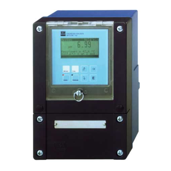
- Page 1 Mycom BA 143C/07/en/08.00 Nr. 50077396 Software version 3.00 CPM 152 Transmitter/Controller for pH and Redox Operating Instructions MEAS DIAG PARAM Endress Hauser The Power of Know How...
- Page 2 Please familiarise yourself with the instrument before you take any other steps: General information Safety Description You want to install and start up the instrument. All the necessary steps can be found in these chapters: Installation First Start-up You want to operate or reconfigure the instrument. The operating concept is explained in these chapters: Operation Instrument configuration...
-
Page 3: Table Of Contents
Electrical connection of Mycom CPM 152 ........ -
Page 4: General Information
Note: This symbol draws attention to important items of information. Conformity statement The pH and redox measuring transmitter Mycom CPM 152 has been developed and manufactured in accordance with current European standards and directives. Note: A conformity statement can be obtained from Endress+Hauser. -
Page 5: Safety
If the version of the Mycom CPM 152 with Since it has been designed to permit explosion protection is chosen, it can be extensive programming and the addition of operated in explosive atmospheres as well. -
Page 6: Description
Description mycom CPM 152 Description Application areas The measuring transmitter Mycom CPM 152 is • Chemical process engineering highly suitable for carrying out measuring and • Pharmaceutical industry control assignments - even in the case of • Food industry difficult control systems - in the following •... -
Page 7: Instrument Versions
By means of the order code on the nameplate and the required power supply. you can identify the instrument version, pH and redox measuring transmitter Mycom CPM 152 Field housing for wall mounting, ingress protection IP 65 basic version with: 2 signal outputs 0 / 4 ... -
Page 8: Accessories
Description mycom CPM 152 (Equipment and certificate, see above) Power supply 230 V, 50 / 60 Hz 115 V, 50 / 60 Hz 200 V, 50 / 60 Hz 24 V, 50 / 60 Hz 100 V, 50 / 60 Hz... -
Page 9: Installation
If you have any questions, please contact Check that the delivery is complete and your supplier or the Endress+Hauser sales corresponds to your order and the shipping agency in your area (see the back of documents: these operating instructions). - Page 10 Mycom CPM 152 Mounting accessories • Flat gasket for panel mounting Order no. 50064975 • Weather protection cover CYY 101 for operating the Mycom CPM 152 outdoors. Material: stainless steel Order code CYY101-A 2 round post attachment kits (see fig. 4.5) are also needed for installation on vertical or horizontal pipes.
-
Page 11: Electrical Connection Of Mycom Cpm 152
CPM 152 Installation pm152e04.chp Electrical connection of Mycom CPM 152 Warning: Caution: • Only appropriately trained • All lines conducting signals are personnel is allowed to work on to be shielded according to the instrument when the system VDE 0165 and run separately is live and is connected to the from other control lines. - Page 12 Installation mycom CPM 152 4.4.1 Connection of Mycom CPM 152 in non-Ex areas F101 250 Vac / 3A ( cos 125 Vdc / 3A pH/mV L L N Temp. Relay L+ L+ L- contact 88 87 85 86 Power 31 32 33 34...
- Page 13 CPM 152 Installation pm152e04.chp Additional module FCP1: for second pH redox input, identical to module FCP1 in the basic version pH/mV pH/redox input 13 12 11 not connected not connected Connection of fcp2con.cdr Ref. Reference Fig. 4.8 module FCP1...
- Page 14 Installation mycom CPM 152 4.4.2 Connection of Mycom CPM 152-Z in Ex areas General instructions about installation in potentially explosive surroundings Instruments with the letter Z (standing for Electrodes (measuring chains) that are “certificate”) in their name have been suitable for the instrument can also be...
- Page 15 88 87 85 86 2x Optocoupler max. 30 Vdc / 100mA / 750mW Power- supply Basic sub-assembly Connection compartment Mycom CPM 152-Z with explosion protection Fig. 4.12 (basic equipment) pH module / redox input Module current input Basic sub-assembly (FCP1 / slot 1)
- Page 16 Installation mycom CPM 152 Basic sub-assembly Electrical properties of contact circuit: max. output voltage , max = 30 V max. output power , max = 750 mW Outputs with npn transistors. The connections of the emitters (E) must have negative potential in relation to the collectors (C).
- Page 17 CPM 152 Installation pm152e04.chp Additional module FCYK-Ex: with 3 optocouplers for controllers and/or Chemoclean Contact 2 Contact 3 Contact 4 Contact 2 plus Contact 2 minus Contact 3 plus Contact 3 minus Contact 4 plus Contact 4 minus Connection of Outputs with npn transistors.
- Page 18 Installation mycom CPM 152 Additional module FCXI: with 2 binary inputs and active analogue input (measuring transmitter supply) Analogue current input plus Analogue current input minus Analogue input Input 1 Input 2 Binary input 1 plus Binary input 1 minus...
-
Page 19: Connection Of Ph And Redox Electrodes
CPM 152 Installation pm152e04.chp Connection of pH and redox electrodes Ref. Coax bk CPK 1 pH / redox pH / redox Outer screen CPK 6-S PE ye/gn Application: Coax rd pH (circuit 1) Sensopac CPA 320 pH (circuit 2) Coax wt Ref. - Page 20 Installation mycom CPM 152 4.5.2 Symmetrical or asymmetrical connection of electrodes? Caution: If asymmetrical measurement is The instrument has been configured required, the configuration has to for symmetrical measurement be changed accordingly (with potential matching, PM). (see chapter 7.1.1). ϑ...
-
Page 21: Removal, Packaging And Disposal
CPM 152 Installation pm152e04.chp 4.5.3 Connection accessories Extension cables CYK 71 10.2 Extension cables: CYK 71 (for CPK 1, 7, 9) Fig. 4.25 and DMK (for CPK 6) CYK-DMK.CDR Junction box VBA This junction box is required for line lengths of more than 20 m between the assembly and the transmitter. -
Page 22: First Start-Up
First Start-up mycom CPM 152 First Start-up Measures before the first power-up Familiarise yourself with the operation of the measuring transmitter before switching it on for the first time! (chapter 6) Caution: Warning: Make sure all connections have Before power-up, make sure that... - Page 23 CPM 152 First Start-up pm152e05.chp Set-up guide / checklist Question Possible choices Factory settings User settings chapter Language version A: Deutsch, English, Français, Italiano Language 7.1.4 Language version C: English Deutsch, English, Français, Nederlands, Japanese Contrast of the 7.1.4...
-
Page 24: Operation
Operation mycom CPM 152 Operation Operating elements Liquid crystal display green: normal operation MEAS 4 keys for red: acute fault instrument configuration DIAG PARAM 4 keys for calling up LED with no function the main groups Operating elements PM152E07.CDR Fig. 6.1... -
Page 25: Key Functions
• Return to a more general menu Operating concept The functions of the measuring transmitter Note: Mycom CPM 152 are divided into four main groups: You can refer to a summary of the Mycom menu structure on the last • Measurement pages of these operating •... - Page 26 Operation mycom CPM 152 Note: • It is possible to change to a diffe- • If there is no input in a sub-group rent main group even when you for more than 10 minutes, the are in the middle of a sub-group.
-
Page 27: Different Kinds Of Possible Measurement Displays
Different kinds of possible measurement displays Depending on the nature of the measurement, The current pH or redox current output the measuring transmitter Mycom CPM 152 reading is always displayed in the top offers up to six different kinds of possible right-hand line. - Page 28 Operation mycom CPM 152 Redox absolute (mV) 1. Main display: redox potential channel 1 (large) Additional info: none 2. Main display: redox potential channel 1 Single-circuit Additional info: none 3. Main display: redox potential channel 1 Additional info: measured temperature channel 1 if necessary contact statuses if necessary 1.
-
Page 29: Access Codes
CPM 152 Operation pm152e06.chp Access codes Functions can be protected by four-digit access codes to make sure no unintentional or undesirable changes are made to the configuration and calibration data of the measuring transmitter. The release status of the functions is divided up into operator and advanced level. -
Page 30: The "Short-Cut To Relays" Menu
Operation mycom CPM 152 The “short-cut to relays” menu → Short-cut to relays PARAM The short-cut to relays menu gives you direct Note: access to the main functions without having to go through the whole of the configuration Functions which are not available or menu. -
Page 31: Hold And External Control Inputs
CPM 152 Operation pm152e06.chp Hold and external control inputs 6.8.1 Hold function, freezing the outputs In order to avoid unintentional changes to the See: current outputs or controller contact positions during configuration or calibration, the • Chapter 6.7, short cut to relays menu, present status can be “frozen”... - Page 32 Operation mycom CPM 152 External control in the case of a connected retractable assembly (for adjustment see chp. 7.1.3, »relays allocation«) Binary input 1 Binary input 2 External hold Action (81 / 82) (83 / 84) Move assembly into measuring...
-
Page 33: Instrument Configuration
CPM 152 Instrument configuration pm152e07.chp Instrument configuration Note: • You can refer to a summary of the Mycom menu structure on the last page of these operating PARAM instructions. • Most of the parameter functions are only available with the election »specialist«. -
Page 34: System Set-Up
Instrument configuration mycom CPM 152 System Set-up → Commissioning PARAM → System set-up → Parameter 7.1.1 → Pass codes 7.1.2 → Output relays 7.1.3 → General settings 7.1.4 7.1.1 Parameter Function Selection Default Operating mode redox absolute (mV), redox relative (%) - Page 35 CPM 152 Instrument configuration pm152e07.chp 7.1.2 Pass codes Function Selection Default 0000 ... 9999 0000 Operator code 0000 ... 9999 0000 Advanced code – 7156 Emergency code Note: Refer to chapter 6.6. 7.1.3 Output relays Caution: • Before starting up, check whether •...
- Page 36 Instrument configuration mycom CPM 152 Relays allocation for basic configuration »maintenance« »limit contact / controller« Selection Fault Fault Fault contact Ter. 85/86 Contact 1 Maintenance Limit / control contact Ter. 87/88 Output contact of the non-Ex version in case of power failure (configuration of NO/NC, see start-up menu): active (N.
-
Page 37: Current Output
CPM 152 Instrument configuration pm152e07.chp 7.1.4 General settings Function Selection Default Language version A (see product structure): Deutsch, English, Français, Italiano English Language Language version B (see product structure): Deutsch, English, Français, Nederlands, Japanese Signal damping Number of measurements over... - Page 38 Instrument configuration mycom CPM 152 7.2.2 Current output 1 / 2 With single-circuit measurement the With two-circuit measurement (see 7.1.1): configuration is always as follows: Current output 1: pH / redox (channel 1) Current output 1: pH / redox Current output 2: pH / redox (channel 2) or Current output 2: temperature temperature or diff.
-
Page 39: Temperature Compensation And Medium Temperature Compensation
Medium temperature compensation Tables for three different measuring media The compensation consists of up to ten value can be entered in the Mycom CPM 152 for pairs (temperature and relevant pH level). medium temperature compensation. The appropriate table can be selected as the active medium before the process begins. - Page 40 Instrument configuration mycom CPM 152 Example: Sodium hydroxide 0.1 mol/l ϑ [°C] 13.37 12.96 ϑ = 25 °C 12.75 12.75 12.61 12.29 11.98 11.69 11.43 11.19 ϑ [°C] 10.99 Source: IEC 746-2 NAOH.CDR If a reference temperature of 25 °C is entered (e.g.
- Page 41 CPM 152 Instrument configuration pm152e07.chp Hydrochloric acid 0.1 mol/l ϑ [°C] 1.20 1.08 1.09 1.09 1.10 1.10 1.10 1.11 1.11 1.11 1.00 1.12 1.13 ϑ [°C] Source: IEC 746-2 HCL.CDR Milk of lime ϑ [°C] 12.5 12.4 11.68 12.0 10.8...
- Page 42 Instrument configuration mycom CPM 152 7.3.4 Temperature settings pH Function Selection Default Automatic (ATC) channel 1 Automatic (ATC) channels 1+2 (with 2-circuit measurement only) Automatic Type of temperature compensation (ATC) Manual (MTC), with Pt 100 channel 1 = with additional temp. meas.
-
Page 43: Electrode Monitoring "Scs
CPM 152 Instrument configuration pm152e07.chp Electrode monitoring »SCS« → Commissioning PARAM → Sensor monitoring The sensor check system SCS monitors the The sensor check system SCS can be pH and reference electrode to determine switched on or off in the »Sensor monitoring«... -
Page 44: Preliminary Calibration Settings
Instrument configuration mycom CPM 152 Preliminary calibration settings → Commissioning → Calibration → Calibration parameters 7.5.1 PARAM → General settings 7.5.2 → Buffer selection 7.5.3 → Calibration parameters Redox 7.5.4 → General settings 7.5.5 7.5.1 Calibration parameters (pH) Function Selection... - Page 45 CPM 152 Instrument configuration pm152e07.chp 7.5.3 Buffer selection (pH) Function Selection Default E+H, Ingold; Merck / Riedel; DIN; special buffer type; Buffer type Japan; Fisher; Beckmann; Cole-Parmer; OMEGA If one of the standard buffers is chosen (only relevant for calibration with preset buffer) Selection of buffer 1 6.98...
-
Page 46: Chemoclean
Instrument configuration mycom CPM 152 Chemoclean → Commissioning → Chemoclean PARAM 7.6.1 Areas of application Chemoclean is a system for cleaning It is possible to activate a pneumatic electrodes automatically. It requires an retractable holder in combination with the instrument with an additional FCYK module Autoclean CPC 20 control system. - Page 47 CPM 152 Instrument configuration pm152e07.chp 7.6.3 Cleaning programmes Interval cleaning Hold Holder Water Cleaning agent Cleaning cycle with interval cleaning / Fig. 7.1 week programme A cleaning operation is started when the Start of the cleaning cycle specified interval time to is over. The system ...
- Page 48 Instrument configuration mycom CPM 152 SCS controlled cleaning Additionally to one of the three cleaning Note: programs, the cleaning process can be actuated by the SCS fault messages E030 • The total SCS electrode monitoring and E031 if the »SCS« electrode monitoring is only possible in the case of system is switched on (see Chapter 7.4).
- Page 49 Mycom CPM 152 measuring transmitter Apart from this, the cleaning program is (faults E001 - E023).
-
Page 50: Controller Configuration
/ value and controller always relate output relays« (see chapter 7.1.3). to input 1. Types of controller The Mycom CPM 152 measuring transmitter MAX function has the following controller functions for controlling the pH value: 100 % •... - Page 51 CPM 152 Controller configuration pm152e08.chp Two-range P controllers The two-range P controller is the preferred choice for neutralisation in batch processes. In accordance with the processbased titration curve, the control amplification can be set for 100 % an inner and an outer pH/redox range.
-
Page 52: Instruments With Two Contacts
Controller configuration mycom CPM 152 Three-point step controller control contact 1 »open« 3-point step control contact 2 »close« controller pH/mV CPM 152 Mixing pipe Process control with a Fig. 8.6 three-point step controller Three-point step controllers are used in The adjustable neutral zone makes it possible... - Page 53 CPM 152 Controller configuration pm152e08.chp Function Selection Default If limit contactor 1 »on« Limit value configuration Limit value three configuration groups alarm configuration configuration can be selected. operating mode If »Limit value configuration« is selected Switching limit contact 1 on / off...
- Page 54 Controller configuration mycom CPM 152 Function Selection Default If »parameterize« is selected P controller Control gain : 0.10 ... 20.00 1.00 Min. controller output: 0 ... 50 % Controller output Max. controller output: 50 ... 100 % 100 % Control effect...
-
Page 55: Instruments With Five Contacts
CPM 152 Controller configuration pm152e08.chp Instruments with five contacts → Commissioning PARAM → Relay contacts → Limit contactor 8.3.1 → Control contacts 8.3.2 Note: If limit contactor 1 is selected, it is not possible to set a controller The controllers require either control... - Page 56 Controller configuration mycom CPM 152 Function Selection Default If »Operation mode« is selected Selection of limit contact Limit contact 1, limit contact 2 limit cont. 1 Auto contact 1 / 2 manual Changing operating mode Manual contact 1 / 2...
- Page 57 CPM 152 Controller configuration pm152e08.chp Function Selection Default If »parameterize« is selected Parameter setting for the controller characteristics P, PI, PD and PID is carried out as outlined in chapter 8.2.2 3-point step controller PD or PDT1) Control gain, : 0.10 ...
-
Page 58: Calibration
Calibration mycom CPM 152 Calibration Note: The preliminary calibration settings are made at the main parameter setting level on the menu “Instrument data / calibration” (see Chapter 7.5). A direct route is taken to the relevant calibration routine in accordance with the type of calibration set on the menu “Instrument data / calibration / calibration... - Page 59 CPM 152 Calibration pm152e09.chp Interruption of the calibration operation General calibration instructions The calibration operation can be interrupted Caution: at any time by pressing the MEAS key. • Clean electrode before calibration. • If symmetrical high-impedance electrode connection is chosen,...
-
Page 60: Calibrate Ph
Calibration mycom CPM 152 Calibrate pH • Automatic buffer recognition ( 9.1.1) • Preset buffers ( 9.1.2) Both standard buffers and up to three Two buffer solutions are determined in individually defined buffers can be the “commissioning / calibration / buffer specified in the “commissioning /... - Page 61 CPM 152 Calibration pm152e09.chp Display Description Calibration is being carried out now. The instrument is waiting until the pH measurement has stabilised and will then store the measured value and move on to the calibration information. If the measured value is not stable after 300 seconds a display appears with the option of discontinuing the calibration operation.
- Page 62 Calibration mycom CPM 152 9.1.2 Preset buffers (pH) The same procedure as with calibration with automatic buffer identification (see chapter 9.1.1) is followed in the case of calibration with preset buffers. One difference is, however, that the buffers specified during instrument configuration in the “Calibration”...
- Page 63 CPM 152 Calibration pm152e09.chp Display Description The pH value measured with the old calibration data is displayed. Correct the display by entering the temperature-correct pH value of the buffer you are currently using. Press the E key. If you are calibrating two temperature sensors the instrument will ask you to repeat ↑...
-
Page 64: Calibrate Redox Absolute (Mv)
Calibration mycom CPM 152 9.1.4 Numerical calibration (pH) Display Description Enter the pH value for the electrode zero point. Press the E key. ↑↓→ Enter the electrode slope value in mV / pH. Press the E key. Note: The slope value relates to the set reference temperature. - Page 65 CPM 152 Calibration pm152e09.chp 9.2.2 Calibration absolute (mV) Display Description The redox value measured with the old calibration data is displayed. Wait until the measurement has stabilised. Press the E key to store the measurement. Enter the redox value for the buffer used.
-
Page 66: Calibrate Redox Relative (%)
Calibration mycom CPM 152 Calibrate redox relative (%) • Data entry absolute ( 9.3.1) • Calibration relative ( 9.3.4) Entry of electrode offset in mV. One detoxified and one unchanged sample serve as buffers. • Data entry relative ( 9.3.2) Entry of two % calibration points •... - Page 67 CPM 152 Calibration pm152e09.chp 9.3.3 Calibration absolute (%) Display Description The redox value measured with the old calibration data is displayed. Wait until the measurement has stabilised. Press the E key to store the measurement. Enter the absolute redox value of the buffer in mV.
- Page 68 Calibration mycom CPM 152 9.3.4 Calibration relative (%) A sample of the medium is filled in two The contents of the second container are left containers for calibration purposes. The unchanged and serve as buffer 2. contents of the first container are detoxified and serve as buffer 1.
- Page 69 CPM 152 Calibration pm152e09.chp Display Description If there is a calibration fault you will be informed by a display. Press the E key to return to the start menu. Final menu. You can: store the calibration • repeat the calibration •...
-
Page 70: Profibus Interface
FCYP module In the simplest case, a complete measuring The maximum number of transmitters in one point consists of the Mycom CPM 152 with the bus segment is determined by their current FCYP module (see chapter 4, fig. 4.12), a bus... -
Page 71: Bus Address
CPM 152 PROFIBUS interface pm152e10.chp 10.3 Bus address Each device is assigned a unique bus • Param address: • Advanced • Commissioning ⇒ Set address (1 ... 126) with switches 1-7 • System set-up ⇒ Switch 8 set to OFF: General ⇒... -
Page 72: Remote-Controlled Operation With Commuwin Ii (Acyclical Service)
PROFIBUS interface mycom CPM 152 10.4 Remote-controlled operation with Commuwin II (acyclical service) PROFIBUS-PA devices can be operated via the BA 124F operating instructions. Settings the Commuwin II operating program (starting are made via the operating matrix (see fig. with software version 1.5). A PC with 10.3) or graphical user interface (see fig. - Page 73 CPM 152 PROFIBUS interface pm152e10.chp Establishing the connection Remote control requires installation of the • The appropriate settings are made in the PROFIBUS-PA server, and the PC must be Commissioning menu. equipped with a PROFIBUS-PA interface: • PROFIBUS-PA profile parameters can also be displayed and set via the graphical •...
-
Page 74: Profibus-Pa Parameters
PROFIBUS interface mycom CPM 152 10.5 PROFIBUS-PA parameters Parameter Matrix Index Datentyp Read Write Data (Slot = 1) Composite List Directory Octet String DEVICE_ID V99H0 Octet String Actual Error Unsigned 16 Device Bus Address Integer 8 Device and Software Unsigned 16... -
Page 75: System Integration Via Plc (Cyclical Service)
CPM 152 PROFIBUS interface pm152e10.chp 10.6 System integration via PLC (cyclical service) The Mycom CPM 152 transmitter makes the PROFIBUS-PA parameters are made measured values (OUT) available cyclically available using the acyclical service. using the PROFIBUS-PA protocol. Other Command... - Page 76 PROFIBUS interface mycom CPM 152 Data format for module 1 and module 2 Byte Daten Datenformat Measured value IEEE 754-floating point number Measured value (pH or mV) Measured value Measured value Device status = device o.k. = error (alarm condition)
-
Page 77: Device Master File / Type File
CPM 152 PROFIBUS interface pm152e10.chp 10.7 Device master file / type file The device master data is required to use the The meaning of the individual device PROFIBUS. This data must be provided in the parameters is desribed in the PROFIBUS-PA Siemens TYP file format. -
Page 78: Diagnostics
Diagnostics mycom CPM 152 Diagnostics Error messages ..11.1 Instrument information ..11.2 Calibration statistics, DIAG Calibration history .. - Page 79 Display Remedy ERROR occured on internal data Return the instrument to your E001 (red DIAG-LED endures even after Endress+Hauser sales agency to be the error has become inactive) repaired or request service assistance. E002 Data ERROR in EEPROM E003 Invalid module configuration...
-
Page 80: Information List / Logbook
Diagnostics mycom CPM 152 Fault in process Display Remedy Display range measured value E055 under limit Display range measured value 2 E056 under limit Display range measured value E057 Check measurement, control and over limit connection; if necessary, check instrument and measuring cable with... -
Page 81: Calibration Statistics / Calibration History
The measuring transmitter Mycom CPM 152 includes two automatic record-keeping facilities to simplify the assessment of electrode aging in the menu points “Diagnostics –... -
Page 82: Service
Diagnostics mycom CPM 152 11.4 Service Press the DIAG key and choose “Service” → Note: “Specialist”. Following you will be offered a choice of the The value displayed for the current following groups: output and/or the contact status displayed is immediately set in the •... - Page 83 CPM 152 Diagnostics pm152e11.chp 11.4.3 Factory reset Function Selection Cancel (no reset), set config (store modified module assignment), Default Only configuration data, (Reset options) Only calibration data, All data, Service data After pressing the E key the hardware equipment is set config checked and the modified slot assignment is stored.
-
Page 84: Maintenance And Service
Fig. 12.1 non-Ex version 12.3 Repairs All repair work must be done directly by the manufacturer or by the Endress+Hauser service organisation. A list of the Endress+Hauser service representatives can be found on the back of these operating instructions. Endress+Hauser... -
Page 85: Appendix
CPM 152 Appendix Appendix 13.1 Technical data 13.1.1 General technical data General specifications Manufacturer Endress+Hauser Product designation Mycom CPM 152 pH measurement Measuring range pH –2.00 ... +16.00 Measured value resolution pH 0.01 Deviation of indication , measured value max. - Page 86 Appendix mycom CPM 152 Temperature measurement Temperature sensor Pt 100 (three-wire connection) Measuring range (can also be displayed in –20 ... +150 °C °F and K) Measured value resolution 0.1 °C Deviation of indication , measured value max. 0.5 % of measuring range Reproducibility max.
- Page 87 CPM 152 Appendix General technical data Measured value display illuminated LC display with 128 × 64 dot matrix Electromagnetic compatibility (EMC) interference emission and interference immunity acc. to EN 61326-1:1997 Nominal operating conditions Ambient temperature –10 ... +55 °C (Ex: –10 ... +50 °C) Relative humidity 10 ...
- Page 88 Appendix mycom CPM 152 13.1.2 Technical data of PROFIBUS-PA Output parameters Output signal digital communication signal, PROFIBUS-PA PA function slave Response time Slave approx. 20 ms approx. 600 ms at approx. 30 instruments Alarm signal PROFIBUS-PA: signal status bit is set,...
-
Page 89: Connection Examples
CPM 152 Appendix 13.2 Connection examples 13.2.1 pH controller, 3 contacts (non-Ex) Fault contact Maintenance contact Status contact Controller 1 Controller 2 Endress+Hauser... - Page 90 Appendix mycom CPM 152 13.2.2 pH controller, Chemoclean CYR 10 (non-Ex) Fault contact Controller 1 Controller 2 Water Cleaning agent Endress+Hauser...
- Page 91 CPM 152 Appendix 13.2.3 3 contacts, Chemoclean CYR 10 (non-Ex) Fault contact Maintenance contact Status contact Water Cleaning agent Endress+Hauser...
- Page 92 Appendix mycom CPM 152 13.2.4 Chemoclean CYR 10 Z with power adapter (Ex) 100 mA max. Fault contact 100 mA max. Maintenance contact 100 mA max. Status contact Water Cleaning contact Power supply Endress+Hauser...
- Page 93 CPM 152 Appendix 13.2.5 Sensopac CPA 320, pH controller, 3 contacts (non-Ex) Fault contact Maintenance contact Status contact Controller 1 Controller 2 Endress+Hauser...
- Page 94 Appendix mycom CPM 152 13.2.6 Autoclean CPC 20-M (non-Ex), inductive feedback Failure Maintenance required Autoclean bit 1 Autoclean bit 2 Autoclean bit 3 Service Meas. Power supply and feedback Endress+Hauser...
- Page 95 CPM 152 Appendix 13.2.7 Autoclean CPC 20 Z-M (Ex), pneumatic feedback 100 mA max. Failure 100 mA max. Maintenance required Autoclean bit 1 Autoclean bit 2 Autoclean bit 3 Service Meas. Meas. Supply and feedback Service PC20ZPNE.CDR Endress+Hauser...
- Page 96 Appendix mycom CPM 152 13.2.8 Autoclean CPC 20 Z-M (Ex) 100 mA max. Failure 100 mA max. Maintenance required Autoclean bit 1 Autoclean bit 2 Autoclean bit 3 Supply and feedback Endress+Hauser...
-
Page 97: Index
CPM 152 Appendix 13.3 Index Diagnostics 76-81 Display Access codes 3, 27, 33 Disposal Accessory equipment Active error Addressing examples Advanced level Edit numbers Alarm functions Electrical connection 9-12 Analog input Electrode monitoring Application areas Electrode slope Asymmetrical electrode connection... - Page 98 Appendix mycom CPM 152 Keys Redox electrodes Redundancy measurement 21, 32 Relays Relays allocation Language Release status Length of measuring cables Removal Limit contacts 48, 50, 53 Repackaging Logbook Repairs Reset Retractable holder 44, 47 Mains disconnection Maintenance Maintenance contact...
- Page 99 CPM 152 Measuring display Measuring display Measuring display Measuring display 4 ... 6 menu structure (acc. to configuration) chapter 6.5 MEAS Information field Selection Selection Calibration actual position electrode 1 service operator level electrode 2 Embranchment according to service + clean...
- Page 100 Parameter Measure mode Electrode type Elektrode type 2 Potential matching Parameter Commissioning System set-up single circuit glass pH 7.0 / 4.6 glass pH 7.0 / 4.6 without PM Redox mV two circuit mode antimon antimon with PM chapter 7.1 PARAM Redox % (only with 2 channels) (only with pH)
- Page 101 CPM 152 Current output 2 temperature, pH/Redox 2, ∆ difference pH menu structure (only with 2 channels) tag number Profibus address Display contrast Time operator level (measuring point (only FCYP) description) Measuring current range Damping Value at 0 / 4 mA...
- Page 102 Belorgsintez Canada Poland Minsk Singapore Endress+Hauser Ltd. Endress+Hauser Polska Sp. z o.o. Tel. (01 72) 26 31 66, Fax (01 72) 26 31 11 Endress+Hauser (S.E.A.) Pte., Ltd. Burlington, Ontario Warszawy Singapore Tel. (9 05) 6 81 92 92, Fax (9 05) 6 81 94 44 Tel.
Need help?
Do you have a question about the Mycom CPM 152 and is the answer not in the manual?
Questions and answers