Endress+Hauser Liquiline CM442 Operating Instructions Manual
Universal four-wire multichannel controller
Hide thumbs
Also See for Liquiline CM442:
- Operating instructions manual (178 pages) ,
- Brief operating instructions (44 pages) ,
- Operating instructions manual (48 pages)

Subscribe to Our Youtube Channel
Related Manuals for Endress+Hauser Liquiline CM442


Summary of Contents for Endress+Hauser Liquiline CM442
- Page 1 Operating Instructions Liquiline CM442 Universal four-wire multichannel controller Commissioning BA444C/07/EN/13.10 71124068 Valid as of: Software version 01.02.00...
- Page 2 Overview of documentation The Operating Instructions are split into several parts: Commissioning (BA444C) • All steps that you have to carry out once only during initial commissioning • Descriptions of menus – General settings – Display/operation • Technical data Operation & configuration (BA450C) •...
-
Page 3: Table Of Contents
Basic setup ......33 Display ......34 Endress+Hauser... -
Page 4: Safety Instructions
Safety instructions Safety instructions Designated use Liquiline CM442 is a two-channel transmitter for connecting digital sensors with Memosens technology in non-hazardous locations. The device is designed for use in the following applications: • Water and wastewater • Power stations • Chemical industry •... -
Page 5: Return
Failure to avoid this situation can result in medium or minor Causes (/consequences) injury. Possible consequences if ignored ► Preventive measures This symbol alerts you to situations that can cause damage to NOTICE equipment or property. Causes/situation Possible consequences if ignored ► Action/note Endress+Hauser... - Page 6 1 This symbol stands for a cross-reference to a certain page (e.g. Page 1). È å 2 This symbol stands for a cross-reference to a certain graphic (e.g. Fig. 2). Additional information, tips Permitted or recommended Forbidden or not recommended Endress+Hauser...
-
Page 7: Identification
• 1 wiring label (attached at the factory to the inside of the display cover) • 1 CD with Operating Instructions • 1 printed copy of the "Commissioning" section of the Operating Instructions in the language ordered If you have any queries, please contact your supplier or local sales center. Endress+Hauser... -
Page 8: Ce Mark: Declaration Of Conformity
Declaration of Conformity. Device description Housing closed Display Weather protection cover (optional) Navigator Sensor or current output cable Power supply cable Soft keys, assignment depends on menu a0012681 Fig. 1: Liquiline mounted on a post Endress+Hauser... -
Page 9: Housing Open
• These slots are numbered consecutively in the housing. Slot 1 is always reserved for the basic module. • Each electronics module has one or more inputs or outputs. • The inputs and outputs are also numbered consecutively per electronics module. • The software automatically detects what inputs and outputs are available. Endress+Hauser... - Page 10 Slot and input number, e.g. "1:1" for slot 1 (basic module) and the related input 1 Connected sensor type, e.g. "ORP" Current measured value, e.g. 301 mV The same logic is applied to number the outputs: name of the output, slot number and output number, e.g. "current output 1:1". Endress+Hauser...
-
Page 11: Installation
► Pack the product in such a way as to protect it reliably against impact and moisture for storage and transportation. Optimum protection is provided by the original packaging materials. In addition, the permitted ambient conditions must be observed (see Technical data). ► If you have any queries, please contact your supplier or local sales center. Endress+Hauser... -
Page 12: Installation Conditions
Installation Installation conditions 4.2.1 Dimensions a0012396 Fig. 4: Field housing dimensions Endress+Hauser... - Page 13 4.2.3 Weather protection cover (optional) NOTICE Effect of climatic conditions (rain, snow, direct sunlight etc.) Impaired operation to complete transmitter failure ► When installing outside, always use the weather protection cover (accessory). a0012428 Fig. 6: Weather protection cover for CM44x Endress+Hauser...
-
Page 14: Installation Instructions
Post mounting plate (post mounting kit) Pipe or post (circular/square) Spring washers and nuts (post mounting kit) Mounting plate Pipe clamps (post mounting kit) Threaded rods (post mounting kit) a0012666 a0012667 Fig. 8: Post mounting Fig. 9: Attaching Liquiline, clicking into place Endress+Hauser... - Page 15 Spring washers, nuts (post mounting kit) Threaded rods (post mounting kit) Pipe clamps (post mounting kit) Screws (post mounting kit) Spring washers, nuts (post mounting kit) a0012669 a0012670 Fig. 11: Railing mounting Fig. 12: Attaching Liquiline, clicking into place Endress+Hauser...
- Page 16 Mounting plate Screws Ø 6 mm (not part of a0012686 Fig. 13: Necessary spacing scope of supply) The size of the drill holes depends on the wall plugs used. The wall plugs and screws must be provided by the customer. Endress+Hauser...
-
Page 17: Post-Installation Check
Remove the controller from the front Push up the housing to remove it from the holder Post-installation check ► After installation, check the transmitter for damage. ► Check whether the transmitter is protected against moisture and direct sunlight (e.g. by the weather protection cover). Endress+Hauser... -
Page 18: Wiring
► When closing the housing, also tighten the screws step-by-step in a diagonally opposite sequence. Cable mounting rail a0012454 Fig. 20: Cable mounting rail and associated function Cable mounting rail Additional threaded bolts for ground connections Threaded bolt (protective ground connection, e.g. Cable clamps (fixing+grounding the sensor cables) mains) Endress+Hauser... -
Page 19: Cable Terminals
5.3.2 All other plug-in terminals a0012694 a0012695 a0012696 Fig. 24: Insert the screwdriver until the Fig. 25: Insert the cable until the limit Fig. 26: Remove the screwdriver (closes limit stop (opens the terminal) stop the terminal) Endress+Hauser... -
Page 20: Supply Voltage And Outputs
Connections for 2 Memosens sensors Current outputs High power = power unit 100 to 230 VAC Power connection Low power = power unit 24 VAC or 24 VDC Fuse Alarm relay connection Internal device connection. Do not disconnect the connector! Endress+Hauser... - Page 21 ► To connect the protective ground or ground cable to the threaded bolt, only use a cable with a closed cable lug as per DIN 46211, 46225, form A. ► Never connect the protective ground or ground cable to the threaded bolt with an end sleeve or an open cable lug! Endress+Hauser...
-
Page 22: Sensor Connection
Screw on the cable clamp and clamp the cable in place. Then tighten the screw of the cable clamp. Connect the cable cores as per the wiring diagram. Lastly, tighten the cable gland from the outside. Endress+Hauser... - Page 23 With this type of connection, the device is already wired at the factory. 1. End sleeves of the sensor cable connected directly to the basic module a0012459 a0012460 Fig. 33: No additional supply voltage Fig. 34: With additional supply voltage Endress+Hauser...
-
Page 24: Extension Modules (Optional)
With extension modules you can purchase additional functions for your device. The table below shows the various modules available and the associated functions. Ordering information can be found at: www.products.endress.com Module name 2 current outputs 2 relays 4 relays 2 relays Endress+Hauser... - Page 25 • The same inputs or outputs are numbered consecutively on an electronics module. • The software recognizes inputs and outputs automatically. Input/output Plug-in terminal Terminal identifiers Wiring diagram Current output 31, 32 Relays 41, 42, 43 Memosens input 87, 88, 97, 98 Endress+Hauser...
-
Page 26: Post-Connection Check
Have you connected unused connection wires to the protective ground connection? Are all the connection wires securely positioned in the cable terminals? Are all the cable entries installed, tightened and sealed? Does the supply voltage match the voltage indicated on the nameplate? Endress+Hauser... -
Page 27: Operation
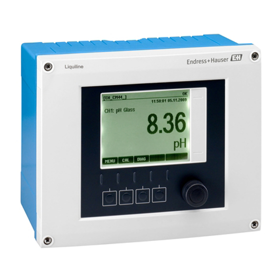
Display (red background in the event of an error) Navigator (jog/shuttle and press/hold function) Soft keys (function depends on the menu) 6.1.2 Display Menu path and/or device designation Status display Help if available a0012697-en Fig. 37: Display (example) Assignment of the soft keys Endress+Hauser... -
Page 28: Operation Concept
Fig. 40: Pressing the navigator: launching a function Fig. 41: Turning the navigator: selecting a value (e.g. from a list) a0012794-en a0012795-en Fig. 42: Pressing the navigator: accepting the new value Fig. 43: Result: new setting is accepted Endress+Hauser... -
Page 29: Configuration Options
• You know that the item in question is an action if it is preceded by the following symbol: • Examples of typical actions include: – Deleting log entries – Saving or loading configurations – Triggering cleaning programs • Example: Diagnostics/Logbooks/Configuration logbook/Delete all entries Endress+Hauser... - Page 30 – Cancel your entries without saving the data ( – Delete the character in front of the cursor ( – Move the cursor back one position ( – Finish your entries and save ( • Example: Menu/Setup/General settings/Device tag Endress+Hauser...
- Page 31 • You can add rows to the table (soft key "INSERT") or delete them (soft key "DEL"). • Afterwards, you save the table (soft key "SAVE"). • You can also cancel your entries any time via the soft key • Example: Menu/Setup/Inputs/pH/Medium comp. Endress+Hauser...
-
Page 32: Commissioning
Meas. screen 1 You can create 6 measuring screens of your own and give them a descriptive name. Meas. screen 6 As the functions are the same for all 6 measuring screens, only one measuring screen is described below. Endress+Hauser... -
Page 33: Basic Setup
For quick commissioning, you can ignore the additional settings for outputs, relays etc. You can make these settings later in the specific menus (see table below). Return to the measuring mode by pressing and holding the soft key for "ESC" for at least one second. Endress+Hauser... -
Page 34: Display
The current primary and secondary value, as well as all the raw values, are shown on the display. User-defined measuring screens You configure what values you want to display. You can choose from all the measured values of physical and "virtual" sensors (calculated using mathematical functions) and output parameters. Endress+Hauser... - Page 35 Main value, Raw value, Temperature Ammonium, Ammonium Ammonium, temperature Main value, Raw value, Temperature ion-sensitive Nitrate, Nitrate Nitrate, temperature Main value, Raw value, Temperature ion-sensitive Potassium, Potassium Potassium, temperature Main value, Raw value, Temperature ion-sensitive Interface UIS, turbidity measurement also: graphic display Endress+Hauser...
- Page 36 "Assignment views", e.g. Channel assignment view, appear as the last function in many sections of the menu. You can use this function to see what actuators or functions are connected to a sensor channel. The assignments appear in hierarchical order. Endress+Hauser...
-
Page 37: Technical Data
• In the measuring range 4 to 20 mA: Error current from 2.4 to 23 mA • Factory setting of the error current for both measuring ranges: 21.5 mA 8.2.3 Load Max. 500 Ω 8.2.4 Linearization/transmission behavior Linear, bilinear, table Endress+Hauser... -
Page 38: Current Output, Active
Min. 700,000 switching cycles – Max. 2 A at 24 V DC, L/R = 0 to 1 ms Min. 150,000 switching cycles – Max. 0.1 A at 24 V DC, L/R = 0 to 1 ms Min. 500,000 switching cycles Endress+Hauser... -
Page 39: Wiring
8.5.3 Cable entry Identification of the cable entry on the base of the housing Suitable gland B, C, H, I, 1-8 M16x1.5 mm / NPT3/8" / G3/8 A, D, F, G M20x1.5 mm / NPT1/2" / G1/2 RJ45 socket M12x1.5 mm Endress+Hauser... -
Page 40: Performance Characteristics
5x20 mm, 250 V, 4.0 A, slow-blow (T4.0A) Performance characteristics 8.6.1 Response time Current outputs = max. 500 ms for an increase from 0 to 20 mA 8.6.2 Reference temperature 25 ˚C (77 ˚F) 8.6.3 Measured error, inputs --> Documentation of the connected sensor Endress+Hauser... -
Page 41: Environment
8.7.5 Electrical safety IEC 61010-1, protection class I Low voltage: Overvoltage category II Environment < 3000 m (< 9840 ft) above MSL 8.7.6 Relative humidity 10 to 95%, not condensing 8.7.7 Pollution degree The product is suitable for pollution degree 4. Endress+Hauser... -
Page 42: Mechanical Construction
Display cover PC-FR Display film and soft keys Housing seal EPDM Module side panels PC-FR Module covers PBT GF30 FR Cable mounting rail PBT GF30 FR, stainless steel 1.4301 (AISI304) Clamps Stainless steel 1.4301 (AISI304) Screws Stainless steel 1.4301 (AISI304) Endress+Hauser... -
Page 43: Index
Span....... . 38 Open ....... . 9 Endress+Hauser... - Page 44 Icons Opening the housing ..... 18 Warnings ......5 Operation Identification .
- Page 45 Weight ....... . 42 Wiring ....... . 18 Endress+Hauser...
- Page 47 Declaration of Hazardous Material and De-Contamination Please reference the Return Authorization Number (RA#), obtained from Endress+Hauser, on all paperwork and RA No. mark the RA# clearly on the outside of the box. If this procedure is not followed, it may result in the refusal of the package at our facility.
- Page 48 BA444C/07/EN/13.10...
Need help?
Do you have a question about the Liquiline CM442 and is the answer not in the manual?
Questions and answers