Mitsubishi MELSEC-F FX3U-4AD-TC-ADP User Manual
Hide thumbs
Also See for MELSEC-F FX3U-4AD-TC-ADP:
- User manual (6 pages) ,
- User manual (3 pages) ,
- User manual (242 pages)
Table of Contents
Advertisement
Quick Links
JY997D14801F
Side
B
Side
Side
A
B
JAPANESE
ENGLISH
FX
-4AD-TC-ADP
3U
USER'S MANUAL
Manual Number
JY997D14801
Revision
F
Date
September 2008
This manual describes the part names, dimensions, mounting, and
specifications of the product. Before use, read this manual and the manuals of
all relevant products fully to acquire proficiency in handling and operating the
product. Make sure to learn all the product information, safety information, and
precautions.
Store this manual in a safe place so that it can be taken out and read whenever
necessary. Always forward it to the end user.
Registration:
The company and product names described in this manual are registered
trademarks or the trademarks of their respective companies.
Effective September 2008
Specifications are subject to change without notice.
©
2005 Mitsubishi Electric Corporation
Safety Precaution
(Read these precautions before use.)
This manual classifies the safety precautions into two categories:
and
.
Indicates that incorrect handling may cause hazardous
conditions, resulting in death or severe injury.
Indicates that incorrect handling may cause hazardous
conditions, resulting in medium or slight personal injury
or physical damage.
Depending on the circumstances, procedures indicated by
also cause severe injury.
It is important to follow all precautions for personal safety.
Associated Manuals
Manual name
Manual No.
Description
FX
3 G
/F X
3 U
/ FX
3 U C
Describes specifications for
Series
JY997D16701
analog control and
User's Manual
MODEL CODE:
programming method for FX
- Analog Control
09R619
FX
/FX
Series PLC.
3U
3UC
Edition
FX
/F X
/ FX
3 G
3 U
3 U C
Series
JY997D16601
Describes PLC programming
Programming Manual
MODEL CODE:
for basic/applied instructions
- B a s i c & A p p l i e d
09R517
and devices.
Instruction Edition
FX
Series
JY997D31301
3G
Ex plains FX
3G
Series PLC
User's Manual
MODEL CODE:
specifications for I/O, wiring,
installation, and maintenance.
- Hardware Edition
09R521
FX
3U
Series
JY997D16501
E xpla ins FX
Series PLC
3U
User's Manual
MODEL CODE:
specifications for I/O, wiring,
installation, and maintenance.
- Hardware Edition
09R516
FX
Series
JY997D28701
3UC
Explains FX
Series PLC
3UC
User's Manual
MODEL CODE:
specifications for I/O, wiring,
- Hardware Edition
09R519
installation, and maintenance.
How to obtain manuals
For product manuals or documents, consult with the Mitsubishi Electric dealer
from who you purchased your product.
Applicable standards
FX
3U
-4AD-TC-ADP
units made in June, 2005 or later comply with the EC Directive
(EMC Directive) and UL standards (UL, cUL). Further information can be found in the
following manual.
→ Refer to the FX
Series Hardware Manual (Manual No. JY997D33401)
3G
→ Refer to the FX
Series Hardware Manual (Manual No. JY997D18801)
3U
→ Refer to the FX
(D, DSS) Series Hardware Manual (Manual No.
3UC
→ Refer to the FX
-32MT-LT-2 Hardware Manual (Manual No. JY997D31601)
3UC
Regarding the standards that relate to the main unit, please refer to either the FX
series product catalog or consult with your nearest Mitsubishi product provider.
Caution for EC Directive
The analog special adapters have been found to be compliant to the European
standards in the aforesaid manual and directive. However, for the very best per-
formance from what are in fact delicate measuring and controlled output device
Mitsubishi Electric would like to make the following points;
As analog devices are sensitive by nature, their use should be considered care-
fully. For users of pr-oprietary cables (integral with sensors or actuators), these
users should follow those manufacturers installation requirements.
Mitsubishi Electric recommend that shielded cables should be used. If NO other
EMC protection is provided, then users may experience temporary loss or
accuracy between ±10% in very heavy industrial areas.
However, Mitsubishi Electric suggest that if adequate EMC precautions are fol-
lowed for the users complete control system, users should expect accuracy as
specified in this manual.
• Sensitive analog cable should not be laid in the same trunking or cable
conduit as high voltage cabling. Where possible users should run analog
cables separately.
• Good cable shielding should be used. When terminating the shield at Earth
- ensure that no earth loops are accidentally created.
• When reading analog values, EMC accuracy can be improved out by
averaging the readings. This can be achieved either through functions on the
analog special adapters or through a users program in the FX
PLC main unit.
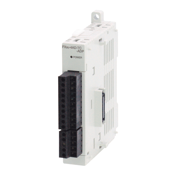
1. Outline
FX
-4AD-TC-ADP (hereinafter called TC-ADP) is an analog special adapter for
3U
measuring temperature via four channels of connected Type K or Type J thermocouple
thermometer.
1.1 Incorporated Items
Verify that the following product and items are included in the package:
Product
Manual
may
This
manual
1.2 External Dimensions, Part Names, and Terminal Layout
[5]
[3]
[4]
3G
/
[6]
[2]
[7]
[8]
[1]
7(0.28")
74(2.92")
15.5
15.1
(0.62")
(0.6")
17.6
[11]
(0.7")
Special adapter
connector cover
is removed
Weight: Approx. 0.1 kg (0.22 lbs)
[1] DIN rail mounting groove (DIN rail: DIN46277)
[2] Name plate
[3] Special adapter slide lock:
Used to connect additional special adapters onto the left side of this special
adapter.
[4] Special adapters connector cover:
Remove this cover to connect additional special adapters to the left side.
[5] Direct mounting hole:2 holes of φ4.5 (0.18") (mounting screw: M4 screw)
Not used when connecting to FX
3UC
JY997D28601)
[6] POWER LED (green):
Lit while 24V DC power is supplied properly to terminals '24+' and '24-'.
[7] Terminal block (European type):
Connect thermocouple sensor input, Type K or J changeover input, and 24V DC
power supply.
[8] Special adapter connector:
Used to connect this special adapter to PLC main unit or special adapter.
[9] DIN rail mounting hook
[10] Special adapter fixing hook
[11] Special adapter connector:
Used to connect communication or analog special adapters to the left side of the
TC-ADP.
2. Installation
For installation/uninstallation details, refer to the following manuals:
→ Refer to the FX
3G
→ Refer to the FX
3U
→ Refer to the FX
3UC
INSTALLATION
PRECAUTIONS
• Make sure to cut off all phases of the power supply externally before attempting
installation or wiring work.
Failure to do so may cause electric shock or damage to the product.
3U(C)
Series
INSTALLATION
PRECAUTIONS
• Use the product within the generic environment specifications described in PLC
main unit manual (Hardware Edition).
Never use the product in areas with excessive dust, oily smoke, conductive dusts,
corrosive gas (salt air, Cl
, H
S, SO
2
2
impacts, or expose it to high temperature, condensation, or rain and wind.
If the product is used in such conditions, electric shock, fire, malfunctions,
deterioration or damage may occur.
• When drilling screw holes or wiring, make sure cutting or wire debris does not
enter the ventilation slits.
Failure to do so may cause fire, equipment failures or malfunctions.
• Do not touch the conductive parts of the product directly.
Doing so may cause device failures or malfunctions.
• Connect special adapter securely to their designated connectors.
Loose connections may cause malfunctions.
2.1 Connection to the FX
Series PLC
3U
[10]
Procedure
24+
1) Turn off the power.
24-
Disconnect all the cables connected to the PLC main unit and special adapter, and
demount the main unit and special adapter mounted on DIN rail or mounted directly
using screws.
2) Install an expansion board to the main unit.
For the expansion board installation procedure, refer to the following manual:
J-type
→ Refer to the FX
3U
J-type
3) Remove the special adapter connector cover on
L1+
the expansion board (fig.A).
When connecting this product to another special
L1-
adapter, please replace the 'expansion board' in
L2+
the above description with a 'special adapter' and
L2-
perform the procedure as indicated.
L3+
4) Slide the special adapter slide lock
(fig.B) of the main unit.
L3-
When connecting this product to another special
L4+
adapter, please replace the 'main unit' in the
[9]
L4-
above description with a 'special adapter' and
perform the procedure as indicated.
5) Connect the
special adapter
(fig.C) to the
main unit as
shown on the
right
.
6) Slide back the
Series PLC.
special adapter
slide lock (fig.B)
of the main unit
to fix the special
adapter (fig.C).
Connection precautions
Connect all the high-speed I/O special adapters before connecting other
special adapters when they are used in combination.
Do not connect a high-speed I/O special adapter on the left side of a
communication or analog special adapter.
2.2 Connection to the FX
Series User's Manual - Hardware Edition.
Procedure
Series User's Manual - Hardware Edition.
1) Turn off the power.
Series User's Manual - Hardware Edition.
Disconnect all the cables connected to the PLC, and demount the PLC from
the DIN rail.
2) Remove the special adapter connector
cover (fig.A).
3) Slide the special adapter slide lock (fig.B)
of the main unit.
When connecting this product to another
special adapter, please replace the 'main
unit' in the above description with a 'special
adapter' and perform the procedure as
indicated.
, or NO
), flammable gas, vibration or
2
2
4) Connect the
special
adapter (fig.C)
to the main
unit as shown
on the right.
5) Slide back the
special
adapter slide
lock (fig.B) of
the main unit
to fix the
special
adapter (fig.C).
2.3 Connection to the FX
→ For details, refer to the FX
Series User's Manual - Hardware Edition
4)
B
3)
4)
A
B
B
C
6)
5)
6)
5)
5)
B
(D, DSS) Series PLC
3UC
3)
4)
2)
B
3)
A
B
B
C
5)
4)
5)
4)
4)
B
-32MT-LT(-2) Series PLC
3UC
Series User's Manual - Hardware Edition.
3UC
Advertisement
Table of Contents

Subscribe to Our Youtube Channel
Related Manuals for Mitsubishi MELSEC-F FX3U-4AD-TC-ADP


Summary of Contents for Mitsubishi MELSEC-F FX3U-4AD-TC-ADP
- Page 1 Before use, read this manual and the manuals of Do not connect a high-speed I/O special adapter on the left side of a Mitsubishi Electric recommend that shielded cables should be used. If NO other TC-ADP.
- Page 2 3kΩ main unit Mitsubishi will not be held liable for damage caused by factors found not to be • Make sure to properly wire to the European terminal board in accordance the cause of Mitsubishi; opportunity loss or lost profits caused by faults in the with the following precautions.
- Page 3 3kΩ main unit Mitsubishi will not be held liable for damage caused by factors found not to be • Make sure to properly wire to the European terminal board in accordance the cause of Mitsubishi; opportunity loss or lost profits caused by faults in the with the following precautions.
Need help?
Do you have a question about the MELSEC-F FX3U-4AD-TC-ADP and is the answer not in the manual?
Questions and answers