Table of Contents
Advertisement
Available languages
Available languages
Quick Links
826000480
Rev. A
ENG
Ed 06/2022
Datasensing S.r.l.
Strada S. Caterina 235 - 41122 Modena - Italy
Tel. +39 059 420411 - Fax +39 059 253973
web: www.datasensing.com
email: info@datasensing.com
S3N SERIES
IO-LINK® MODELS
Safety Precautions
Read the precautions for all models at http://www.datasensing.com.
WARNING: This product is not designed or rated to ensure personal safety either
directly or indirectly. Do not us it for such purposes.
WARNING: Do not exceed the rated voltage. There is a possibility of failure and
fire.
CAUTION: Do not use this product above its IP protection ratings. Failing to do so
may damage its components.
CAUTION: DC models shall never be used with AC mains power supply. Failing to
do so may result in explosions or other damage.
CAUTION: Use of controls or adjustments or performance of procedures other than
those specified herein may result in hazardous radiation exposure.
LASER
ATTENTION: L'utilisation de commandes ou d'ajustaments ou l'exécution de procéd-
1
ures autres que celles spécifiées ici peut entraîner une exposition à des rayonne-
ments dangereux.
CAUTION: Do not disassemble this product. Doing so may cause exposure to the
built-in light source which can damage eyes and skin. Never disassemble it.
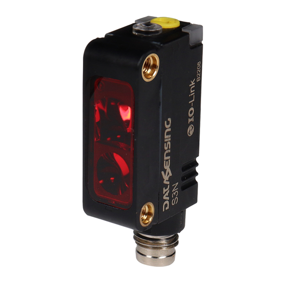
DESCRIPTION
The Photoelectric sensors of the S3N series are characterized by
compact dimensions, rugged package, excellent performance and
a wide range of models.
The range of optic functions of IO-Link models includes: diffused
proximity (standard and narrow beam), polarized retroreflex (LED
and Laser versions), Barrier (LED and Laser), Background suppres-
sion (LED and Laser) and Coaxial retroreflex for transparent objects
(LED).
All IO-Link models feature status, stability and IO-Link activity indi-
cators. Adjustment is made with a single teach pushbutton that is
used to configure the output function, or select the function mode
and adjust the sensitivity accordingly.
GENERAL CONTROLS
Teach Button
Performs all User interface interactions.
Output LED
The yellow LED indicates the output status and supports user inter-
face interactions during teach procedures.
Power On LED (All Models)
The green LED indicates that the sensor is operating.
IO-Link Activity LED
The Blue light is on during IO-Link data exchange.
DIMENSIONS
NOTE: "A" and "B" values in the following drawing are indicated in the "Optical Interaxes" table.
3,4
M3 X2
11.6
Version
S3N-PR-5-B03-OZ
S3N-PH-5-B03-OZ
S3N-PR-5-C03-OZ
S3N-PR-5-C13-OZ
S3N-PR-5-M03-OZ
S3N-PH-5-M03-OZ
S3N-PR-5-FG03-OZ (Emitter)
S3N-PH-5-FG03-OZ (Emitter)
S3N-PX-5-FG03-OZ (Receiver)
CONNECTIONS
G03 MODELS
ALL OTHER MODELS
BROWN 1
+10...30VDC
BLACK
4
C/Q
BLUE
3
0V
WHITE
2
N.C
10.8
Receiver
Emitter
M8x1
Optical Interaxes
A
8.25
6.2
6.3
7
10.2
10.2
---
---
7
M8 CONNECTOR
2
BROWN 1
+10...30VDC
BLACK
4
C/Q
1
BLUE
3
0V
WHITE
2
NPN/PNP OUT
INSTALLATION
The sensor can be positioned by means of the two threaded holes
(M3) using two screws (M3x12 or longer, or M2.5 pass through
screws + nuts) and relative washers. Maximum tightening torque is
0.5Nm.
Various brackets are available to ease the sensor positioning (please
refer also to accesories listed in the catalogue).
95ACC0024
A special bracket is available to ease mechanical setup of S3N-PR-
5-M03-OZ when used in "conveyor mode". The bracket helps setting
up the optimal angle between the sensor and the conveyor.
B
7.2
7.2
7.2
7.2
7.2
Snap Fit Mounting slits: for S3N-PR-5-FG03-OZ, special slits to be moun-
ted on the emitter (-G03) are available to narrow the aperture of the beam.
7.2
13.6
13.8
7.2
1x19
2x19
4
3
Mounting Bracket (various options)
Mounting screws
M3X12 or longer (screwing)
M2.5x12 or longer (passing)
95ACC0025
95ACC0026
95ACC0033 M03 fixing bracket
95ACC0024 S3N L-shaped bracket
M3X8
CLICK!
CLICK!
Ø 0.5
Ø 2
Ø 1
0.5x19
Advertisement
Table of Contents

Related Manuals for Datasensing S3N Series


Summary of Contents for Datasensing S3N Series
- Page 1 11.6 built-in light source which can damage eyes and skin. Never disassemble it. 95ACC0024 S3N L-shaped bracket DESCRIPTION Optical Interaxes The Photoelectric sensors of the S3N series are characterized by Version compact dimensions, rugged package, excellent performance and S3N-PR-5-B03-OZ 8.25 a wide range of models.
- Page 2 TEACH MODE SETTINGS available (see Teach Mode Functions table): form Teach 1. The sensor is set up to detect the target in the taught Teach1 (Standard Teach): The sensor is set up to exploit the maxi- position. Depending on the model, one or more Teach modes, tailored to mum allowable signal reserve.
-
Page 3: Io-Link Parameters
Weight: 10 g any means, or for any purpose, without the express written permission of Datasensing S.r.l. • Datasensing and the Datasensing logo are trademarks of Datasensing S.r.l. -
Page 4: Installation
Muttern) mit den entsprechenden Unterlegscheiben befestigt werden. Das maximale Anzugsdrehmoment beträgt 0,5Nm. 10.8 Datasensing S.r.l. Zur einfacheren Positionierung des Sensors sind verschiedene Strada S. Caterina 235 - 41122 Modena - Italien Montagewinkel verfügbar (auch Bezug auf das im Katalog aufgeführte Tel. - Page 5 ANLERNMODUS EINSTELLUNGEN wird dieses Verfahren durchgeführt: Die Winkel suchen, in denen S3N-PR-5-M03-OZ die gelbe LED (OUT) in beiden Richtungen (vertikal und horizontal) Je nach Modell verfügt der Sensor über einen oder mehrere ein- und ausschaltet, und den Sender in der Mitte zwischen diesen Anlernmodi, die für unterschiedliche Anwendungen ausgelegt sind S3N-PR-5-B03-OZ und S3N-PH-5-B03-OZ...
-
Page 6: Technische Daten
Tochtergesellschaften in irgendeiner Form oder mit einem beliebigen Gewicht: 10 g Mittel oder für einen beliebigen Zweck vervielfältigt, gespeichert oder in ein Datenabrufsystem eingegeben bzw. übertragen werden. • Datasensing und das Logo Datasensing logo sind eingetragene Marken von Datasensing S.r.l. - Page 7 (se référer également aux accessoires énumérés dans le Strada S. Caterina 235 - 41122 Modène - Italie catalogue). Tél. +39 059 420411 - Fax +39 059 253973 web: www.datasensing.com courriel : info@datasensing.com Équerre de fixation (différentes options) Mounting Bracket (various options) SÉRIE S3N Vis de montage...
- Page 8 MODES D’APPRENTISSAGE CONFIGURATIONS centre entre ces angles. Exécuter la procédure d'apprentissage parmi celles disponibles (voir le tableau des modes d'apprentissage désirée en la sélectionnant parmi celles disponibles (voir le tableau et de leurs fonctions) : Selon le modèle, un ou plusieurs modes d'apprentissage sont dis- des modes d'apprentissage et de leurs fonctions) : Teach1 (apprentissage standard BGS sur cible) : Positionner le ponibles sur le détecteur, conçus pour permettre différentes appli-...
-
Page 9: Données Techniques
11 ms (30 G) 6 chocs pour chaque axe (EN60068-2-27) Sélection CLAIR/SOMBRE : Via touche Teach ou configuration IO-Link La liste des brevets est consultable sur le site www.patents.datasensing.com. Sortie PNP/NPN : Configurable via configuration IO-Link Ce produit est protégé par un ou plusieurs brevets parmi les suivants : Brevets d'utilité... -
Page 10: Installazione
La coppia di serraggio massima è 0,5Nm. Sono disponibili diverse staffe per facilitare il posizionamento del 10.8 Datasensing S.r.l. sensore (fare riferimento anche agli accessori elencati nel catalogo). Strada S. Caterina 235 - 41122 Modena - Italia Tel. - Page 11 MODALITÀ DI APPRENDIMENTO IMPOSTAZIONI gli angoli in cui il LED giallo (OUT) si accende e si spegne in entrambe le direzioni (verticale e orizzontale), quindi fissare l'emettitore al In base al modello, sul sensore sono disponibili una o più modalità di centro tra questi angoli.
-
Page 12: Dati Tecnici
Peso: 10 g qualsiasi forma o con qualsiasi mezzo, o per qualsiasi scopo, senza l’espresso consenso scritto di Datasensing S.r.l. • Datasensing e il logo Datasensing logo sono marchi registrati di Datasensing S.r.l. - Page 13 Strada S. Caterina 235 - 41122 Modena - Italy 电话 +39 059 420411 - 传真 +39 059 253973 Mounting Bracket (various options) 安装支架(多种选项) 网站:www.datasensing.com 电子邮箱:info@datasensing.com S3N SERIES 安装螺钉 Mounting screws M3 X2 M3X12 or longer (screwing) M3X12 或更长(拧紧) IO-LINK® 型号...
- Page 14 示教模式 设置 传感器对准时使用此程序。 后执行示教 4 程序。设置传感器以使其能够可靠地检测传送 示教 3(切换亮/暗行为):传感器行为在亮暗开启模式之间 带上运行的物体。可使用特殊托架来简化此应用的机械设置。 根据不同的型号,传感器可采用一个或多个示教模式,适用于 切换。 示教 5(切换亮/暗行为):传感器行为在亮暗开启模式之间 各种不同的应用(参见“设置”段落)。 S3N-PR-5-B03-OZ 和 S3N-PH-5-B03-OZ 通过 IO-Link 设置:上述示教程序也可通过 IO-Link 启动。 切换。 按下“示教 (T)”按钮并观察绿色 LED 的行为,以执行所需示 此外,还可以通过改变灵敏度参数对灵敏度进行精细调节。 通过 IO-Link 设置:上述示教程序也 教模式的选择和传感器的调节;每当 LED 切换时,则意味着已 将传感器和反射镜在所需检测范围内相对放置,然后执行所需 为了增强环境光抗扰度,也可以通过 IO-Link 参数选择发射 可通过 IO-Link 启动。此外,还可以通过改变灵敏度参数对灵 选择新的示教模式。...
- Page 15 可通过 IO link 配置进行配置 该产品受以下一项或多项专利保护: 外壳: 主体:玻璃填充技术聚合物 实用专利:IT102015000057325,IT102017000151097, 指示灯: TPE 执行器:POM US10823878,US11146425,US11163090。 镜头: PMMA 防护等级: IP67 ©2022 Datasensing S.r.l. 连接: M8 连接器 4 极 • 保留所有权利 • 在不限制版权所有权,或未经 Datasensing S.r.l.书面许可的情况下,不得对此文档的任何一部分进行复 制、存储或将其引入检索系统,不得以任何形式、通过任何方法 重量: 10 g 对此文档进行传播,不得将此文档用于任何目的。• Datasensing 和 Datasensing 标识是 Datasensing S.r.l 的商标。...
Need help?
Do you have a question about the S3N Series and is the answer not in the manual?
Questions and answers