
Related Manuals for Hitachi ECO COMPACT PC-ARC-E


Summary of Contents for Hitachi ECO COMPACT PC-ARC-E
- Page 1 – INSTALLATION & OPERATION MANUAL – ECO COMPACT WIRED REMOTE CONTROLLER MODELS PC-ARC-E PMEN0630 rev.0 - 07/2022...
- Page 3 Hitachi’s control; Hitachi cannot be held responsible for these errors. Las especificaciones de este manual están sujetas a cambios sin previo aviso a fin de que Hitachi pueda ofrecer las últimas innovaciones a sus clientes.
- Page 4 Vi på Hitachi gör allt vi kan för att se till att alla specifikationer stämmer, men vi har ingen kontroll över tryckfel och kan därför inte hållas ansvariga för den typen av fel.
- Page 5 állnak a Hitachi ellenőrzése alatt; ezekért a hibákért a Hitachi nem tehető felelőssé. Zamieszczone w niniejszej instrukcji obsługi dane techniczne mogą ulec zmianie bez uprzedniego powiadomienia ze względu na innowacyjne rozwiązania, jakie firma Hitachi nieustannie wprowadza z myślą o swoich klientach.
- Page 6 Hitachi se bo trudil zagotoviti, da bodo vse specifikacije pravilne, medtem ko so tiskarske napake izven njihovega nadzora; Hitachi ni odgovoren za te napake. Špecifikácie uvedené v tejto príručke sa môžu zmeniť bez predchádzajúceho upozornenia, pretože spoločnosť Hitachi chce svojim zákazníkom prinášať najnovšie inovácie.
- Page 7 English Original Version Español Versión traducida Deutsch Übersetzte Version Français Version traduite Italiano Versione tradotta Português Versão traduzidal Dansk Oversat version Nederlands Vertaalde versie Svenska Översatt version Ελληνικα Μεταφρασμένη έκδοση Български Преведена версия Čeština Přeložená verze Magyar Lefordított változat Tłumaczenie wersji Polski oryginalnej Română...
- Page 8 The English version is the original one; other languages are translated from English. Should any discrepancy occur between the English and the translated versions, the English version shall prevail. La versión en inglés es la original, y las versiones en otros idiomas son traducciones de la inglesa. En caso de discrepancias entre la versión inglesa y las versiones traducidas, prevalecerá...
- Page 9 Η αγγλική έκδοση είναι το πρωτότυπο και οι εκδόσεις σε άλλες γλώσσες μεταφράζονται από τα αγγλικά. Σε περίπτωση που διαπιστωθούν διαφορές μεταξύ της αγγλικής και της μεταφρασμένης έκδοσης, η αγγλική έκδοση είναι επικρατέστερη. Версията на английски език е оригиналната; версиите на останалите езици са в превод от английски...
- Page 10 Verzija na engleskom jeziku je prvobitna verzija, a verzije na ostalim jezicima su prevedene s engleskog. U slučaju neslaganja između verzije na engleskom jeziku i prevedenih verzija, verzija na engleskom jeziku ima prednost. Izvirna različica je v angleškem jeziku; drugi jeziki so prevedeni iz angleščine. V primeru razhajanj med angleško in prevedeno različico, prevlada angleška različica.
-
Page 12: Table Of Contents
General Index 1. Safety summary ........................2. Button Names and Functions ..................... 3. System Configuration ......................3.1 Indoor Unit Group Control ..................4 4. Specifications ........................4.1 Hardware Specification ....................5 4.2 Communication Specification ................... 5 5. Operation ..........................5.1 Operation Start/stop ....................6 5.2 Operation Mode ...................... - Page 13 7.3.1 Run Indicator Setting ..................19 7.3.2 Capacity Control Details Setting ..............20 7.3.3 GentleCool Comfort Details Setting ............. 21 7.3.4 Operation Sound Setting ................22 7.3.5 Set the “IR Receiver” ON/OFF ................ 22 7.4 Individual Louver Operation ..................22 7.4.1 Individual Louver Setting ................
- Page 14 8.3.1 Operation Lock/Unlock Setting ..............52 8.3.2 NFC Setting ......................53 8.4 Check Menu ......................... 55 9. In Alarm Condition ......................9.1 Power Failure ....................... 57 9.2 Electromagnetic Interference (EMI) ................ 57 10. Checking Functions ......................10.1 List of Installation Functions ..................58 10.1.1 Indoor Unit Address Change ...............
-
Page 15: Safety Summary
If poured, it will cause a serious electrical shock. • DO NOT perform installation work and electrical wiring connection by yourself. Contact your Hitachi distributor or dealer and ask them for installation work and electrical wiring by service person. - Page 16 • Children should be supervised to ensure that they do not play with the appliance. • Important: read and understand this manual before using this remote controller. If you have any questions, contact your Hitachi distributor or dealer. PMEN0630 rev.0 - 07/2022...
-
Page 17: Button Names And Functions
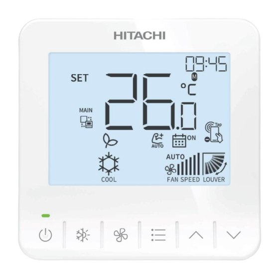
Button Names and Functions The figure below shows all the indications for reference. The actual display during operation is different. Current Time Temperature Set Indicator Louver Direction Mode Indicator Fan Speed Indi- cator Run Indicator On/Off Button Directional Key Operation Mode Button Menu Button Fan Speed Button... -
Page 18: System Configuration
System Configuration 3.1 Indoor Unit Group Control For indoor unit group control, one PC-ARC-E can control up to 16 indoor units. Up to 2 PC-ARC-E can be connected to the same indoor unit group. Up to 16 IDU Connection ..Simultaneous control for up to 16 IDU with transition wiring H-Link II Remote Control Cable... -
Page 19: Specifications
Specifications 4.1 Hardware Specification Item Specification Power supply Powered by indoor unit, 15VDC ± 10% W 90mm × H 90mm × D15.5mm (thinnest part) Dimensions W 90mm × H 90mm × D18.5mm (thickest part) Weight 100g (Approx.) Installation Method Installed on the wall or switch box Installation Condition Indoor 0-40 °C... -
Page 20: Operation
Operation 5.1 Operation Start/stop Press “ ” (run/stop). The run indicator will be turned on/off and the operation will be started or stopped accordingly. Operation Start Operation Stop NOTE • When heating operation stops, indoor unit(s) may keep running in Fan mode for about 2 minutes. -
Page 21: Operation Mode
5.2 Operation Mode Operation mode setting 1 Home screen is displayed. 2 Press “ ” to select “Mode”. The operation mode is switched in the following order: The operation mode can be limited by some optional function settings or by the "Operation Lock/Unlock Setting". -
Page 22: Fan Speed
3 Cooling, Dry, Fan operation: a minimum of 19°C. 4 Heating operation: a minimum of 17°C. NOTE • Depending on the type and setting of the indoor unit, it may not be possible to set the temperature by 0.5°C. In such case, the default temperature step is 1°C. •... -
Page 23: Swing Louver Direction
5.5 Swing Louver Direction 1 Press “ ” (On/Off). Make sure that the power is ON. 1 Press “ ” and select “Louver Direction”. 2 By pressing “ ” or “ ”, the louver direction changes as below diagram, and the direction of different types of louver is displayed differently. -
Page 24: Icon Description
Icon Description The status of the remote controller is displayed on the home screen. NOTE • Some of the status icons below may not be displayed depending on the type of outdoor unit or indoor unit you are using. Icon Description It is time to clean the air filter. - Page 25 Icon Description “AutoBoost” mode is ON. “On Timer” is set in the operation schedule. “Off Timer” is set in the operation schedule. NFC mode is ON. NFC mode is OFF. NOTE • (*1): The default setting is cooling: set temperature +2.5°C, heating: set temperature -2.5°C. If you want to change the correction value for this setback operation, please refer to the "Optional setting items for function selection".
-
Page 26: Advanced Functions Settings
Advanced Functions Settings NOTE • If some functions are not supported on the indoor unit, the relevant setting will be skipped automatically. • If schedule timer is not set, “Operation Schedule Setting” screen is not available, please refer to the Operation Schedule Details Setting. 7.1 Clock Setting This function is to set the date and time. - Page 27 “Month” Setting Set Value (Month) “Day” Setting Set Value (Day) “Hour” Setting Set Value (Hour) PMEN0630 rev.0 - 07/2022...
-
Page 28: Function Menu
“Minute” Setting Set Value (Minute) 3 After “Minute” is set, press “ ” to return to the home screen. 4 To end the operation during the setup, press “ ” to return to the home screen. 7.2 Function Menu 7.2.1 Access to the function menu 1 Each time the "Menu"... - Page 29 NOTE Icons are displayed alternatively, starting by the Louver icon or the Weekly Timer , depending ➀ ➁ on the indoor unit model and the available functions for this unit. Use the "Menu" button “ ” to navigate through the available options. Home Screen Louver Direction Press...
-
Page 30: Louver Setting
2 Press to modify the value of the selected function. “ ” or “ ” NOTE Some functions can be activated from this menu, whereas their detailled settings shall be done from the "Detailed Menu Operation". 7.2.2 Louver setting NOTE Refer to chapter 5.5 for details. -
Page 31: Comfort Setting
Icon Set Value ✓ The timer can be set from 0.5 to 23 hours. ✓ Press to increase or decrease 30 minutes of each step for 0.5 to 9.5 hours, 1 hour “ ” or “ ” of each step for 10 to 23 hours. 3 Press “... -
Page 32: Power Saving Setting
3 Press “ ” to save the setting and return to the home screen. When “GentleCool Comfort” mode is ON, “ ” is displayed on the home screen. The “ ” icon switches as “GentleCool Comfort Level” changes. Capacity Control Level Icon High NOTE... -
Page 33: Detailed Menu Operation
3 Press “ ” to save the setting and return to the home screen. 4 Refer to the detailed function menu to set the level of power saving if necessary. 7.3 Detailed Menu Operation 1 From home screen and IU "OFF", press “ ” for 3 seconds to display the detailed menu screen. 2 Press to switch the item number: “... -
Page 34: Capacity Control Details Setting
Set Value Set Value Description Run Indicator is deactivated Run Indicator is activated (default Item No. setting) 3 Press “ ” to save the setting. Once done, the item number starts flashing again. 4 Press “ ” (On/Off) once, or press “ ” for 3 seconds to return to the home screen. NOTE This process is only valid when the item number is blinking. -
Page 35: Gentlecool Comfort Details Setting
When “Capacity Control” mode is ON, “ ” is displayed on the home screen. The “ ” icon switches as “Capacity Control Level” changes. Capacity Control Level Icon High 7.3.3 GentleCool Comfort Details Setting This function is used to set “GentleCool Comfort Level”. NOTE •... -
Page 36: Operation Sound Setting
7.3.4 Operation Sound Setting This function is used to set the operation sound ON/OFF. 1 Enter “Operation Sound Setting” by selecting “05” as the item number. to switch the set value between “00 ↔01” to set the ”Operation Sound” ON/ 2 Press “... -
Page 37: Individual Louver Setting
• It cannot be set while the air conditioner is stopped. • The fan speed changes to “LOW” while this function is being set. After the setting is completed, the unit operation is back to normal. • As for “Start-up of Heating Operation”, “During Defrost Operation” and “Activation of Thermo- Controller”, all the louver angles are automatically secured horizontally when this function is activated. -
Page 38: Cancel Individual Louver Setting
Individual louver setting screen is displayed. 5 Press “ ” to select the individual louver. 6 Press “ ” to select the louver angle. Individual Louver Louver Angle 7 Press “ ” to save the setting and return to the home screen. The louver angle is changed as follows. -
Page 39: Set The Sleep Mode On/Off
(*3). For Heat Mode, the lower limit of the setting temperature is 20°C. NOTES • If clock has not been set, the On/Off setting will be skipped automatically. • “Off Timer” is set at 8 hours as default. It can be changed from “Sleep Mode Details Setting”, refer to “Detailed Menu Operation. -
Page 40: Sleep Mode Details Setting
7.5.2 Sleep Mode Details Setting This function is used to set “Off Timer” in the sleep mode. NOTE • The default value of “Off Timer” is 8 hours. • Refer to “Set the sleep mode ON/OFF”. 1 Enter “Sleep Mode Details Setting” by selecting “04” as the item number. 2 Press to increase or decrease 30 minutes of each step for 3.0 to 8.0 hours. -
Page 41: Set The Autoboost
7.6.1 Set the autoboost 1 Select “AutoBoost Setting”, refer to “Menu Operation”. 2 Press to switch AutoBoost mode between ON and OFF. “ ” or “ ” Icon Set Value (ON: , OFF: 3 Press “ ” to save the setting and return to the home screen. When the AutoBoost mode is ON, “... -
Page 42: Operation Schedule Details Setting
3 Press “ ” to save the setting and return to the home screen. 4 When the “Operation Schedule” is ON, “ ”, “ ”, or “ ” can be displayed on the home screen based on the timer setting in scheduled operation. -
Page 43: Ir Receiver Setting
✓ When both “On Timer” and “Off Timer” are not set, the wired remote controller returns to the home screen. 6 Press “ ” to select the day(s) into the schedule or press “ ” to remove the day(s) from the schedule. -
Page 44: Filter Reminder Reset Setting
NOTE • The IR receiver function can only be used on the home screen. • The wired remote controller does not support “Differentiate Indoor Units Set Close Together” at the wireless remote controller. • The wired remote controller does not support “Test Run” at the wireless remote controller. •... -
Page 45: Service & Installation Menu
Service & Installation Menu 8.1 Test Run 1 Press “ ” and “ ” simultaneously for 3 seconds to display the test run screen of Operation Stop state. 2 Press “ ” to switch mode and press “ ” to switch fan speed. Connected Indoor Unit No. -
Page 46: Function Selection
8.2 Function Selection 1 Press “ ” for 3 seconds to display the function selection setting screen. ✓ If only one indoor unit is connected with the wired remote controller, step4 is displayed. ✓ If multiple indoor units are connected with the wired remote controller, step2 is displayed. 2 Indoor unit selecting screen is displayed. - Page 47 5 Press to switch the set value. “ ” or “ ” Set Value (Flashing) 6 Press “ ” to confirm the set value, the screen returns to Step4. 7 Press “ ” in step4 or step5 to return to home screen. ◆...
- Page 48 Individual Element Optional function Settings Setting conditions Description setting Standard Locking of temperature setting on remote controller Fixed Usual setting Setting operation mode as cooling Unit Locked Function disabled Automatic COOL/HEAT operation Function enabled Standard Locking of fan speed setting on controller Locked Not available (Use as 00 setting Not available...
- Page 49 Individual Element Optional function Settings Setting conditions Description setting Standard static pressure / Standard speed Static pressure selection / High static pressure / Hi speed 1 (*5) Increase of Fan Hi speed Low static pressure / Hi speed 2 Function disabled Increase of fan speed at heating Thermo-OFF Function enabled...
- Page 50 Individual Element Optional function Settings Setting conditions Description setting Function disabled Power supply ON/OFF - option 2 Function enabled Dedicated Normal PID Fan Control optional Fan Control (Only for RPI- function applied (4.0-6.0)FSRE) (*6) to RPI units in combination Zoning system specific fan control with Airzone.
- Page 51 Individual Element Optional function Settings Setting conditions Description setting Function disabled (factory setting) Indoor unit fan control during cooling Thermo- OFF conditions Slow Forced Thermo-ON Function disabled (factory setting) when stopping in cooling Enabled operation Not used – Function disabled (factory setting) Control in “Automatic”...
- Page 52 Individual Element Optional function Settings Setting conditions Description setting 19°C 20°C 21°C 22°C 23°C Automatic reset 24°C temperature for cooling 25°C (*8) 26°C 27°C 28°C 29°C 30°C 17°C 18°C 19°C 20°C 21°C 22°C Automatic reset 23°C temperature for heating 24°C (*9) 25°C 26°C...
- Page 53 Individual Element Optional function Settings Setting conditions Description setting 19°C (factory setting) +1°C (Lower limit 20°C) +2°C (Lower limit 21°C) +3°C (Lower limit 22°C) +4°C (Lower limit 23°C) Lower limit of setting temperature for cooling +5°C (Lower limit 24°C) (*8) +6°C (Lower limit 25°C) +7°C (Lower limit 26°C) +8°C (Lower limit 27°C)
- Page 54 Individual Element Optional function Settings Setting conditions Description setting Not available (Use as 00 setting Not used conditions) Green Colour of the run indicator Not used Not used – Not used Not used Function disabled (factory setting) Eco-operation (*10) Function enabled Not used –...
- Page 55 Individual Element Optional function Settings Setting conditions Description setting 30°C (factory setting) -1°C (Upper limit 29°C) -2°C (Upper limit 28°C) -3°C (Upper limit 27°C) -4°C (Upper limit 26°C) Upper limit for cooling – -5°C (Upper limit 25°C) temperature setting -6°C (Upper limit 24°C) -7°C (Upper limit 23°C) -8°C (Upper limit 22°C) -9°C (Upper limit 21°C)
- Page 56 Individual Element Optional function Settings Setting conditions Description setting Not used – Not used – Not used – Not used – Not used – Not used – Operation of the louvers Direct air blow Low (factory setting) in energy-saving Thermo- Direct air blow Medium OFF (Cooling / Dry mode) Direct air blow High...
- Page 57 Individual Element Optional function Settings Setting conditions Description setting °C Temperature Unit °C/°F Selection °F Inlet air thermistor (Tin) Outdoor air thermistor (Tout) Temperature sensor displayed (*12) Remote controller sensor (RCS) Remote temperature sensor (THM4) Function disabled Display of sensor temperature (*13) Function enabled Display of setting...
- Page 58 Individual Element Optional function Settings Setting conditions Description setting Not used Not used Not used Not used Not used Not used Not used Not used Not used Not used Not used Not used Not used PMEN0630 rev.0 - 07/2022...
- Page 59 Individual Element Optional function Settings Setting conditions Description setting 0.5°C (1 °F) 1.0°C (2 °F) 1.5°C (3 °F) 2.0°C (3 °F) 2.5°C (4 °F) Setback Temperature 3.0°C (5 °F) Compensation 3.5°C (6 °F) 4.0°C (7 °F) 4.5°C (8 °F) 5.0°C (9 °F) 5.5°C (10 °F) Not used Not used...
- Page 60 In this case, duty (output Vsp for fan control) is fixed and it is not recalculated in basis of the target rpm as always does. This new feature also avoids the starting PID calculation, means that when a particular fan speed is demanded (e.g. High speed) from zoning system control to Hitachi control, the fan PMEN0630 rev.0 - 07/2022...
-
Page 61: Input / Output Setting
speed is automatically fixed without any possible oscillation. • When the unit is restarted by the controller, the temperature automatically changes to the setting temperature of “F5” or “F6”. • Applicable to the fan, cooling and dry operation modes. • Applicable to the heating operation mode. - Page 62 Indoor Unit No. (refrigerant system) Address No. of the selected unit Index No. 3 Press to select the indoor unit by changing the “Index No”. Then press “ ” to “ ” or “ ” confirm the selection. ✓ If all the indoor units are selected, the Index No. is indicated as FF. Index No.
- Page 63 5 Press to change the set values, and press “ ” to save the setting and return to “ ” or “ ” step4. Set Value (Flashing) 6 Press “ ” in step4 or step5 to return to home screen. ◆...
- Page 64 Code Indicated Output Not set Operation Alarm Cooling Thermo-ON for Cooling Heating Thermo-ON for Heating Total Heat Exchanger Elevate Grille Input Fan Operation Not set 10-15 NOTE • Change the optional setting after waiting at least three minutes elapsed time after start-up. •...
-
Page 65: Main Remote Setting
8.2.2 Main Remote Setting If multiple remote control groups exist in the same outdoor system, main/sub setting is automatically allocated. Set the desired Wired Remote Controller as the “Main” remote controller. Using this function, a sub remote controller can be set as main. ◆... -
Page 66: Service Menu
◆ Changing from the sub controller to the main controller 1 Press “ ” and “ ” simultaneously for 3 seconds to start changing from the sub controller to the main controller. The changed screen is displayed. Flash to Indicate Changing Process 2 When the change is completed, it returns to the home screen. -
Page 67: Nfc Setting
NOTE • Don’t use the operation lock function when remote control is set to “prohibit” on the central controller. • If both the “prohibit lock” and “prohibit remote control” operations are set at the same time, the “prohibit remote control” operation has priority. •... - Page 68 2 Press “ ” or “ ” to enable / disable NFC. NFC OFF/ON state code is indicated on the screen. State Code State Description NFC mode is disabled NFC mode is enabled 3 Press “ ” to complete the setting and return to the home screen. NOTE •...
-
Page 69: Check Menu
✓ If all data received from the App cannot be written to the controller, NFC alarm screen is displayed. Alarm Code Alarm Description An anomaly has occurred in the operation of NFC. NFC function is not supported. Other issue. ✓ Under NFC alarm state, press “ ” to confirm the warning and it returns to NFC function screen. - Page 70 1 Press “ ” and “ ” simultaneously for 3 seconds to display the check screen. Check Icon 01: Check 1 02: Check 2 2 Press to select “Check 1” or “Check 2” and press “ ” to turn to next step. “...
-
Page 71: In Alarm Condition
In Alarm Condition Indoor unit No. (Refrigerant system) Alarm Icon Indoor unit No. (Address No.) Alarm Code • The RUN indicator on the wired remote controller turns from green to red. • Alarm icon is displayed and keeps flashing. • The indoor unit number and alarm code are displayed on the screen. •... -
Page 72: Checking Functions
Checking Functions 10.1 List of Installation Functions Item Description Test Run To perform a test run of the outdoor unit and indoor unit. Function Selection To set Function Selection for the outdoor unit, indoor unit, and wired remote controller. Input/Output To assign signals to the external input/output ports of the indoor unit. - Page 73 2 Indoor unit selecting screen is displayed. Indoor Unit No. (refrigerant system) Address No. of the selected unit Index No. ✓ If there is only one indoor unit connected to the wired remote controller, this screen is not displayed. (The screen in step4 is shown.) ✓...
- Page 74 ✓ "P5" indicates that the address changing process is completed and successful. Successful change process ✓ "FL" indicates that the address changing process is abnormal and failed. Failed change process 8 When need to continue multiple indoor units address changing or to end the operation, press “...
-
Page 75: Setting Initialization
10.1.2 Setting Initialization This function is used to restore the factory default settings of Function Selection and Input/ Output. NOTE • The history display on the "Function Selection" screen is also updated to the factory default setting. • If the indoor unit that does not support Setting Initialization is selected, the factory default settings of Function Selection and Input/Output is not available. -
Page 76: List Of Check Functions
3 Indoor unit selecting screen is displayed if one indoor unit is connected. Indoor Unit No. (refrigerant system) Address No. of the selected unit Index No. 4 Press “ ” or “ ” to select the indoor unit by changing the "Index No.". Then press “ ” to confirm the selection. -
Page 77: Check 1 / Check 2
10.2.1 Check 1 / Check 2 1 Press “ ” and “ ” simultaneously for 3 seconds to display the check screen. Check Icon 01: Check 1 02: Check 2 2 Press to select “Check 1” or “Check 2” and press “ ” to turn to next step. “... - Page 78 ◆ Checking the current operating condition Contents of Check 1 Press “ ” to go to the next page. Press“ ” to go to the previous page. Temperature Status Display When Dual Setpoint is set, the setting temperature for Set Temp. auto mode is indicated.
- Page 79 Continue from previous page Stopping Cause State Indication Stopping Cause Refer to “Cause of Indoor Unit Stoppage” State Indication Continue to next page ◆ Cause of Indoor Unit Stoppage Code Cause Operation OFF, Power OFF Thermo-OFF Alarm (*1) Freeze Protection, Overheating Protection Instantaneous Power Failure at Outdoor Unit/Reset (*2) Instantaneous Power Failure at Indoor Unit/Reset (*3) Stoppage of Cooling Operation due to Low Outdoor Air Temp.
- Page 80 Code Cause Enforced Thermo-OFF due to Enforced Cleaning Operation Stoppage of Thermo-OFF by Motion Sensor Retry due to Abnormal Refrigeration Cycle Retry after Defrosting Operation Enforced Stoppage of Room Temperature Water (Heating) Switching to Refrigerant Operation under Air Conditioning Hot Water Supply System Enforced Thermo-OFF Stoppage of Target Indoor Unit due to Rotation Control at Indoor Unit (Outdoor ->...
- Page 81 Continue from previous page Abnormality counter Times of Abnormality Times of Power Failure Times of Abnormal This number is incremented when transmission error occurs Transmiting (Remote between Wired Remote Controller and Indoor units and the controller - Outdoor unit) error remains for 3 minutes or longer. Times of Inverter The maximum count is 99.
- Page 82 Indoor unit capacity code Code Indoor unit capacity number Equivalent horse power Code Indoor unit capacity number Equivalent horse power 200 • 224 7.5 • 8.0 10.0 Continue from previous page Abnormality counter IDU Electronic Expansion Valve (%) ODU Electronic Expansion Valve1 (%) ODU Electronic For flexible multi-type, the value of Unit A is indicated.
- Page 83 Continue from previous page R32 Refrigerant Leak Sensor Display R32 Refrigerant Leak Sensor 10 11 For example: 10 years and 11 months Sensor ON Integration Time: (Year.Month) R32 Refrigerant Leak Sensor 0 00 Unit is (×0.01V) Reference Voltage R32 Refrigerant Leak Sensor 0 00 Unit is (×0.01V) Output Voltage...
- Page 84 ◆ The data just before the latest failure Contents of Check 2 Press “ ” to go to the next page. Press“ ” to go to the previous page. Temperature Status Display Inlet Air Corresponds to item "b2" in Check 1. Temperature EconoFresh displays the temperature of direct-acting expansion valve coil.
-
Page 85: Alarm History Display
10.2.2 Alarm History Display Alarm history can be browsed and deleted. 1 Press “ ” for 3 seconds to display alarm history. 2 Press to switch "Alarm History Display" screen. “ ” or “ ” Indoor unit address Alarm history Alarm Code ✓... - Page 86 LCD check The No. in area Ⓐ is 02. 1 Press “ ” to turn on all icons. 2 Press “ ” to go to next check. No. in area Ⓐ Backlight check The No. in area Ⓐ is 03. 1 Press “...
- Page 87 Touch key and buzzer check The No. in area Ⓐ is 05. 1 Press each key once a time in the sequence as follows: " " " " " " " " 2 The No. in area Ⓑ increases by 1 with each switch pressing. No.
- Page 88 Thermistor check The No. in area Ⓐ is 07. 1 The temperature on the remote controller thermistor is shown in area Ⓑ. 2 Press “ ” to go to next check. Temperature showed in area Ⓑ No. in area Ⓐ NOTE The thermistor temperature is the same as ambient temperature and the tolerance is ±1°C.
- Page 89 IR check The No. in area Ⓐ is 09. No. in area Ⓐ ✓ Not check IR Press “ ” or “ ” simultaneously for 3 seconds and the screen turns to next check directly. ✓ Check IR If the signal of the wireless remote controller is detected, the screen moves to next check automatically.
- Page 90 EEPROM check The No. in area Ⓐ is 11. Error indicated in area Ⓑ No. in area Ⓐ ✓ Not clear EEPROM Press “ ” or “ ” simultaneously for 3 seconds and the screen turns to home screen. ✓ Check EEPROM Press “...
-
Page 91: Reset Wired Remote Controller
10.2.4 Reset Wired Remote Controller To delete the settings of Wired Remote Controller or re-connect the controller to the unit, follow the below steps to reset the controller. NOTE It is not possible to delete only part of the record data by resetting. 1 Press “... - Page 92 PMEN0630 rev.0 - 07/2022...
-
Page 93: Precautions
Precautions Wired Remote Controller can be connected to any indoor unit that corresponds to H-LINK II. Wire with indoor units uses twisted pair cable. Ensure that the total length of the wire is shorter than 500m. PMEN0630 rev.0 - 07/2022... - Page 96 Johnson Controls-Hitachi Air Conditioning Spain, S.A.U. Ronda Shimizu, 1 - Políg. Ind. Can Torrella 08233 Vacarisses (Barcelona) Spain © Copyright 2022 Johnson Controls-Hitachi Air Conditioning Spain, S.A.U. – All rights reserved. PMEN0630 rev.0 - 07/2022 Printed in China...
Need help?
Do you have a question about the ECO COMPACT PC-ARC-E and is the answer not in the manual?
Questions and answers