
Related Manuals for Gardner Denver RBS 15


Summary of Contents for Gardner Denver RBS 15
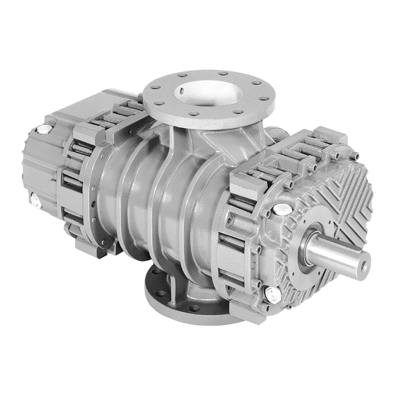
- Page 1 SERVICE MANUAL AND PARTS LIST BLOWERS Models RBS 15-225 RB-7-100 Version 01 09, 2016...
- Page 2 Blower MODEL and SERIAL NUMBER (see nameplate on unit). Rely upon the knowledge and experience of your AUTHORIZED DISTRIBUTOR and let them assist you in making the proper parts selection for your blower. To Contact Gardner Denver or locate your local distributor: Visit: www.contactgd.com/mobile Call: (217)222-5400...
- Page 3 GARDNER DENVER LUBRICANT ORDER INFORMATION Re-order Part Numbers for Factory Recommended Lubricants. Gear and Drive End AEON PD Synthetic Lubricant, AEON PD-XP—Extreme Duty Synthetic Lubricant or AEON PD-FG—Food Grade Synthetic Lubricant AEON PD Synthetic Lubricant Description Part Number 1 Quart...
- Page 4 FOREWORD blowers are the result of advanced engineering and skilled manufacturing. To be assured of receiving maximum service from this machine, the owner must exercise care in its operation and maintenance. This m a n u a l is written to give the operator and maintenance department essential information for day-to-day operation, maintenance and adjustment.
-
Page 5: Safety Precautions
SAFETY PRECAUTIONS Safety is everybody’s business and is based on your use of good common sense. All situations or circumstances cannot always be predicted and covered by established rules. Therefore, use your past experience, watch out for safety hazards and be cautious. -
Page 6: Drive Installation
NOTICE When changing mounting configuration, it may be necessary to reposition breather/oil fill (B), oil level gauge (H) and drain plug (A). Refer to Figure 3-1, for correct location. DRIVE INSTALLATION When selecting a V-belt drive, check to be sure the shaft overhung load limitation is not exceeded. - Page 7 ENGLISH INDEX 1 OPERATING PROBLEMS ..................2 REMOVAL OF THE BLOWER FROM THE PLANT ............. 2.1 Stopping the blower..................... 2.2 Disassembling the connections................2.2.1 Disassembling the piping ................. 2.2.2 Disassembling the silencers ................2.3 Removal of the blower from the unit ..............2.3.1 Direct coupling ....................
- Page 8 ENGLISH INDEX 6 INSTALLATION OF THE BLOWER ON THE PLANT ..........6.1 Assembling of the driving devices ..............6.1.1 Direct drive coupling ..................6.1.2 V-belt drive coupling ..................6.2 Coupling the blower ..................... 6.2.1 Direct drive coupling ..................6.2.2 V-belt drive coupling ..................6.3 Assembling of the piping .................
-
Page 9: Operating Problems
1 OPERATING PROBLEMS PROBLEM CAUSE High absorbed power 1-3-6-7-8-9-10-11-12-13-14 WARNING : STOP THE BLOWER IMMEDIATELY Differential pressure higher than the contract value 1-3-6-7-8 WARNING : STOP THE BLOWER IMMEDIATELY Discharge temperature T2 higher than the contract value 2-4-5-6-7-8 WARNING : STOP THE BLOWER IMMEDIATELY High vibrations and/or noises 9-10-11-12-13-14-15 WARNING : STOP THE BLOWER IMMEDIATELY... -
Page 10: Stopping The Blower
2 REMOVAL OF THE BLOWER FROM THE PLANT 2.1 Stopping the blower If the blower is still in operation remove, if possible, the differential pressure. Stop the electric supply WARNING: Check that the deceleration of the blower is even and without vibrations. Close the cooling water circuit (only for /RV) Insulate the blower from the plant and restore the atmospheric pressure into it. - Page 11 2.3 Removal of the blower from the unit Disassemble the drive protection device Unscrew the screws fixing the blower to the base frame 2.3.1 Direct drive coupling Lift the blower using hoisting devices suitable to his weight (table 7.1) Fig. 1 2.3.2 V-belt drive coupling Loosen the V-belts approaching the motor to the blower using the screws of the motor rails Thrust screws...
- Page 12 2.4 Disassembling of the drive devices 2.4.1 Direct drive coupling Loose the safety screw G fixing the key 30 Extract the coupling by means of a suitable device. WARNING: Do not use the hammer to extract the coupling. Screw G Key pos.
- Page 13 3 DISASSEMBLING OF THE BLOWER 3.1 Preparation Clean the external surface of the blower Drain the lubricating oil WARNING: Dispose the used oil in accordance with local regulations Drain the cooling liquid (only for the /R-V version) WARNING: Dispose the cooling liquid in accordance with local regulations. Mark the position of the covers 5A and 5B and the position of the drive shaft in order to use these marks during the following assembly of the blower.
- Page 14 3.2 Disassembling of the drive side Remove the drive sump 12A WARNING: Use the hoisting devices suitable to the weight of sump (table 7.1) 3.2.1 Sizes from 15 to 106 Extract the protection ring 37 by means of an extraction device as indicated in figure Unscrew the screw 27B and extract the locking disk 17 of the bearing 32 Bronze pad Screw 27B...
- Page 15 3.2.2 Sizes from 115 to 225 Unscrew the nut 27A and with it extract the shaft sleeve 37, if the operation is difficult extract the sleeve 37 by means of an extractor device as indicated at paragraph 3.2.1 Unscrew the screw or nut 27B and extract the disk 17 locking the bearing 32 extract the oil splash disk 24 For the sizes from 115 to 126 extract the cover 5A screwing alternatively four fixing screws into the suitable extraction holes as indicated in Fig.
- Page 16 3.3 Disassembling of the gear side Remove the gear sump 5B WARNING: Use the hoisting devices suitable to the weight of sump (table 7.1) WARNING : Secure the cover 5B fixing it to the casing 1 using two fixing screws pos. 90 with big diameter washer for sizes from 15 to 126 and the prefixing screws for sizes from 135 to 225 3.3.1 Disassembling the gear side, sizes from 15 to 25 Unscrew the locking nuts 26 and remove the washers 311...
- Page 17 3.3.2 Disassembling the gear side, sizes from 35 to 225 Unscrew slightly the locking nuts 26 and move them 1 or 2 mm away from the gear wheels WARNING: DO NOT REMOVE THE LOCKING NUTS 26, because by releasing the gear wheels they may be cast out.
- Page 18 3.3.3 Extraction of cover 5B, sizes from 15 to 25 Disassemble the bearing cover 35 Extract the rotors using an extractor fixed to the threaded holes of the casing as indicated in figure 13 Remove the safety screws fixing the cover 5B to the casing1 and extract it Bronze pad Safety screw Washer...
- Page 19 3.4 Final disassembly Mark the position of the rotors Extract the rotors from the casing 1 fixing them to the threaded holes on their drive side WARNING: For the lifting of the rotors do not use the threaded end on the gear side nor the threaded holes on the gear side WARNING: Use the hoisting devices suitable to the weight of the rotors (table 7.1) 3.4.1 Cover 5A...
- Page 20 4 REPAIR OF THE PARTS 4.1 Rotors Clean the external surface of the rotors, remove the incrustations and rust using solvents and scraper. WARNING: Keep to the prescribed safety rules when using solvents and wear protection glasses and safety gloves NOTE: Do not damage the external surface of the rotors when using the scraper Check the external surface of the rotors, if there are any signs of seizure, cracks or grooves replace the rotors.
- Page 21 4.2 Casing Clean the external surface of the internal, remove the incrustations and rust using solvents and scraper. WARNING: Keep to the prescribed safety rules when using solvents and wear protection glasses and safety gloves NOTE: Do not damage the internal surface of the rotors when using the scraper Check the internal surface of the casing, if there are any signs of seizure, cracks or grooves replace the casing.
- Page 22 Measure the dimension Width W in various points of the teeth of the two wheels using a comparator as indicated in figure 17, the number of teeth for the measure W is indicated in the table Measuring Teeth n° size teeth 15-25 35-45-46...
- Page 23 4.6 Labyrinth seals Clean the sealing spacers and the sealing chambers, remove the incrustations and rust using solvents and scraper. WARNING: Keep to the prescribed safety rules when using solvents and wear protection glasses and safety gloves NOTE: Do not damage the surface of the sealing spacers and the sealing chambers when using the scraper Extract the sealing piston rings from the sealing spacers Check the external surface of the spacers 25, if the surface has spots of rust replace the spacers...
- Page 24 5 ASSEMBLING OF THE BLOWER 5.1 Preparation Before the reassembly of the blower clean all the elements and oil the elements that are in contact with each other. Place the cover 5B on suitable wooden supports in order to have a free space below of almost 300 mm as indicated in figure 18 Place the casing 1 onto the cover 5B using suitable ropes passing around the nozzles as indicated in figure 18, with the threaded holes F of the flanges downwards, to position the casing use the reference pins of the...
- Page 25 5.2 Assembling of the drive side Place the cover 5A onto casing 1 using the reference pins and the marks carried out during the disassembly of the blower WARNING: Use the hoisting devices suitable to the weight of the cover (table 7.1). 5.2.1 Sizes from 15 to 25 Insert the oil splash disks 23 A onto the shaft by means of a pipe as indicated in figure 20.
- Page 26 5.2.2 Sizes from 35 to 106 Insert the sealing spacers Pos. 25 completed with the sealing piston rings as indicated in the paragraph 5.4. Insert the oil splash disks 23A and 23C onto the sealing spacers by means of a pipe as indicated in figure 22. Size 35-45-46 55-65-66...
- Page 27 5.2.3 Sizes from 115 to 155 Insert the sealing spacers 25 completed with the sealing piston rings as indicated at paragraph 5.4. Insert the oil splash disks 23A and 23C onto the sealing spacers by means of a pipe as indicated in figure 24 Size 115-125-126 135-145-155...
- Page 28 5.2.4 Sizes from 165 to 225 Insert the compensating spring Pos. 63 Insert the sealing spacers 25 completed with the sealing piston rings as indicated at paragraph 5.4. Insert the oil splash disks 23A and 23C onto the shaft Mount the bearings 31 and 32 as indicated at paragraph 5.5.1 and 5.5.2. Lock the bearing 31 with the nut 27A and relevant washer Insert the spacer 56 and the lubricating disk 16A onto the driven shaft Lock the assembly by means the nut 27 and relevant washer...
- Page 29 5.3 Assembling of the gear side WARNING: Fix the cover 5B to the casing 1 by means the safety screws For the sizes from 15 to 106 use two screws Pos. 90 with two washers of big diameter, for the sizes from 115 to 225 use the suitable holes in the cover as indicated in figure 27 Casing 1 Casing 1...
- Page 30 5.3.1 Sizes from 15 to 25 Remove the cover 5B Place four sheets LM with thickness alike the value of the maximum clearance indicated in the table 7.4 in the third column as indicated in figure 29 Fig. 29 Place the cover 5B Insert the oil splash disks 23B by means of a pipe as indicated in figure 30 Pipe Oil splash disk 23B...
- Page 31 5.3.2 Sizes from 35 to 126 Insert the sealing spacers 25B with the sealing piston rings as indicated at paragraph 5.4. Insert the oil splash disks 23B onto the sealing spacers by means of a pipe as indicated in figure 31. Pipe Size 35-45-46...
- Page 32 5.3.3 Sizes from 135 to 225 If at least one of the parts that generate the axial clearance between the rotors and the cover 5B: spacers Pos. 25, oil splash disks Pos. 23B (only sizes from 165 to 225), rotors and cover Pos. 5B has been replaced then prepare two adjusting rings Pos.
- Page 33 5.4 Assembling of the labyrinth seals Install the sealing spacers by means the mounting device and by a pipe as indicate in figure 35 Size Pipe 35-45-46 Sealing spacer 25 55-65-66 75-85-86 Mounting device 95-105-106 115-125-126 135-145-155 165-175 205-225 Fig. 35 The mounting device must have the dimensions indicated in the figure 36 below Size 35-45-46...
- Page 34 5.5 Assembling of the bearings Clean and oil the matching surfaces of the bearings, of the shafts and of the bearing housings WARNING: Use the hoisting devices suitable to the weight of the bearings (table 7.1). WARNING: Do not use the hammer to introduce the bearings 5.5.1 .1 Bearing Pos.
- Page 35 5.5.2 Bearing Pos. 32 Size 15-25 35-45-46 Threaded rod Thrust nut 55-65-66 75-85-86 95-105-106 115-125-126 Thrust disk Bearing 32 135-145-155 165-175 205-225 Fig. 39 WARNING: The device must be fixed to the end of driver shaft as indicated in 39 5.5.3 Bearings pos.
- Page 36 5.6 Assembly of the timing gear 5.6.1 .1 Preparation Arrange the rotors in the position indicated in the figure below Interpose between the rotors a metal sheet LL with thickness equal to maximum value of the clearance rotor/rotor indicated in the table 7.4 at the sixth column and long about the 70% of the length of the rotors Lock the rotors in this position by means of the wooden spacers SL with dimension higher than dimension L and fixed by means the plates P fixed to the casing nozzles as indicated in figure 41 Spacer DL...
- Page 37 5.6.2 Sizes from 15 to 25 Clean carefully the tapered ends of the shafts Clean carefully the surface of the tapered holes of the wheels Insert the toothed wheels onto the shaft and press them slightly by hand Insert the shims 22A in the original position using the marks made during the blower disassembly Measure the dimension QI indicated in figure for each toothed wheel, if the rotors or the wheels have not been replaced the dimension must be in the range indicated in the column L of the table 7.6.
- Page 38 5.6.3 Sizes from 35 to 225 Clean carefully the tapered ends of the shafts Clean carefully the surface of the tapered holes of the wheels Insert the spacers 22 and the shims in the same original position as indicated in figure 44 using the marks made during the blower disassembly Insert the toothed wheel 11 A onto the drive shaft and the toothed wheel 11B onto the driven shaft using the marks made during the blower disassembly...
- Page 39 Tightening procedure of the nuts 26 Screw the injector or the oil pump to the shaft end using eventually the suitable connecting screws, for the devices see table 7.5, for the connection screws see table 7.6. Inject oil and screw alternatively the nut 26 until the gear wheel has been tightened to the spacer 22. The tightening torque Ms of the nuts 26 is indicated in the table 7.6 WARNING: The oil pressure during assembly of the wheels may reach 2200 bar and the incorrect assembly of the injector or of the oil pump may cause serious physical injury owing...
-
Page 40: Final Checks
5.7 Final checks Place the blower onto a horizontal plate and carry out the following check: Tightening torque of the screws Pos. 90 fixing the covers and the oil sumps Tightening torque of the oil plugs Tightening torque of the oil levels ... - Page 41 6 INSTALLATION OF THE BLOWER SHEAVE AT THE PLANT 6.1 Assembling of the driving devices 6.1.1 Direct drive coupling Oil the blower shaft Insert the key 30 Slide the coupling onto the shaft using a suitable device as indicated in figure WARNING: Do not use the hammer to introduce the coupling Size 15-25...
-
Page 42: Alignment Check
6.2 Coupling of the blower 6.2.1 Direct drive coupling Place the blower at the distance S from the motor as indicated in the table below. Align the shafts of the blower and of the motor by shims under the feet of the motor and/or blower. Check the alignment by using comparators or gauges with scales as shown in Fig. - Page 43 6.2.2 V-belt drive coupling Fix the blower to the base frame by means the fixing screws Approach the electric motor by means of the suitable thrust screws Install the V-belts Produce belt tension by using the motor thrust screws in accordance with the values shown in the table Diameter D of smaller Deflection V-belt...
-
Page 44: Putting Into Operation
6.3 Assembling of the piping Install the suction and discharge silencers using suitable hoisting devices WARNING: The silencers with DN higher than 150 weight more than 50 kg. WARNING: The silencers do not induce loads and/or tension onto the blower nozzles Install the elastic connectors. -
Page 45: Technical Tables
7.1 TECHNICAL TABLES 7.1 Weight of the main components Blower Main components Blower Rotor Casing Cover Sump Gear Bearing [kg] [kg] [kg] [kg] [kg] [kg] [kg] Size 1040 1180 1790 1890 2870 3270... - Page 46 7.2 Bearings Bearings Blower Pos. 31 Pos. 32 Pos. 33 NJ 205 E 6304-C3 3205-C3 NJ 2208 6207-C3 3207-C3 NJ 310 E 6308-C3 3309-C3 NJ 312 E 6310-C3 3310-C3 NJ 314 E 6312-C3 3312-C3 22316 6314-C3 22314 22319 6317-C3 22317 23222 22319 22319...
-
Page 47: Tightening Torques
7.3 Tightening torques 7.3.1 Screws and nuts Tightening torque [Nm] Blower Screw Pos. 27A Pos. 27B Pos. 83 Pos. 84 Pos. 90 Pos. 92A Pos. 403 Pos. 407 15-25 35-45-46 55-65-66 75-85-86 95-105-106 115-125-126 135-145-155 165-175 205-225 7.3.2 Plugs and sight glasses Tightening torque [Nm] Blower... - Page 48 7.4 Clearances Rotor / Casing Gear Rotor Rotor Rotor / Rotor Blower Cover 5A Cover 5B Inlet side Outlet side Inlet side Outlet side 17-25 8-10 10-16 18-24 12-15 17-24 8-12 14-18 6-10 22-27 12-18 16-26 18-26 8-12 18-22 6-12 25-35 13-18 25-30...
- Page 49 7.6 References for gear tightening Wedging Tightening torque for the nut ring 26 Oil injection Blower connection Type of nut Tolerance [Nm] [mm] [mm] [Nm] 15-25 0,90 1,10 M 16 X 2 0 +10 35-45-46 3,40 3,50 GUP 30 X 1,5 0 +10 G 1/4 55-65-66...
-
Page 50: Section 8 Parts Lists
Section 8 Parts Lists 8.1 RBS 15-25 Sectional drawing, FIGURE 8-3... - Page 52 8.2 8.2 RBS 35-106 Sectional drawing, FIGURE 8-2...
- Page 55 8.2 RBS 115-225 Sectional drawing, FIGURE 8-3...
- Page 58 OVERHAUL KITS...
- Page 62 For additional information, contact your local representative or visit: www.contactgd.com/mobile ©2012 Gardner Denver, Inc. Printed in U.S.A.
Need help?
Do you have a question about the RBS 15 and is the answer not in the manual?
Questions and answers