
Related Manuals for Gardner Denver 4500 Series


Summary of Contents for Gardner Denver 4500 Series
- Page 1 PARTS LIST OPERATING AND SERVICE MANUAL 4500 SERIES BLOWERS “A” AND “C” SERIES 6” - 7” - 8” GEAR DIAMETER Models GDF_ _A_ - - 6” GDG_ _A_ - - 7” GDH_ _C_ - - 8” SB- -7- -626 Version 05...
- Page 2 Rely upon the knowledge and experience of your AUTHORIZED DISTRIBUTOR and let them assist you in making the proper parts selection for your blower. For the location of your local authorized Gardner Denver blower distributor refer to the yellow pages of your phone directory, check the Web site at www.gardnerdenver.com or contact:...
-
Page 3: Gardner Denver Lubricant Order Information
Part Number 1 Quart 28H97 Case/12 Quarts 28H98 5 Gallon Pail 28H99 55 Gallon Drum 28H100 Call your local Sutorbilt Distributor to place your order for Gardner Denver lubricants. Your Authorized Gardner Denver Distributor is: SB- -7- -626 Page ii... - Page 4 FOREWORD Sutorbilt blowers are the result of advanced engineering and skilled manufacturing. To be assured of receiving maxi- mum service from this machine the owner must exercise care in its operation and maintenance. This book is written to give the operator and maintenance department essential information for day-to-day operation, maintenance and adjustment.
- Page 5 SAFETY PRECAUTIONS Safety is everybody’s business and is based on your use of good common sense. All situations or circumstances cannot always be predicted and covered by established rules. Therefore, use your past experience, watch out for safety hazards and be cautious. Some general safety precautions are given below: Failure to observe these notices could result in injury to or death of personnel.
-
Page 6: Table Of Contents
TABLE OF CONTENTS Page Maintain Blower Reliability and Performance with Genuine Gardner Denver Parts and Support Services ..Instructions for Ordering Repair Parts .............. -
Page 7: Foreword
INDEX AEON PD Food Grade Lubricant Part Numbers Lubrication Instructions ......AEON PD Lubricant Part Numbers ... . . MAINTENANCE, SECTION 5 . - Page 8 LIST OF ILLUSTRATIONS Figure 1 Operating Principles ..............Figure 2 Lifting the Blower .
- Page 9 MATRIX/MENU 4500 SUTORBILT BLOWERS NOTICE TO CUSTOMER -- To find the construction options for your blower unit, FILL IN THE BALANCE OF LETTERS OR __ __ __ __ __ __ __ __ __ __ __ NUMBERS FROM YOUR UNIT NAMEPLATE COLUMN NUMBER: 9 10 11 FOLLOW THE LINE DOWN AND OVER FROM EACH SPACE...
-
Page 10: Introduction Your Key To Trouble Free Service
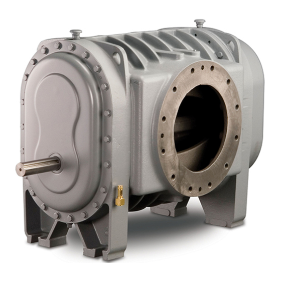
INTRODUCTION YOUR KEY TO TROUBLE FREE SERVICE Thank you for investing in Sutorbilt quality. The Sutor- OPERATING PRINCIPLES -- The 4500 Series rotary bilt reputation for rugged dependability has been blowers are the positive displacement type with two figure--eight shaped impellers rotating in opposite earned by over 50 years of service in demanding, directions inside the casing. -
Page 11: Section 1, Equipment Check
SECTION 1 EQUIPMENT CHECK Before uncrating, check the packing slip carefully to be To prevent rusting of gears, bearings, etc., the oil sure all the parts have been received. All accessories reservoirs may be filled with normal operating oil. are listed as separate items on the packing slip, and small important accessories such as relief valves can be overlooked or lost. -
Page 12: Section 2, Installation
SECTION 2 INSTALLATION LOCATION Install the blower in a well lit, clean, dry place with plenty of room for inspection and maintenance. FOUNDATIONS For permanent installations we recommend concrete foundations be provided, and the equipment should be grouted to the concrete. It is necessary that a suitable base be used, such as a steel combination base under blower and motor, or a separate sole plate under each. -
Page 13: Drive Installation
Eye bolts and lifting lugs are designed to support the The calculated shaft moment must not exceed the weight of the blower only. They are not intended to be maximum allowable moment listed in Maximum used to lift packages or components. See FIGURE 2, Allowable Moment Chart, FIGURE 4, page 5. -
Page 14: Figure 4 Belt Drive Overhung Load Limitations
Dimensions Maximum Gear (Inches) Allowable Diameter Moment (Inches) (LB--IN) (Max) 6.60 2.10 4123 7.88 3.00 4758 9.50 2.70 7488 MAXIMUM ALLOWABLE MOMENT DRIVE SHAFT ILLUSTRATION 0.000 1.000 0.250 0.966 0.500 0.926 0.750 0.879 1.000 0.823 1.250 0.751 0.025 0.997 0.275 0.962 0.525 0.922... -
Page 15: Section 3, Pre--Start
SECTION 3 PRE- -START AEON PD Lubricant Description Part Number 1 Quart 28G23 Case/12Quarts 28G24 5 Gallon Pail 28G25 55 Gallon Drum 28G28 AEON PD Food Grade Lubricant Description Part Number 1 Quart 28H97 Case/12Quarts 28H98 5 Gallon Pail 28H99 55 Gallon Drum 28H100 FIGURE 6 - - AEON PD SYNTHETIC LUBRICANT... -
Page 16: Figure 7 Lubrication Recommendation
To drain, remove drain plugs (D in FIGURE 5, page 6) listed in FIGURE 7. Do not use an oil that contains EP at the bottom. AEON PD Synthetic Lubricant should be additives. drained after 6000 hours of operation. Re--fill with fresh AEON PD oil. -
Page 17: Air Filters And Filter Silencers
Vertical Configuration Horizontal Configuration Gear Diameter Splash Lubrication Splash Lubrication (in) Drive End Gear End Total Drive End Gear End Total 1.5 pt. 1 qt. 1.75 qt. 2.5 pt. 5 pt. 3.75 pt. 1 qt. 5 pt. 3.5 qt. 5 pt. 7 pt. -
Page 18: Section 4, Operation
SECTION 4 OPERATION Future operating problems can be avoided if proper LIMITATIONS precautions are observed when the equipment is first put into service. For information regarding limitations, refer to “Maxi- mum Operating Limitations,” FIGURE 9, page 10. Before starting under power, the blower should be turned over by hand to make certain there is no binding, or internal contact. -
Page 19: Shut Down
Full rated pressure is full pressure Precaution should be taken to insure differential from the inlet flange to the that the unit cannot be started discharge flange. accidentally and cause injury to personnel or damage to equipment. SHUT DOWN If the unit is to be shut down for extended periods of The blower should be unloaded before shut down. -
Page 20: Blower Startup Checklist
BLOWER STARTUP CHECKLIST This startup procedure should be followed during the initial installation and after any shutdown periods or after the blower has been worked on or moved to a new location. It is suggested that the steps be followed in sequence and checked off ( ) in the boxes provided. -
Page 21: Safety Precautions
SAFETY PRECAUTIONS Do not operate blower with open inlet or outlet port. Do not exceed specified vacuum or pressure limitations. Do not exceed sheave or coupling Do not operate above or below recommended manufacturers’ rim speed limit. blower speed range. See FIGURE 9, page 10. Blower is not to be used where non--sparking equipment is specified. - Page 22 TROUBLE SHOOTING (Continued) PROBLEM POSSIBLE CAUSES SOLUTION Lack of volume. Slipping belts. Tighten belts. Worn clearances. Re-establish proper clearances. Excessive bearing Improper lubrication. Correct lubrication level. Replace or gear wear. dirty and/or improper oil. Headplate, gear case or Clean vents. Loss of oil.
-
Page 23: Section 5, Maintenance
SECTION 5 MAINTENANCE GEAR INSPECTION Inspection of the timing gears may be accomplished simply by removing the gear case. Refer to FIGURE 10. Remove the bolts from the gear case and detach it from the head plate. Timing gears and gear end bearings are now exposed. -
Page 24: Clearance, End
FIGURE 12 - - IMPELLER LOBE CLEARANCES clearance and c--c should have 1/3, maintaining mini- mallet. This will release the grip rings inside the gear mum open and closed per FIGURE 11, page 14. hub so that the impeller will be free to adjust. Do not remove the gear. -
Page 25: Section 6, Repair & Replacement
SECTION 6 REPAIR & REPLACEMENT FIGURE 13 - - TIMING GEAR ASSEMBLY FIGURE 14 - - TIMING GEAR REMOVAL With proper maintenance and lubrication, normal life of Reassembly bearings, gears and seals can be expected. To main- tain the efficiency of your unit, however, these parts To reassemble, locate each gear firmly against the must be repaired or replaced when required. -
Page 26: Bearing And Seal Replacement
BEARING O- - RING BEARING BEARING RETAINING CARTRIDGE RING * * Later models use (4) clips instead of solid ring. FIGURE 15 - - BEARING CARTRIDGE REMOVAL BEARING AND SEAL REPLACEMENT Gear End Remove the gear case (see “Gear Inspection,” page 14). -
Page 27: Drive End
changes, and lubricate the shaft surface. Item 45 must fit tight against the impeller end. Sleeve 46 is now installed on the shaft against item 45. The mechanical seal should be assembled into the bearing cartridge item 19 on the bench. First insert O--ring 47 into the groove. -
Page 28: Section 7, Parts List, Vertical Construction
SECTION 7 PARTS LIST VERTICAL CONSTRUCTION Order by Part Number and Description. Reference Numbers for your convenience only. 6” VERTICAL Reference Figure 17, Page 31, for Exploded View Size Size Size Size Ref. DESCRIPTION Req’d GDFA_A GDFB_A GDFC_A GDFD_A BEARING (DRIVE END) . - Page 29 6” VERTICAL (Continued) Size Size Size Size Ref. DESCRIPTION Req’d GDFA_A GDFB_A GDFC_A GDFD_A PIN- -DOWEL (HEADPLATE ... 62M50 62M50 62M50 62M50 TO IMPELLER CASE) WASHER- -PLAIN (BEARING ..95U3 95U3 95U3...
-
Page 30: 7" Vertical
Order by Part Number and Description. Reference Numbers for your convenience only. 7” VERTICAL Reference Figure 17, Page 31, for Exploded View Size Size Size Size Ref. DESCRIPTION Req’d GDGA_A GDGB_A GDGC_A GDGD_A BEARING (DRIVE END) ....910721070501 910721070501 910721070501... - Page 31 7” VERTICAL (Continued) Size Size Size Size Ref. DESCRIPTION Req’d GDGA_A GDGB_A GDGC_A GDGD_A LOCKWASHER (BEARING ... 95B3 95B3 95B3 95B3 CARTRIDGE TO HEADPLATE) SCREW- -HX HD CAP/NYLOK ..655EC03N 655EC03N 655EC03N...
-
Page 32: 8" Vertical
Order by Part Number and Description. Reference Numbers for your convenience only. 8” VERTICAL Reference Figure 17, Page 31, for Exploded View Size Size Size Size Ref. DESCRIPTION Req’d GDHA_C GDHB_C GDHC_C GDHD_C BEARING (DRIVE END) ....903639090110 903639090110 903639090110... - Page 33 8” VERTICAL (Continued) Size Size Size Size Ref. DESCRIPTION Req’d GDHA_C GDHB_C GDHC_C GDHD_C LOCKWASHER (BEARING ... . 95B3 95B3 95B3 95B3 CARTRIDGE TO HEADPLATE) SCREW- -HX HD CAP/NYLOK ..75A33N 75A33N 75A33N...
-
Page 34: Section 8, Parts List, Horizontal Construction
SECTION 8 PARTS LIST HORIZONTAL CONSTRUCTION Order by Part Number and Description. Reference Numbers for your convenience only. 6” HORIZONTAL Reference Figure 18, Page 32, for Exploded View Size Size Size Size Ref. DESCRIPTION Req’d GDFA_A GDFB_A GDFC_A GDFD_A BEARING (DRIVE END) . - Page 35 6” HORIZONTAL (Continued) Size Size Size Size Ref. DESCRIPTION Req’d GDFA_A GDFB_A GDFC_A GDFD_A PIN- -DOWEL (HEADPLATE ... . 62M50 62M50 62M50 62M50 TO IMPELLER CASE) WASHER- -PLAIN (BEARING ... 95U3 95U3 95U3...
-
Page 36: 7" Horizontal
Order by Part Number and Description. Reference Numbers for your convenience only. 7” HORIZONTAL Reference Figure 18, Page 32, for Exploded View Size Size Size Size Ref. DESCRIPTION Req’d GDGA_A GDGB_A GDGC_A GDGD_A BEARING (DRIVE END) ....910721070501 910721070501 910721070501... - Page 37 7” HORIZONTAL (Continued) Size Size Size Size Ref. DESCRIPTION Req’d GDGA_A GDGB_A GDGC_A GDGD_A SCREW- -SOC HD CAP (HEAD- - ..75P2 75P2 75P2 75P2 PLATE TO IMPELLER CASE) LOCKWASHER (BEARING ... . 95B3 95B3 95B3...
-
Page 38: 8" Horizontal
Order by Part Number and Description. Reference Numbers for your convenience only. 8” HORIZONTAL Reference Figure 18, Page 32, for Exploded View Size Size Size Size Ref. DESCRIPTION Req’d GDHA_C GDHB_C GDHC_C GDHD_C BEARING (DRIVE END) ....903639090110 903639090110 903639090110... - Page 39 8” HORIZONTAL (Continued) Size Size Size Size Ref. DESCRIPTION Req’d GDHA_C GDHB_C GDHC_C GDHD_C LOCKWASHER (BEARING ... . . 95B3 95B3 95B3 95B3 CARTRIDGE TO HEADPLATE) SCREW- -HX HD CAP/NYLOK .
-
Page 40: Section 9, Exploded Views
SECTION 9 EXPLODED VIEW SB- -7- -626 Page 31... -
Page 41: Figure 19 Exploded View -- Horizontal Construction
SB- -7- -626 Page 32... -
Page 42: Section 10, Service Replacement, 8" Unit Gear And/Or Rotor Replacement
SECTION 10 SERVICE REPLACEMENT 6” & 7” HORIZONTAL UNITS OIL LEVEL GAUGE REPLACEMENT 1986 TO PRESENT 1983 THRU 1985 ADAPTOR GAUGE 6” UNIT 7” UNIT PART NO. PART NO. ”A” 5.50 6.25 63C1 40P47 ”B” 4.69 5.00 64D1 40P48 NOTE: Units built prior to 1983 utilized a 3/4”... - Page 43 8” UNIT GEAR AND/OR ROTOR REPLACEMENT Size Size Size Size Design Version Description Req. GDHA GDHB GDHC GDHD GEAR REPLACEMENT KIT--CONVERSION 209GDH6005 209GDH6005 209GDH6005 209GDH6005 KIT--CONVERSION 210GDH6005 210GDH6005 210GDH6005 210GDH6005 ROTOR REPLACEMENT KIT--CONVERSION 200GDH6005 201GDH6005 202GDH6005 203GDH6005 KIT--CONVERSION (Gas Pump) 204GDH6005 205GDH6005 206GDH6005...
-
Page 44: Warranty
Company’s judgment is proved not to be as warranted. Gardner Denver (the “Company”) warrants to each orig- Labor shall be limited to the amount specified in the inal retail purchaser (“Purchaser”) of its products from Company’s labor rate schedule.
Need help?
Do you have a question about the 4500 Series and is the answer not in the manual?
Questions and answers