Table of Contents
Advertisement
Quick Links
Advertisement
Table of Contents

Related Manuals for EVBox Audi Wallbox

Summary of Contents for EVBox Audi Wallbox
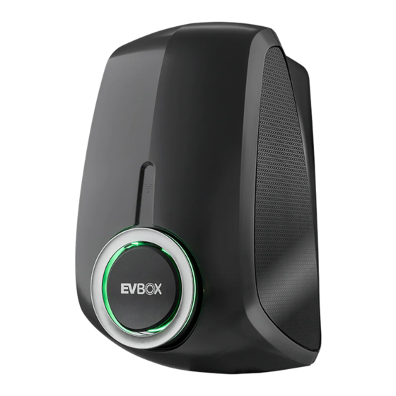
- Page 1 Audi Wallbox Installation and User Manual Powered by...
- Page 2 Manufacturer of this wallbox: EVBox Manufacturing B.V. Kabelweg 47 1014 BA, Amsterdam Netherlands Distribution of Audi Wallbox by Elli – A Brand of the Volkswagen Group Volkswagen Group Charging GmbH Mollstraße 1 10178 Berlin Germany...
- Page 3 English...
-
Page 4: Table Of Contents
Start and stop a charging session Maintenance Status indication Troubleshooting Configure Audi Wallbox plus and Audi Wallbox pro Configure the Audi Wallbox plus and Decommissioning Audi Wallbox pro locally Configuration Manager Pair Audi Wallbox plus and Disposal Audi Wallbox pro to app account... -
Page 5: General Information
General information Scope of the document Danger Retain all documentation delivered with the wallbox in a safe place for the entire life Not following the instructions given in this cycle of the product. Forward all documen- manual will result in the risk of electric tation to any subsequent owners or users of shock to users, which will cause severe the product. - Page 6 Software updates Make sure that the wallbox always has the latest software. Please note that a software update requires the approval via the myAudi app. Information about the latest software updates can be found at https://www.elli. eco/de/changelog/wallbox. The user is free to install or reject the update.
-
Page 7: Safety Precautions
Safety precautions Read and obey the following safety precautions before installing, servicing or using the wall- box. A certified electrician must ensure that the wallbox is installed in accordance with the relevant country-specific standards and local regulations. Symbols The symbols used in this manual have the following meaning: Symbols used and their explanations 1., a. - Page 8 The following sections contain general information that applies when using the wallbox. Danger Not following the instructions given in this › In the event of danger and/or an accident document will result in the risk of electric (e.g. formation or smell of smoke, cable shock to users, which will cause severe breaks, etc.) disconnect the electrical injuries or death.
- Page 9 Warning Improper usage of the wallbox could re- › Always check that the contact area of sult in damage to the wallbox, which could the charging plug is free from dirt and cause injury or death. moisture before starting a charging session.
- Page 10 Caution Notice Putting fingers into or leaving other Charging the electric vehicle with the objects inside the plug port could cause charging cable not being completely injury or damage to the wallbox. unwound may result in overheating of the cable, which could damage the wallbox. ›...
-
Page 11: Product Information
Product information The table below contains the available product configurations for the Audi Wallbox models. Audi Audi Wallbox Audi Wallbox Features Wallbox plus Maximum output power • • • 7.4 kW (1-phase) Maximum output power • • • 11 kW (3-phase) Attached charging cable •... - Page 12 1 - 6 mm². terminals: 1 - 10 mm². Metering (only applies MID-certified kWh meter to Audi Wallbox pro) Safety and certification Minimum dedicated 1-phase 32 A (32 A station) or 3-phase 16 A Upstream installation (16 A station) upstream circuit breaker and at minimum RCD type protection A (30 mA AC).
- Page 13 Normal Environmental Outdoor use. conditions Access Equipment for locations with non-restricted access. Connectivity (Only applies to Audi Wallbox plus and Audi Wallbox pro) Authorization RFID (ISO 14443, ISO 15693). Wi-Fi 2.4 / 5 GHz, only WPA2 (IEEE802.11 a - ax) Ethernet Via RJ45 connection, 10/100 Mbit/s / 100BASE TX (IEEE 802.3u)
-
Page 15: Charge With The Wallbox
Charge with the wallbox Warning Using a damaged wallbox (e.g. expanded housing, crack in the cable, etc.) may expose the user to electric components and could result in the risk of electric shock, which could cause injury or death. › Always check that the wallbox is free ›... -
Page 16: Start And Stop A Charging Session
Make sure that the plug does not touch the ground when stowed. * For Audi Wallbox plus and Audi Wallbox pro only. -
Page 17: Status Indication
Status indication LED description LED states Wallbox state Solid LED Vehicle state Flashing LED House state State remains unchanged RFID state * Green light is exemplary, blue, yellow and red lights are possible as well. Please refer to the colour in the states described below. - Page 18 State description Display Off or energy saving Wallbox is starting up. Wait until the wallbox is ready to charge.* Configuration Manager accessible via Wi-Fi hotspot. Be aware that charging is not possible during this state.* Idle - ready to charge. 1.
- Page 19 State description Display Vehicle connected, charging paused by app or charge card. The charging session will continue when allowed. Private charging. Vehicle connected, not charging, vehicle paused / fully charged. Vehicle connected, wai- ting for charge card input or remote authorization.* Vehicle connected, stop charging with charge card or remote authorization...
- Page 20 / app rejected.* Vehicle connected, charging. Software update in progress. If the wallbox shows other states than the ones described above, see chapter Trouble- shooting for more information. * For Audi Wallbox plus and Audi Wallbox pro only.
-
Page 21: Configure Audi Wallbox Plus And Audi Wallbox Pro
Audi Wallbox pro to the internet and into the local network is required. The compatible, EEBus-capable home energy management system (HEMS) must be on the same local network as the Audi Wallbox plus and Audi Wallbox pro. Functionalities depend on the HEMS used. -
Page 22: Configuration Manager
The local configuration of the Audi Wallbox is only possible for the connective versions of the wallbox, i.e. Audi Wallbox plus and Audi Wallbox pro. The Audi Wallbox is not equipped with a communication board and therefore, not capable to offer any connectivity functionality. - Page 23 Automatic identification of the individual Audi QR Code Walbox during pairing process in the myAudi app The Pairing Code and QR Code are for explicit identification of the individual Audi Wallbox within the myAudi app. This code is not needed to use the Configuration Manager...
- Page 24 The Configuration Manager can be acces- 1. Enable the Elli Charger’s Wi-Fi hotspot. sed using the Audi Wallbox's Network Host a. If the input power to the Audi Wallbox Name. Enter the hostname into the brow- is on, have it switched off at the power ser’s navigation bar, prepending “https://”...
- Page 25 Reference the local networks confi- Be aware of possible address conflicts on guration page to identify the Audi Wallbox's the local network if the Audi Wallbox is local network IP-Address. assigned to an already used IP-Address. The Audi Wallbox's local IP-Address will...
- Page 26 Optional, click on the button “TURN OFF LTE” 1. Make sure that the LTE interface is d. Wait for the Audi Wallbox to close exis- disabled. ting mobile network connections, this a. Click on the tab “LTE”.
- Page 27 Energy Management System management system is the right one. a. You will see a popup window that Before you connect your Audi Wallbox to the requests you to do a visual check of the energy management system. Please consider SKI-Number (Identification number) of the following framework conditions: the energy management system.
- Page 28 Select the Preferred Language 5. Remove energy management system. a. If you want to connect the Audi Wallbox 1. Navigate through the Configuration to another energy management system, Manager’s menu Language Settings. you must first unpair the previously 2. Select the favored language for the Con- paired one.
-
Page 29: Pair Audi Wallbox Plus And Audi Wallbox Pro To App Account
Pair Audi Wallbox plus and Audi Wallbox pro to myAudi app account To use all online services offered by the Audi Wallbox plus and Audi Wallbox pro, you must link your wallbox to your myAudi account. 1. Download the myAudi app for using the Audi charging services. -
Page 30: Prepare For Installation
Prepare for installation Danger Not following the instructions given in this document will result in the risk of electric shock to users, which will cause severe injuries or death. › The installation must only be performed by certified electricians, who can correctly and safely install the wallbox and identify potential danger. -
Page 31: Prerequisites For Installation
RS485 cable ** x 1 Wallbox plus with feed- Charge card * through terminals Fastening kit for main assembly x 1 * For Audi Wallbox plus and Audi Wallbox pro only. ** For Audi Wallbox pro only. Your Audi Wallbox pro Possible 1-phase 3-phase... - Page 32 Pre-installation checklist › The local installation regulations are identi- fied and are followed. › A miniature circuit breaker (MCB) and resi- dual current device (RCD) must be installed upstream and have ratings that correspond to the local power supply as well as to the required charging power.
-
Page 33: Tools And Material Needed
Tools and material needed A. Additional tools and material needed Torx screwdriver T30, with Drill minimum working length of 20 cm Pliers Screwdriver 5.5 mm Hammer Cable stripper Ethernet cable crimper Optional: CT Coil cable connector MCVR 1.5 / 3 - ST - 3.81 Drill bit 8 mm ›... - Page 34 M4 x 10 mm 2.3 - 2.7 Nm M6 x 16 mm 7.3 - 8.6 Nm M6 x 60 mm 8 - 11 Nm * For Audi Wallbox plus and Audi Wallbox pro only. ** For Audi Wallbox pro only.
-
Page 35: Notice On Installation
Notice on installation Warning Connecting the wallbox to the power supply other than as specified in this section could result in incompatibility of the installation as well as the risk of electric shock, which could cause damage to the wallbox, and injury or death. ›... - Page 36 Power supply wiring Option 1: 400 V 3-phase with neutral For 3-phase use of a Wye-connected secondary, all three phases (L1, L2 and L3) and neutral must be connected. Each phase voltage must measure 230 V to neutral. Option 2: 230 V 1-phase with neutral For 1-phase use of a Wye-connected secondary, only a single phase (L1 or L2 or L3) and neutral on the grid must be con- nected to the L1 and N on the terminal block of the wallbox.
-
Page 37: Install Wallbox
Install wallbox Danger Notice Not taking precautions against ESD Working on electric installations without (Electrostatic discharge) could damage proper precautions will result in the risk electronic components in the wallbox. of electric shock, which will cause severe injuries or death. ›... -
Page 38: Install Wall Bracket
Install wall bracket Place the wall bracket on the wall and use a 3. Mount the wall bracket on the wall using bubble level to align it. Make sure that the the three screws M6 x 60 mm and three UP arrow on the bracket points upwards. - Page 39 Warning Warning Leaving sharp edges after removing the Removing more knockouts and/or blind break-out tabs can cause damage to the plugs than necessary for cable routing and cables which could result in the risk of leaving open holes will affect the protecti- electric shock, which could cause severe on against moisture of the wallbox, which injury or death.
- Page 40 a. Remove the lock nuts from the cable c. Make sure the following lengths of cables glands and mount the cable glands on the are available after the cable glands, then power supply cable and (optionally) on the tighten each cable gland. CT coil cable and Ethernet cable with their ›...
-
Page 41: Mount Main Assembly Onto Wall Bracket
Mount main assembly Assemble wallbox onto wall bracket 1. Install power supply cable. 1. Engage the top edge of the main assem- bly with the top of the wall bracket and then rotate the main assembly so it is flat on the wall bracket. - Page 42 Connect the wires according to the Audi Wallbox model and the color coding table below. A. Audi Wallbox and Audi Wallbox plus without kWh meter: a. Connect L1 (and L2 and L3 - for 3-phase version) wire(s) of the power supply cable to L1, L2, L3 slots of the feed- through terminals.
- Page 43 B. Audi Wallbox pro with kWh meter c. Connect PE wire of the power supply a. Connect L1 (as well as L2 and L3 - for cable to the first available slot of the PE 3-phase version) wire(s) of the power...
- Page 44 2. Optionally, install and connect the CT 3. Install and connect charging cable. coil cable a. Strip the outer insulation of the cable Warning to a length of 50 mm, then strip the individual wires to 7 mm. An incorrect routing of the wires of the charging cables will result in improper ins- tallation, which could cause a malfunction of the ground (earth) leakage detection...
- Page 45 b. Connect the PE wire of the charging Color coding for the provided EV charging cable cable to the second available slot of the PE feed-through terminal. Wires Green / Color Brown Black Grey Blue Yellow 4. Set the DIP-switches. c.
- Page 46 6. Optionally, connect the RS485 cable. 7. Optionally, install and connect the Ether- net cable. a. Insert the three wires into the kWh meter following the color coding below. a. Strip the outer insulation of the cable, then strip and crimp the individual wi- res to a suitable length for the Ethernet Color coding for the provided RS485 cable connector.
- Page 47 RFID a. Connect the HMI cable to the HMI cable to the communication board. (for board. Audi Wallbox plus and Audi Wallbox pro only) e. Before closing the wallbox, check and b. Connect the RFID cable to the HMI ensure the following: board.
- Page 48 f. Place the front cover onto the main 10. Wind the charging cable around the assembly by using the provided hooks of wallbox for proper storage. the front cover. Mount the front cover by tightening the six screws M4 x 10 mm. 11.
-
Page 49: Adjust The Length Of The Charging Cable
Adjust the length of the charging cable 1. Loosen the two screws of the charging cable strain relief with a Torx 10 screwdriver. 2. Hold the cable and adjust the position of the charging cable holder by turning it counterc- lockwise. -
Page 50: Set Dip-Switches
› The installation must only be performed by certified electricians, who can correctly and safely install the wallbox and identify potential danger. The Overload Protection feature of the Audi Wallbox enables use of as much power of the installation as possible at any given time. For more information, see chapter Overload Protection. - Page 51 To be set by To be set by user.* user.* Nidec 3000:1 C-CT-10 Nidec 3000:1 C-CT-16 Nidec 3000:1 C-CT-24 3000:1 TT 50-SD 3000:1 TT 100-SD 2500:1 E4623-X002 2500:1 E4624-X002 2500:1 E4626-X002 * For Audi Wallbox plus and Audi Wallbox pro only.
- Page 52 DIP-switch 5, in group A configures the functio- See chapter Configure the Audi Wallbox nality of the ground loss monitor. By default, plus and Audi Wallbox pro locally for more this feature is enabled from the factory. information. Any different configuration than the...
- Page 53 Group B switches No CT coil attached CT coil DIP-switch number and Station Max Current Facility/ position house Max Illustration Current per 16 A 32 A phase 3-phase 1-phase 16 A 32 A 10 A 13 A 10 A 10 A 16 A 11 A 11 A...
- Page 54 Group B switches No CT coil attached CT coil DIP-switch number and Station Max Current Facility/ position house Max Illustration Current per 16 A 32 A phase 3-phase 1-phase 15 A 15 A 35 A invalid 16 A 40 A invalid 17 A 50 A...
- Page 55 Group B switches No CT coil attached CT coil DIP-switch number and Station Max Current Facility/ position house Max Illustration Current per 16 A 32 A phase 3-phase 1-phase invalid 25 A 160 A invalid 26 A 180 A invalid 27 A 200 A invalid...
-
Page 56: Overload Protection
This section introduces the Audi Wallbox's Overload Protection and provides guidance for installing the needed components. In addition, all technical parameters and restrictions of the Audi Wallbox's control system are listed for certified electricians to be able to decide on a proper installation design. - Page 57 Notice The Overload Protection is a comfort feature of the Audi Wallbox. It is not claiming to fulfil any country-specific standards or local requirements. The Overload Protection is neither a substitute for security devices, such as breakers, to protect electrical installations from damage due to excess currents.
- Page 58 In order to reduce EMC noise to a of the Audi Wallbox and the provided minimum, a double/foil-braid shielded cable gland. data cable with twisted wire pairs (S/FTP) c.
- Page 59 CT coil’s place of installa- tion. c. Optionally, in case of an Audi Wallbox plus or pro, use the Configuration Mana- ger to conduct further CT coil settings. d. Optionally, in case of an Audi Wallbox...
- Page 60 Technical parameters The list of CT coils that are supported by the Audi Wallbox by default can also be obtained from chapter Set DIP-switches (page 49). In addition to the CT coil models mentioned in chapter Set DIP-switches, the CT coil models that are possible to use as default with any variant of the Audi Wallbox are listed.
- Page 61 Hereafter an overview of the parameters of the control system of the Audi Wallbox is provided. These dates can be used to evaluate whether the Overload Protection meets the requirements that might need to be considered during the design of an installation.
-
Page 62: Commissioning
Commissioning Danger Not following the instructions given in this document will result in the risk of electric shock to users, which will cause severe injuries or death. › The installation must only be performed by certified electricians, who can correctly and safely install the wallbox and identify potential danger. -
Page 63: Maintenance
Maintenance Danger Installation, maintenance, repair and relocation of this wallbox by a non-certified electrici- an will result in the risk of electric shock, which will cause severe injury or death. › Only a certified electrician is permitted to install, maintain, repair, and relocate the wall- box. -
Page 64: Troubleshooting
Troubleshooting Refer to chapter Status indication for the description of the LED indications of the wallbox. Danger Warning Operating damaged electric devices will Ignoring an error indicated on the wallbox result in the risk of electric shock, which could result in the risk of electric shock, will cause severe injury or death. - Page 65 Charging not possible The house power consumption is too CT coil / HEMS high to permit charging. The wallbox charging paused starts charging again when power becomes available. Charging possible When the house power consumption is CT coil / HEMS high, the wallbox allows charging only derating at a lower power.
- Page 66 Charging not possible The Audi Wallbox detects if it is correctly connected to ground by mea- suring the L1 to PE (Protective Earth) voltage. › Have voltage between L1 and PE mea- sured multiple times: A. If voltage is close to 0 V, then L1 and N might be swapped.
- Page 67 Invalid CT coil Charging not possible configuration / invalid › Have the settings of the DIP-switches custom coil checked to match the configurations shown in this manual. Charging not possible The output relays are welded together. Warning: Risk of electric shock If the wallbox is powered on, there Relay state may be live voltage in the charging...
- Page 68 Charging not possible › If the error remains, contact the Audi Wallbox is remotely customer support via audi-support@ set to inoperable* elli.eco in order to have your settings checked. Charging not possible Software update › Once the update is downloaded and installed all other functions resume.
- Page 69 (e.g. charge card) your myAudi App. rejected* › If the error remains, contact the Audi customer support via audi-support@ elli.eco in order to have your settings and your charge card checked. * For Audi Wallbox plus and Audi Wallbox pro only.
-
Page 70: Decommissioning
Decommissioning Danger Working on electric installations without proper precautions will result in the risk of elect- ric shock, which will cause injury or death. › Make sure that connection of the electrical power cannot occur during installation. › Put up caution tape and warning signs to mark the working areas. Make sure no unautho- rized persons enter the working areas. -
Page 71: Disposal
Disposal After decommissioning the wallbox, have the device disposed of in compliance with applicable local disposal regulations. Electric and electronic equipment (EEE) basis and make it available on the market. is marked with the symbol of a crossed- In the case of distribution using means of out wheeled bin. -
Page 72: Appendix
Legal information © 2022 - This document contains materials owned by Volkswagen Group Charging GmbH (Elli) and materials owned by EVBox Manufacturing B.V. - all rights reserved. Nothing from this document may be modified, reproduced, processed, or distributed in any form or by any means, without the prior written permission of Volkswagen Group Charging GmbH (Elli) or EVBox. -
Page 73: Glossary
Glossary Abbreviations and Meaning acronyms Alternating Current A RMS Ampère Root Mean Square Control Pilot CT coil Current transformer coil Direct Current DIP-switch Dual In-line Package-switch Earth Leakage Sensor Electrostatic discharge Electric Vehicle HEMS Home Energy Management System Human Machine Interface Light Emitting Diode Miniature Circuit Breaker Measuring Instruments Directive... - Page 74 Distribution of Audi Wallbox by Distribution of Audi Wallbox by Elli – A Brand of the Volkswagen Group Elli – A Brand of the Volkswagen Group Volkswagen Group Charging GmbH Volkswagen Group Charging GmbH Mollstraße 1 Mollstraße 1 10178 Berlin...
Need help?
Do you have a question about the Audi Wallbox and is the answer not in the manual?
Questions and answers