Table of Contents
Advertisement
Available languages
Available languages
Quick Links
FCC-B Radio Frequency Interference Statement
This equipment has been tested and found to comply with the limits for a class B digital device, pursuant to
part 15 of the FCC rules. These limits are designed to provide reasonable protection against harmful
interference when the equipment is operated in a commercial environment. This equipment generates, uses
and can radiate radio frequency energy and, if not installed and used in accordance with the instruction
manual, may cause harmful interference to radio communications. Operation of this equipment in a
residential area is likely to cause harmful interference, in which case the user will be required to correct the
interference at his own expense.
Notice 1
The changes or modifications not expressly approved by the party responsible for compliance could void the
user's authority to operate the equipment.
Notice 2
Shielded interface cables and A.C. power cord, if any, must be used in order to comply with the emission
limits.
VOIR LA NOTICE D'NSTALLATION AVANT DE RACCORDER AU RESEAU.
This device complies with Part 15 of the FCC Rules. Operation is subject to the following two conditions:
(1) this device may not cause harmful interference, and
(2) this device must accept any interference received, including interference that may cause undesired
operation
Micro-Star International
MS-7157
G52-M7157X1
i
Advertisement
Table of Contents

Related Manuals for MSI 848P-V2 Series


Summary of Contents for MSI 848P-V2 Series
- Page 1 FCC-B Radio Frequency Interference Statement This equipment has been tested and found to comply with the limits for a class B digital device, pursuant to part 15 of the FCC rules. These limits are designed to provide reasonable protection against harmful interference when the equipment is operated in a commercial environment.
- Page 2 Copyright Notice The material in this document is the intellectual property of MICRO-STAR INTERNATIONAL. We take every care in the preparation of this document, but no guarantee is given as to the correctness of its contents. Our products are under continual improvement and we reserve the right to make changes without notice. Trademarks All trademarks are the properties of their respective owners.
- Page 3 Safety Instructions 1. Always read the safety instructions carefully. 2. Keep this User Manual for future reference. 3. Keep this equipment away from humidity. 4. Lay this equipment on a reliable flat surface before setting it up. 5. The openings on the enclosure are for air convection hence protects the equipment from overheating. Do not cover the openings.
- Page 4 Table of Contents English...1 Français ...13 Deutsch...25 简体中文 ...37 繁體中文 ...49 日本語...61...
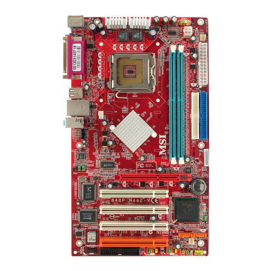
- Page 5 Introduction Thank you for choosing 848P-V2 Series (MS-7157 v1.x) ATX mainboard. The 848P-V2 Series is ® ® based on Intel 848P & Intel ICH5 chipsets for optimal system efficiency. Designed to fit the ® advanced Intel P4 Prescott processors in 478 pin package, the 848P-V2 Series delivers a high performance and professional desktop platform solution.
-
Page 6: Specifications
Pentium 4 Prescott processors in 478 pin package. FSB 400 / 533 / 800 MHz (FSB 400 for Northwood Celeron only). Supports up to 3.4GHz or higher speed. (For the latest information about CPU, please visit http://www.msi.com.tw/program/products/mainboard/mbd/pro_mbd_cpu_support.php) Chipset ® Intel 848P chipset Supports FSB 800/533/400MHz. - Page 7 ® Broadcom 4401 Integrated Fast Ethernet MAC and PHY in one chip. Supports 10Mb/s, 100Mb/s. Compliance with PCI 2.2. Supports ACPI Power Management. BIOS The mainboard BIOS provides “Plug & Play” BIOS which detects the peripheral devices and expansion cards of the board automatically. The mainboard provides a Desktop Management Interface (DMI) function which records your mainboard specifications.
-
Page 8: Memory Speed/Cpu Fsb Support Matrix
(For the latest information about CPU, please visit http://www.msi.com.tw/program/products/mainboard/mbd/pro_mbd_cpu_support.php.) MSI Reminds You... Overheating Overheating will seriously damage the CPU and the system, always make sure the cooling fan can work properly to protect the CPU from overheating. -
Page 9: Cpu Installation Procedures For Socket 478
To dissipate heat, you need to attach the CPU cooling fan and heatsink on top of the CPU. Follow the instructions below to install the Heatsink/Fan: Locate the CPU and its retention mechanism on the motherboard. Position the heatsink onto the retention mechanism. -
Page 10: Power Supply
2GB. To operate properly, at least one DIMM module must be installed. (For the updated supporting memory modules, please visit http://www.msi.com.tw/program/products/mainboard/mbd/pro_mbd_trp_list.php) Install at least one DIMM module on the slots. Memory modules can be installed on the slots in any order. -
Page 11: Chassis Intrusion Switch Connector: Jci1
Slave drive. You must configure second hard drive to Slave mode by setting the jumper accordingly. MSI Reminds You... If you install two hard disks on one cable, you must configure the second drive to Slave mode by setting its jumper. - Page 12 If the mainboard has a System Hardware Monitor chipset on-board, you must use a specially designed fan with speed sensor to take advantage of the CPU fan control. MSI Reminds You... Always consult the vendors for the proper CPU cooling fan.
-
Page 13: Pci Interrupt Request Routing
JBAT1 (Clear CMOS Jumper) to clear data. Follow the instructions in the image to clear the data. MSI Reminds You... You can clear CMOS by shorting 2-3 pin while the system is off. Then return to 1-2 pin position. Avoid clearing the CMOS while the system is on, which will damage the mainboard. -
Page 14: Bios Setup
BIOS Setup Power on the computer and the system will start POST (Power On Self Test) process. When the message below appears on the screen, press <DEL> key to enter Setup. DEL: Setup If the message disappears before you respond and you still wish to enter Setup, restart the system by turning it OFF and On or pressing the RESET button. -
Page 15: Frequency/Voltage Control
BIOS Setting Password Use this menu to set password. Save & Exit Setup Save changes to CMOS and exit setup. Exit Without Saving Abandon all changes and exit setup. Frequency/Voltage Control Current CPU Clock It shows the current clock of CPU. Read-only. CPU Clock Ratio This item allows you to adjust the CPU ratio. -
Page 16: Load Bios Defaults
Spread Spectrum When the motherboard’s clock generator pulses, the extreme values (spikes) of the pulses creates EMI (Electromagnetic Interference). The Spread Spectrum function reduces the EMI generated by modulating the pulses so that the spikes of the pulses are reduced to flatter curves. - Page 17 Introduction Félicitations, vous venez d’acquérir une carte mère ATX 848P-V2 Series (MS-7157 v1.x) La ® ® 848P-V2 Series est basée sur les Chipsets Intel 848P & Intel ICH5 offrant un système très ® performant. La carte fonctionne avec les processeurs Intel P4 Prescott 400/533/800MHz (Socket 478), est très performante et offre une solution adaptée tant aux professionnels qu’aux...
- Page 18 Supporte jusqu’à 2GB de mémoire non ECC. Supporte le seul canal DDR266/333/400 MHz. (Pour nue mise à jour sur les modules de mémoires supportés, veuillez visiter http://www.msi.com.tw/program/products/mainboard/mbd/pro_mbd_trp_list.php ) Slots Un slot AGP supportant 8x/4x à 1.5V (le 3.3V n’est pas supporté).
- Page 19 ® Broadcom 4401 Fast Ethernet MAC et PHY Integré dans une puce. Supporte 10Mb/s, 100Mb/s. Compatible avec PCI 2.2. Supporte l’ACPI Power Management. BIOS La carte procure un BIOS “Plug & Play” qui détecte automatiquement les cartes d’extension ou les périphériques. La carte offre une interface DMI (Desktop Management Interface) qui enregistre les spécificités de la carte mère.
-
Page 20: Panneau Arrière
+ ventilateur permettant la dissipation de la chaleur. Pour connaître le modèle de ventilateur nécessaire à la bonne utilisation de votre système n’hésitez pas à contacter votre revendeur. (Pour connaître les dernières informations concernant le CPU, veuillez visiter (http://www.msi.com.tw/program/products/mainboard/mbd/pro_mbd_cpu_support.php) Exemple de Dérivation du CPU Core Speed Horloge CPU Ration Core/Bus... - Page 21 Connecter le câble d’alimentation sur le connecteur de la carte mère prévu à cet effet (3 broches). MSI Vous Rappelle... Surchauffe La surchauffe endommagera le CPU ainsi que le système, c’est pourquoi il faut un ventilateur adéquat afin de protéger votre PC.
- Page 22 Maître et un Esclave. Vous devez configurer le second disque en mode Esclave et ce à l’aide du cavalier situé à l’arrière. MSI Vous Rappelle... Si vous voulez installer deux disques durs, vous devez configurer le second en Esclave en configurant le cavalier. Se référer à la documentation du disque dur pour les instructions.
- Page 23 MSI Vous Rappelle... Ne pas tordre le câble à 90° afin de ne pas l’endommager et éviter les pertes de données lors du transfert. Connecteur CD-In: AUDIO2000 Le connecteur est destiné au branchement audio du CD-ROM Connecteur Chassis Intrusion Switch: JCI1 Ce connecteur est connecté...
- Page 24 USB 1.1. Idéal pour connecter des périphériques gourmand en bande passante (appareil photo numérique, caméra numérique etc). MSI Vous Rappelle... A noter que les broches VCC et GND doivent être correctement connecter afin d’éviter tout endommagement. Connecteur Port de série: JCOM1 (Optionnel) La carte mère offre un connecteur COM1 9-pin male DIN (sur le panneau...
- Page 25 Slots PCI (Peripheral Component Interconnect) Les slots PCI vous permettent la connexion de cartes d’extension selon vos besoins. Pour installer ou retirer une carte PCI, il faut que le PC soit éteint. Si la carte PCI nécessite des réglages, veuillez vous reporter à la documentation fournie avec cette dernière.
-
Page 26: Setup Du Bios
Setup du BIOS Lorsque le PC démarre le processus de POST (Power On Self Test) se met en route. Quand le message ci-dessous apparaît, appuyer sur <DEL> pour accéder au Setup. DEL: Setup Si le message disparaît avant que n’ayez appuyé sur la touche, redémarrez le PC à l’aide du bouton RESET. - Page 27 Load Optimized Defaults Utiliser ce menu pour charger les paramètres par défaut du BIOS. BIOS Setting Password Utiliser ce menu pour entrer un mot de passe Save & Exit Setup Sauvegarder les changements du CMOS et sortir de l’utilitaire de Setup. Exit Without Saving Abandonner tous les changements et sortir de l’utilitaire de Setup Frequency/Voltage Control...
- Page 28 Auto Detect PCI Clk Cet élément est utilisé pour détecter automatiquement les slots PCI. En position [Enabled], le système ne veut plus alimenter les slots PCI libres pour réduire les émissions éléctromagnétiques (EMI). Paramètres: [Enabled], [Disabled]. Spread Spectrum Les cartes mères créent des EMI (Electromagnetic Interference). La fonction de Spread Spectrum réduit ces EMI.
- Page 29 Einleitung Danke, dass Sie das 848P-V2 Series (MS-7157 v1.x) ATX Mainboard gewählt haben. Das ® ® 848P-V2 Series basiert auf den Intel 848P und Intel ICH5 Chipsätzen und ermöglicht so ein ® ® optimales und effizientes System. Entworfen, um die fortschrittlichen Intel...
-
Page 30: Spezifikationen
Unterstützt den Speicherausbau auf bis zu 2GB ohne ECC. Unterstützt Single Channel DDR266/333/400 MHz. (Um den letzten Stand bezüglich der unterstützten Speichermodule zu erhalten, besuchen Sie bitte http://www.msi.com.tw/program/products/mainboard/mbd/pro_mbd_trp_list.php ) Slots Eine 1,5V AGP 8-fach/4-fach Schnittstelle (3,3V nicht unterstützt). Vier PCI V2.3 32-Bit PCI Bus Sockel (3,3V/5V PCI Bus unterstützt). - Page 31 ® Broadcom 4401 Integrierter Fast Ethernet MAC und PHY in einem Chip. Unterstützt Betrieb mit 10Mb/s oder 100Mb/s. Erfüllt die Anforderungen gemäß dem Standard PCI V2.2 Unterstützt ACPI Stromsparfunktionalität. BIOS Das Mainboard- BIOS verfügt über “Plug & Play”- Funktionalität, mit der angeschlossene Peripheriegeräte und Erweiterungskarten automatisch erkannt werden.
-
Page 32: Hinteres Anschlusspaneel
Prozessorlüfter, setzen Sie sich bitte mit Ihrem Händler in Verbindung, um einen solchen zu erwerben und danach zu installieren, bevor Sie Ihren Computer anschalten. (Um die neuesten Informationen zu unterstützten Prozessoren zu erhalten, besuchen Sie bitte http://www.msi.com.tw/program/products/mainboard/mbd/pro_mbd_cpu_support.php) Beispiel zur Ermittlung des Kerntaktes Wenn... -
Page 33: Installation Des Cpu Kühlers
CPU-Kühler mit Lüfter auf der CPU installieren. Befolgen Sie zur Installation des Kühlers die folgenden Anweisungen: Machen Sie die CPU und ihren Rückhaltemechanismus auf dem Motherboard ausfindig. Platzieren Sie den Kühlkörper auf dem Rückhaltemechanismus. Setzen Sie den Lüfter auf den Kühlkörper. Pressen Sie den Lüfter nach unten, bis seine vier Klammern in den Löchern des Rückhaltemechanismus einrasten. - Page 34 Volt beliebiger Reihenfolge eingesetzt werden. Gemäß Ihren Anforderungen können Sie sowohl ein- als auch doppelseitige Module verwenden DDR DIMMs haben nur eine Kerbe in der Mitte des Moduls. Sie passen nur in einer Richtung in den Sockel. Setzen Sie den DIMM- Speicherbaustein senkrecht in den DIMM- Sockel, dann drücken Sie ihn hinein, bis die goldenen Kontakte tief im Sockel sitzen.
- Page 35 Laufwerk muss durch das entsprechende Setzen einer Steckbrücke als Slave eingestellt werden. MSI weist darauf hin... Verbinden Sie zwei Laufwerke über ein Kabel, müssen Sie das zweite Laufwerk im Slave-Modus konfigurieren, indem Sie entsprechend den Jumper setzen. Entnehmen Sie bitte die Anweisun- gen zum Setzen des Jumpers der Dokumentation der Festplatte, die der Festplattenhersteller zur Verfügung stellt.
- Page 36 MSI weist darauf hin... Bitten Sie stets Ihren Händler bei der Auswahl des geeigneten CPU Kühlers um Hilfe. Frontpaneel Anschlüsse: JFP1/JFP2 Das Mainboard verfügt über zwei Anschlüsse für das Frontpaneel, diese dienen zum Anschluss der Schalter und LEDs des Frontpaneels. JFP1 erfüllt die Anforderungen des ®...
- Page 37 CMOS Jumper - Steckbrücke zur CMOS Löschung). Halten Sie sich an die folgenden Anweisungen, um die Daten löschen: MSI weist darauf hin... Sie können den CMOS löschen, indem Sie die Pins 2-3 verbinden, während das System ausgeschaltet ist. Kehren Sie danach zur Pinposition 1-2 zurück. Löschen Sie den CMOS nicht, solange das System angeschaltet ist, dies würde das Mainboard beschädigen.
-
Page 38: Bios Setup
BIOS Setup Nach dem Einschalten beginnt der Computer den POST (Power On Self Test - Selbstüberprüfung nach Anschalten). Sobald die Meldung unten erscheint, drücken Sie die Taste <Entf>(<Del>), um das Setup aufzurufen. DEL: Setup Wenn die Nachricht verschwindet, bevor Sie reagieren und Sie möchten immer noch ins Setup, starten Sie das System neu, indem Sie es erst AUS- und danach wieder ANSCHALTEN, oder die “RESET”-Taste am Gehäuse betätigen. - Page 39 H/W Monitor Dieser Eintrag gibt den „Gesundheitszustand“ Ihres PCs wieder. Frequency/Voltage Control Hier können Sie Einstellungen zu Taktfrequenz und Spannung vornehmen. Load Optimized Defaults In diesem Menü können Sie Werkseinstellungen für das BIOS laden, die der Hersteller für den Systembetrieb vorgibt. BIOS Setting Password Verwenden Sie dieses Menü, um das Kennwort einzugeben.
- Page 40 Auto Detect PCI Clk Hier wird automatisch festgestellt, welche PCI- Sockel belegt sind. Lautet die Einstellung auf [Enabled] (eingeschaltet), deaktiviert das System die Taktung leerer PCI- Sockel, um die Elektromagnetische Störstrahlung zu minimieren. Mögliche Einstellungen: [Enabled] (eingeschaltet ) und [Disabled] (ausgeschaltet). Spread Spectrum Pulsiert der Taktgenerator des Motherboards, erzeugen die Extremwerte (Spitzen) der Pulse Elektromagnetische Interferenzen (sog.
- Page 41 简介 ® 感谢您购买 848P-V2 Series(MS-7157 v1.x)ATX 主机板。848P-V2 Series 是采用 Intel 848P ® ® 和 Intel ICH5 芯片组,支持 Socket 478 的 Intel P4 Prescott 400/533/800MHz 处理器, 848P-V2 Series 提供了高性能、专业化的桌上型计算机解决方案。 布局...
- Page 42 规格 支持 Socket478 的 Intel 可支持时脉至 3.4GHz, FSB(外频)@800/533/400MHz。 (要瞭解关于 CPU 的最新信息,请参考 http://www.msi.com.tw/program/products/mainboard/mbd/pro_mbd_cpu_support.php ) 芯片组 ® Intel 848P 芯片组 支持 FSB 800/533/400MHz 支持 AGP 8X 界面 支持 DDR 400/333/266 内存界面 ® Intel ICH5 芯片组 高速 USB(USB2.0)控制器,最高速度为 480Mb/sec,8 个埠 2 个 Serial ATA/150 埠...
- Page 43 音效 AC97 连接控制器集成于 Intel 5.1-声道音效编解码 ADI AD1888 符合 AC97 v2.3 规格 符合 PC2001 音效需求 ® Broadcom 4401 集成 Fast Ethernet MAC 和 PHY 在同一芯片 支持 10Mb/s, 100Mb/s 符合 PCI 2.2 规格 支持 ACPI 电源管理 BIOS 主机板的 BIOS 提供“Plug & Play”(即插即用)功能,能够自动检测外围设备和连接于主 机板上的扩充卡...
- Page 44 后置面板提供以下界面: 硬件安装 本章将教您安装中央处理器、内存模块、扩充卡及设置主机板上的跨接器。附带并告诉您如何连接 鼠标键盘等周边装置。进行安装时请小心处理零组件并遵守安装步骤。 中央处理器 本主机板使用 Socket478 规格的 CPU 插槽,支持 Intel Pentium 4 /Celeron (D) 处理器。当您在 安装 CPU 时,请确认附有散热器与冷却风扇以防止 CPU 过热。如果没查找散热器与冷却风扇,请洽 询经销商购买,并在启动计算机之前,将散热器正确地安装在您的主机板上。 (有关更多的 CPU 消息,请至微星科技网站: http://www.msi.com.tw/program/products/mainboard/mbd/pro_mbd_cpu_support.php ) CPU 核心速度调整说明 如果 CPU 时脉 核心/汇流排比值 则 CPU 核心速度 内存速度/CPU FSB 支持对照表 Memory...
- Page 45 央处理器上方,确定您的中央处理器脚座的拉捍适当而且完全地进入脚座内。. 安装 CPU 风扇 下列指令将会引导您 CPU 散热风扇的安装,请询问相关技术人员协助安装。 1. 请您将 CPU 风扇放置在 CPU 风扇底座上。 2. 将风扇固定钩,钩住中央处理器滑动板的一端。 3. 同上,再将另一个风扇固定钩钩住。您可能需要用螺丝起子将风扇固定钩压下。 4. 将风扇电源线连接到主机板的风扇电源连接器。 MSI 提醒您… 温度过高 温度过高将会严重损坏您的 CPU 及系统,请确保您的散热风扇可以正常运作,以保护 CPU,避免发 生过热的情形。 更换 CPU 当您在更换 CPU 时,为了确保不会损坏 CPU,应该要先关掉 ATX 电源的开关,或将电源线拔掉。 内存 主机板提供 2 条插槽,可以插入 184-pin 无缓冲的 DDR 266 / DDR333 / DDR400 DDR SDRAM 内存,...
- Page 46 电源供应器 主机板使用 ATX 结构的电源供应器给主机板供电。在连接电源供应器之前,请务必确认所有的组件 都已正确安装,并且不会造成损坏。建议您使用功率为 300W 或以上的电源。 ATX 20-Pin 电源界面:ATX1 此连接器让您接上 ATX 电源。连接 ATX 电源时,请确认电源插头插入 的方向正确并对准脚位,然后将电源紧密地压入连接器内。 ATX 12V 电源界面:JPW1 此 12V 电源界面用于为 CPU 供电。 软盘驱动器界面:FDD1 主机板提供了 1 个标准的软盘驱动器界面 FDD1,支持 360K, 720K, 1.2M, 1.44M 和 2.88M 的软盘驱动器。 IDE 界面:IDE1/IDE2 主机板有2个32-bit增强PCI IDE和Ultra DMA 66/100控制器,支持PIO模式0~4, Bus Master和Ultra DMA 66/100工作模式,且它最多可连接4个设备,例如硬盘、CD-ROM、...
- Page 47 CD-In 界面:AUDIO2000 此界面为 CD-ROM 的音效界面。 机箱入侵检测接头:JCI1 此接头连接到 2 针脚的机箱开关界面。若机箱打开了,开关会被短接, 系统会自动记录状态。要清除警告,您必须进入 BIOS 设置,清除状态。 风扇电源界面:CPUFAN1/PWRFAN1/SYSFAN1 此 3-pin 的 CPUFAN1(处理器风扇)和 3-pin 的 PWRFAN1 (电源风扇) 、SYSFAN1 (系统风扇) 支持+12V 的系统散热风扇,可使用 3 –pin 或 4-pin 的接头。 当您将接线接到风扇接头时,请注意红色线为正 极 , 必须接到+12V, 而黑色线是接地, 必须接到 GND。 如果您的主机板有系统硬件监控芯片 , 您必须使用一个特别设计的支持速度检测的风扇方可使用此 功能。...
- Page 48 前置 USB 界面:JUSB1/JUSB2 主机板提供 2 个 USB2.0 的界面 JUSB1、JUSB2。USB 2.0 技术提 高资料传输速度,达到 480Mbps,是 USB1.1 的 40 倍。它可连接 高速资料传输速率的 USB 界面外围设备 ,如 USB HDD、 数码相机、 MP3 播放器、打印机、调制解调器等。 微星提醒您... 请注意,VCC 和 GND 的针脚必须安插正确,否则会引起主机板的损毁。 串列界面:JCOM1(选购) 主机板提供 1 个 9-pin 公头 DIN 界面作为串列界面 COM1(在后置面板上) , 和另...
- Page 49 PCI(外围设备连接)插槽 PCI 插槽可安装您所需要的扩充卡。当您在安装或拆卸 扩充卡的时候,请务必确认已将电源插头拔除。同时,请仔细阅读扩充卡的说明文档,安装和设置 此扩充卡必须的硬件和软件,比如跳线或 BIOS 设置。 PCI 中断请求队列 IRQ 是中断请求队列和中断请求确认的缩写,将设备的中断信号送到微处理器的硬件列表。PCI 的 IRQ 针脚一般都是连接到如下表所示的 PCI 汇流排的 INT A# ~ INTD# 引脚: Order1 PCI Slot 1 INT B# PCI Slot 2 INT C# PCI Slot 3 INT D# PCI Slot 4 INT A# Order2 Order3...
- Page 50 BIOS 设置 计算机加电后,系统将会开始 POST (开机自我测试)过程。当屏幕上出现以下信息时,按<DEL> 键即可进入设置程序。 DEL: Setup 如果信息在您做出反应前就消失了,而您仍需要进入 Setup,请关机后再开机或按机箱上的 Reset 键, 重启您的系统。您也可以同时按下<Ctrl>、<Alt>和<Delete>键来重启系统。 主页面 Standard CMOS Features(标准 CMOS 特性设置) 使用此功能表可对基本的系统配置进行设置。如时间,日期等。 Advanced BIOS Features(高阶 BIOS 特性设置) ® 使用此功能表可对 Award 系统的高阶特性进行设置。 Advanced Chipset Features(高阶芯片组特性设置) 使用此功能表可以更改芯片组寄存器的值,优化系统的性能表现。 Integrated Peripherals(集成周边设置) 使用此功能表可以对外围设备进行特别的设置。 Power Management Setup(电源管理特性设置) 使用此功能表可以对系统电源管理进行特别的设置。 PNP/PCI Configurations(PNP/PCI 配置)...
- Page 51 Frequency/Voltage Control(频率/电压控制) 使用此功能表指定您频率/电压控制的设置。 Load Optimized Defaults(装入 BIOS 设置值) 选择此项可装入工厂设置的 BIOS 系统设置设置值。 BIOS Setting Password(BIOS 设置口令) 使用此项功能表可设置口令。 Save & Exit Setup(保存后退出) 保存对 CMOS 的更改,然后退出 Setup 程序。 Exit Without Saving(不保存退出) 放弃对 CMOS 的更改,然后退出 Setup 程序。 频率/电压控制 Current CPU Clock(当前的外频时脉) 在此出现的是当前系统的时脉(只读)。 CPU Clock Ratio(CPU时脉倍频) 此项用于调整...
- Page 52 Spread Spectrum(频展) 当主机板上的时脉震荡发生器工作时,脉冲的尖峰会生成 EMI(电磁干扰)。频率范围设置功能可 以降低脉冲发生器所生成的电磁干扰,所以脉冲波的尖峰会衰减为较为平滑的曲线。如果您没有遇 到电磁干扰问题,将此项设置为[Disabled],这样可以最佳化系统的性能表现和稳定性。但是如果 您被电磁干扰问题困扰,请开启此项,这样可以减少电磁干扰。注意,如果您超频使用,必须将此 项关闭。因为即使是微小的峰值漂移(抖动)也会引入时脉速度的短暂突发,这样会导致超频的处 理器锁死。 CPU Clock(CPU时脉) 此项可让您选择 CPU 前端系统汇流排的频率(以 MHz 为单位) ,通过调整 FSB 到更高频率对处理器 进行超频。 装入 BIOS 设置值 您可装入主机板制造商提供的稳定系统的 BIOS 设置设置值。...
- Page 53 簡介 感謝您購買 848P-V2 Series(MS-7157 v1.x)ATX 主機板。848P-V2 Series 是採用 Intel ® 和 Intel ICH5 晶片組 , 支援 Socket 478 的 Intel Series 提供了高性能、專業化的桌上型電腦解決方案。 主機板配置圖 ® P4 Prescott 400/533/800MHz 處理器, 848P-V2 ® 848P...
- Page 54 規格 支援 Socket478 的 Intel 可支援時脈至 3.4GHz, FSB(外頻)@800/533/400MHz。 (要瞭解關於 CPU 的最新資訊,請參考 http://www.msi.com.tw/program/products/mainboard/mbd/pro_mbd_cpu_support.php ) 晶片組 ® 848P 晶片組 Intel 支援 FSB 800/533/400MHz 支援 AGP 8X 介面 支援 DDR 400/333/266 記憶體介面 ® ICH5 晶片組 Intel 高速 USB(USB2.0)控制器,最高速度為 480Mb/sec,8 個埠 2 個 Serial ATA/150 埠...
- Page 55 音效 AC97 連接控制器集成於 Intel 5.1-聲道音效編解碼 ADI AD1888 符合 AC97 v2.3 規格 符合 PC2001 音效需求 ® Broadcom 4401 集成 Fast Ethernet MAC 和 PHY 在同一晶片 支援 10Mb/s, 100Mb/s 符合 PCI 2.2 規格 支援 ACPI 電源管理 BIOS 主機板的 BIOS 提供“Plug & Play”(即插即用)功能,能夠自動偵測周邊設備和連接於 主機板上的擴充卡...
- Page 56 後置面板提供以下介面: 硬體安裝 本章將教您安裝中央處理器、記憶體模組、擴充卡及設定主機板上的跨接器。附帶並告訴您如何連 接滑鼠鍵盤等週邊裝置。進行安裝時請小心處理零組件並遵守安裝步驟。 中央處理器 本主機板使用 Socket478 規格的 CPU 插槽,支援 Intel Pentium 4 /Celeron (D) 處理器。當您在 安裝 CPU 時,請確認附有散熱器與冷卻風扇以防止 CPU 過熱。如果沒找到散熱器與冷卻風扇, 請洽詢經銷商購買,並在啟動電腦之前,將散熱器正確地安裝在您的主機板上。 (有關更多的 CPU 訊息,請至微星科技網站: http://www.msi.com.tw/program/products/mainboard/mbd/pro_mbd_cpu_support.php ) CPU 核心速度調整說明 如果 CPU 時脈 核心/匯流排比值 則 CPU 核心速度 記憶體速度/CPU FSB 支援對照表 Memory...
- Page 57 5. 壓下拉捍以完成安裝。當您壓下拉捍的時候,中央處理器還是有可能會移動,請緊緊地按住中 央處理器上方,確定您的中央處理器腳座的拉捍適當而且完全地進入腳座內。. 安裝 CPU 風扇 下列指令將會引導您 CPU 散熱風扇的安裝,請詢問相關技術人員協助安裝。 1. 請您將 CPU 風扇放置在 CPU 風扇底座上。 2. 將風扇固定鉤,鉤住中央處理器滑動板的一端。 3. 同上,再將另一個風扇固定鉤鉤住。您可能需要用螺絲起子將風扇固定鉤壓下。 4. 將風扇電源線連接到主機板的風扇電源連接器。 MSI 提醒您… 溫度過高 溫度過高將會嚴重損壞您的 CPU 及系統,請確保您的散熱風扇可以正常運作,以保護 CPU,避免 發生過熱的情形。 更換 CPU 當您在更換 CPU 時,為了確保不會損壞 CPU,應該要先關掉 ATX 電源的開關,或將電源線拔 掉。 記憶體 主機板提供 2 條插槽,可以插入 184-pin 無緩衝的 DDR 266 / DDR333 / DDR400 DDR SDRAM 記憶體,支援的記憶體最大容量為...
- Page 58 電源供應器 主機板使用 ATX 結構的電源供應器給主機板供電。在連接電源供應器之前,請務必確認所有的元 件都已正確安裝,並且不會造成損壞。建議您使用功率為 300W 或以上的電源。 ATX 20-Pin 電源介面:ATX1 此連接器讓您接上 ATX 電源。連接 ATX 電源時,請確認電源插頭插 入的方向正確並對準腳位,然後將電源緊密地壓入連接器內。 ATX 12V 電源介面:JPW1 此 12V 電源介面用於為 CPU 供電。 軟碟驅動器介面:FDD1 主機板提供了 1 個標準的軟碟驅動器介面 FDD1 , 支援 360K, 720K, 1.2M, 1.44M 和 2.88M 的軟碟驅動器。 IDE 介面:IDE1/IDE2 主機板有2個32-bit增強PCI IDE和Ultra DMA 66/100控制器,支援PIO模式0~4, Bus Master和Ultra DMA 66/100工作模式,且它最多可連接4個設備,例如硬碟、CD-ROM、...
- Page 59 機箱入侵偵測接頭:JCI1 此接頭連接到 2 針腳的機箱開關介面。若機箱打開了,開關會被短接, 系統會自動記錄狀態。要清除警告,您必須進入 BIOS 設定,清除狀態。 風扇電源介面:CPUFAN1/PWRFAN1/SYSFAN1 此 3-pin 的 CPUFAN1(處理器風扇)和 3-pin 的 PWRFAN1(電源風扇) 、SYSFAN1(系統風扇) 支援+12V 的系統散熱風扇,可使用 3 –pin 或 4-pin 的接頭。當您將接線接到風扇接頭時,請注意紅色 線為正極,必須接到+12V,而黑色線是接地,必須 接到 GND。如果您的主機板有系統硬體監控晶片,您必須使用一個特別設計的支援速度偵測的風 扇方可使用此功能。 微星提醒您... 請詢問廠商以使用適當的 CPU 降溫風扇。 前置面板介面:JFP1/JFP2 主機板提供了 2 組機箱面板和電源開關、指示燈的連接介面 JFP1 和 JFP2。JFP1 是符合 Intel 前置音效介面:JAUD1 您可以在前置面板介面...
- Page 60 前置 USB 介面:JUSB1/JUSB2 主機板提供 2 個 USB2.0 的介面 JUSB1、JUSB2。USB 2.0 技 術提高資料傳輸速度,達到 480Mbps,是 USB1.1 的 40 倍。 它可連接高速資料傳輸速率的 USB 介面周邊設備,如 USB HDD、數碼相機、MP3 播放器、印表機、數據機等。 微星提醒您... 請注意,VCC 和 GND 的針腳必須安插正確,否則會引起主機板的損毀。 串列介面:JCOM1(選購) 主機板提供 1 個 9-pin 公頭 DIN 介面作為串列介面 COM1 (在後置面板上) , 和另 1 個選購的串列介面 COM1。它們都是 16550A 高速通信埠,可收發 16 bytes FIFO,可用來 連接串列滑鼠或其他串列設備。...
- Page 61 PCI(周邊設備連接)插槽 PCI 插槽可安裝您所需要的擴充卡。當您在安裝或拆卸 擴充卡的時候,請務必確認已將電源插頭拔除。同時,請仔細閱讀擴充卡的說明文件,安裝和設定 此擴充卡必須的硬體和軟體,比如跳線或 BIOS 設定。 PCI 中斷請求佇列 IRQ 是中斷請求佇列和中斷請求確認的縮寫,將設備的中斷信號送到微處理器的硬體列表。PCI 的 IRQ 針腳一般都是連接到如下表所示的 PCI 匯流排的 INT A# ~ INTD# 引腳: Order1 PCI Slot 1 INT B# PCI Slot 2 INT C# PCI Slot 3 INT D# PCI Slot 4 INT A# Order2 Order3...
- Page 62 BIOS 設定 電腦加電後,系統將會開始 POST (開機自我測試)過程。當螢幕上出現以下資訊時,按<DEL> 鍵即可進入設定程式。 DEL: Setup 如果資訊在您做出反應前就消失了,而您仍需要進入 Setup,請關機後再開機或按機箱上的 Reset 鍵, 重啟您的系統。您也可以同時按下<Ctrl>、<Alt>和<Delete>鍵來重啟系統。 主頁面 Standard CMOS Features(標準 CMOS 特性設定) 使用此功能表可對基本的系統配置進行設定。如時間,日期等。 Advanced BIOS Features(高階 BIOS 特性設定) ® 使用此功能表可對 Award 系統的高階特性進行設定。 Advanced Chipset Features(高階晶片組特性設定) 使用此功能表可以修改晶片組寄存器的值,優化系統的性能表現。 Integrated Peripherals(整合周邊設定) 使用此功能表可以對周邊設備進行特別的設定。 Power Management Setup(電源管理特性設定) 使用此功能表可以對系統電源管理進行特別的設定。 PNP/PCI Configurations(PNP/PCI 組態)...
- Page 63 Frequency/Voltage Control(頻率/電壓控制) 使用此功能表指定您頻率/電壓控制的設定。 Load Optimized Defaults(載入 BIOS 設定值) 選擇此項可載入工廠設定的 BIOS 系統設定設定值。 BIOS Setting Password(BIOS 設定密碼) 使用此項功能表可設定密碼。 Save & Exit Setup(儲存後退出) 儲存對 CMOS 的修改,然後退出 Setup 程式。 Exit Without Saving(不儲存退出) 放棄對 CMOS 的修改,然後退出 Setup 程式。 頻率/電壓控制 Current CPU Clock(目前的外頻時脈) 在此出現的是目前系統的時脈(唯讀)。 CPU Clock Ratio(CPU時脈倍頻) 此項用於調整...
- Page 64 Auto Detect PCI Clk(自動偵測PCI 時脈) 此項用於自動偵測 PCI 插槽。當設定為[Enabled],系統將移除(關閉)閒置的 PCI 插槽時脈,以 最小化電池干擾(EMI) 。設定值有:[Enabled], [Disabled]。 Spread Spectrum(頻展) 當主機板上的時脈震盪發生器工作時,脈衝的尖峰會產生 EMI(電磁干擾)。頻率範圍設定功能 可以降低脈衝發生器所產生的電磁干擾,所以脈衝波的尖峰會衰減為較為平滑的曲線。如果您沒有 遇到電磁干擾問題,將此項設定為[Disabled],這樣可以最佳化系統的性能表現和穩定性。但是如 果您被電磁干擾問題困擾,請開啟此項,這樣可以減少電磁干擾。注意,如果您超頻使用,必須將 此項關閉。因為即使是微小的峰值漂移(抖動)也會引入時脈速度的短暫突發,這樣會導致超頻的 處理器鎖死。 CPU Clock(CPU時脈) 此項可讓您選擇 CPU 前端系統匯流排的頻率(以 MHz 為單位) ,通過調整 FSB 到更高頻率對處 理器進行超頻。 載入 BIOS 設定值 您可載入主機板製造商提供的穩定系統的 BIOS 設定設定值。...
- Page 65 マザーボードのレイアウト 848P-V2 Series (MS-7157 v1.x) ATX マザーボードをお買い上げいただき、まことにありがとう ® ® ございます。 848P-V2 シリーズは Intel ICH5 チップセットに基づいています。 848P & Intel Socket478 ピンパッケージの Intel ® P4 Prescott 400/533/800MHz プロセッサのデザインに準拠 している 848P-V2 はハイ・パフォーマンスおよびプロフェッショナル・デスクトップ・ソリュ ーションを提供します。 レイアウト...
- Page 66 マザーボードの仕様 Socket 478 / Intel Pentium 4 プロセッサ (Prescott コア) Pentium 4 3.4GHz まで (FSB 800/533/400MHz) 対応。 (最新の CPU 対応表は下記のホームページからご参考ください。 http://www.msi.com.tw/program/products/mainboard/mbd/pro_mbd_cpu_support.php ) Chipset チップセット ® 848P チップセット Intel FSB 800/533/400MHz をサポート AGP 8X をサポート DDR 400/333/266 メモリインターフェイスをサポート ® ICH5 チップセット...
- Page 67 Audio ® 848P チップセットに統合した AC97 リンク・コントローラ Intel ADI AD1888 ソフトウェアコーデック 5.1 チャンネルオーディオ AC97 v2.3 スペック準拠 PC2001 オーディオ対応 ® Broadcom 4401 Fast Ethernet MAC 及び PHY 統合 10Mb/s and 100Mb/s を自動認識 PCI 2.2 規格に準拠 ACPI 電源管理機能をサポート BIOS 本製品の BIOS は接続された周辺機器や装着された拡張カードを自動的に認識する Plug &...
- Page 68 バックパネル バックパネルには以下のコネクタが用意されています。 ハードウェアセットアップ ここでは CPU、メモリ、拡張カード、ジャンパ設定について解説します。機器の取り付けの際 には本書の説明や指示を守り、機器の扱いに十分気をつけて行ってください CPU について 本製品は Socket478 プラットフォームのマザーボードで、Intel Pentium 4 (Prescott コア)プロセ ッサをサポートしています。CPU を取り付ける際に必ず覚えておくことは、CPU をソケットに 装着する場合 CPU とソケットの向きを正しく合わせることと、 CPU 装着後にヒートシンクとク ーリングファンを取り付けるということです。 ヒートシンクの取り付けの際には、 ずれたり傾い たりしないように注意して固定してください。 CPU コアクロックの設定 CPU クロック コア/バス比 CPU コアスピード ●注意事項 「過熱」について CPU 取り付け時の不具合により、CPU が過剰な熱を持つと、CPU やマザーボードが回復不可 能なダメージを受ける場合があります。使用する冷却ファンが正常に動作することを、...
- Page 69 Memory Speed/CPU FSB 対応表 Memory 400 MHz 533 MHz 800 MHz Socket 478 CPU のインストール手順 CPU を装着する前に必ず電源スイッチをオフにし、電源コードを抜いてください。 レバーをソケットから横方向に引っ張ってください。 そのままレバーを持ち上げるように してソケットとの角度が 90 度になるまで開きます。 ソケットのピン 1 と CPU の金色の矢印マークもしくは端が欠けている場所を確認してく ださい。それらを合わせるようにして CPU をソケットに挿入してください。 CPU がしっかりと装着されているのなら、ピンが見えないようになります。CPU が正し く装着されない場合、マザーボードに厳重なダメージを与えることになります。 CPU を奥まで押して、ソケットにしっかりと嵌めてから、レバーを閉じてください。レ バーが完全に閉じる前に、CPU を押した手を離さないでください。 CPU クーラーセットのインストール手順 プロセッサ技術の進歩によりスピードと性能が上がるにつれて温度管理がますます重要になっ...
- Page 70 メモリ 本製品には、最大 1GB のメモリ容量の 184 ピンソケットが 2 個あります。DDR DIMM スロッ ト上、DDR266//DDR333/DDR400 SDRAM モジュールをインストールすることができます。適 切に作動する為に、 少なくとも 1 つの DIMM モジュールをインストールする必要があります。 (最 新のメモリモジュール対応表は下記のホームページからご参考ください。 http://www.msi.com.tw/program/products/mainboard/mbd/pro_mbd_trp_list.php ) Volt DDR DIMM スロットには絵に描いてあるような"VOLT"の切れ込みがあります。 このため、 DIMM メモリは 1 方向にしか挿入できません。 DIMM メモリモジュールを DIMM スロットに垂直に差込み、押し込みます。 DIMM スロットの両側にあるプラスチッククリップが自動的に固定されます。 電源 メインボードでは、給電システムとして ATX 電源がサポートされています。電源コネクタをイ...
- Page 71 66/100 コントローラを搭載しています。 最大 4 つのハードディスク、 CD-ROM、 120MB フロッピー(将来の BIOS で予約されています) 、その他のデバイスを接続することが できます。 1 台目の HDD は必ず IDE1(プライマリ)に接続します。 IDE1 はマスターとスレイブに接 続することができますが、2 台目の HDD を追加する場合は HDD の設定をジャンパで スレイブに切り替える必要があります。IDE2 でもマスターとスレイブに接続すること ができます。 MSI Reminds You... ハードディスクを 2 台使用する場合は、ジャンパを使用して 2 台目のハードディスクをスレ ーブに設定する必要があります。 ジャンパの設定手順等につきましてはハードディスク製造業者 から用意されましたマニュアルを参照ください。 ® ICH5 によるシリアル ATA コネクタ: SATA1/SATA2 Intel 本製品はサウスブリッジ...
- Page 72 MSI Reminds You... CPUFAN を使用するには BIOS で CPUFAN ピンの種類を設定してください。 フロント・パネル・コネクタ: JFP1/JFP2 本製品には、フロント・パネル・スイッチや LED を対象とした 電子的接続用に、ひとつのフロント・パネル・コネクタが用意さ ® れています。JFP1 は Intel Guide に準拠しています。 フロント・パネル・オーディオ・コネクタ: JAUD1 JAUD1 フロント・パネル・オーディオ・コネ クタを使用すると、フロント・パネル・オーデ ィオを接続することができます。このコネクタ ® は、Intel Front Panel I/O Connectivity Design Guide に準拠しています。 MSI Reminds You... フロント・パネル・オーディオ・ヘッダに接続しない場合、信号の出力が背面オーディオ・ポー...
- Page 73 クリア CMOS ジャンパ: JBAT1 本製品は電池によって、マザーボードの設定を CMOS RAM で保 存しています。JBAT1 の 1-2 ピンがショートしている時、CMOS データをキープしています。マザーボードの CMOS の内容をクリ アするためには電源が入っていないときに 2-3 ピンをショートさ せます。 MSI Reminds You... CMOS をクリアするには、システムがオフの間にピン 2-3 をショート(短絡)します。次いでピン 1-2 をショートに戻します。システム起動時の CMOS のクリアは絶対止めて下さい。マザーボ ードの破損や火災などに及ぶ危険があります。必ず電源コードを抜いて下さい。 AGP (Accelerated Graphics Port) スロット AGP スロットは AGP グラフィックカードだけを挿...
- Page 74 BIOS Setup コンピュータを起動するとシステムは POST(Power On Self Test)過程に入ります。下記のメッ セージが画面に表示されている間に<DEL>キーを押すと設定画面に入ることができます。 DEL: Setup <DEL>を押す前にこのメッセージが消えてしまった場合、電源をいったん切ってからふたたび 投入するか、 <RESET>を押すかして、 システムを再起動してください。 <Ctrl>、<Alt>、 <Delete> を同時に押しても再起動できます。 メインメニュー Standard CMOS Features システムの基本的な設定をします。例えば﹑時間、日付など。 Advanced BIOS Features システムの特別機能の設定を行います。 Advanced Chipset Features チップセットに関する設定をしてシステムの性能を最適化します。 Integrated Peripherals IDE、シリアル、パラレルなどの各 I/O ポートの設定をします。 Power Management Setup 電源管理に関する設定を行います。 PNP/PCI Configurations プラグアンドプレイや...
- Page 75 Exit Without Saving 変更した CMOS 設定値を保存せずにセットアップを終了します。 Frequency/Voltage Control Current CPU Clock 現在の CPU を表示します(読み取りのみ)。 CPU Clock Ratio CPU コア電圧(Vcore)を調整します。 DDR Power Voltage DDR DRAM の電圧を調整します。メモリーの電圧を変更すると、システムが不安定になること があります。そのためデフォルト設定値を変更して長期間使用することは避けてください。 AGP Power Voltage AGP スロットに供給する電圧を上げることができます。電圧を変えるとグラフィックカードに 回復不能なダメージを与えることがあります。設定値の変更は行わないでください。 Auto Detect PCI Clk ここではインストールされた PCI カードのクロック周波数を自動的に認識する機能を有効/無効 に設定することができます。選択肢は Enabled(有効)と Disabled(無効)です。 Spread Spectrum クロックジェネレータがパルスを発生すると、...
- Page 76 EMI に問題がある場合は、Enabled に設定して EMI を軽減してください。オーバークロックを 使用している場合は必ず Disabled にしてください。ちょっとしたッターであっても一時的にブ ーストを引き起こすことがあり、 それによってオーバークロックされたプロセッサがロックして しまうことがあるからです。 CPU Clock CPU ホストバス、AGP (3V66)、 PCI のクロック周波数を設定します。この項目を設定するこ とで、オーバークロックが可能になります。 Load BIOS Defaults Load BIOS Default を実行することにより、マザーボードの各種設定を工場出荷時の状態に戻すこ とができます。...
Need help?
Do you have a question about the 848P-V2 Series and is the answer not in the manual?
Questions and answers